7 About Design Studio Extension
This chapter explains how to extend certain aspects of the Oracle Communications Network Integrity Optical Circuit Assimilation cartridge. See Network Integrity Developer's Guide for more information about extending cartridges. See Network Integrity Concepts for guidelines and best practices for extending cartridges.The following examples are explained in this section:
Creating a Custom Circuit Matcher
You can extend the Optical Assimilation Circuit Matcher processor to use custom circuit matching logic, such as different matching criteria or different name sources.
See "Optical Assimilation Circuit Matcher" for more information about the default circuit matching logic.
To create a custom circuit matcher processor:
-
Open Oracle Communications Design Studio in the Design perspective.
-
Create a Network Integrity cartridge project.
-
Make the cartridge project dependent on the Optical Circuit Assimilation cartridge project.
-
Create an assimilation action.
-
Add the Assimilate Optical Circuits action as a processor in your assimilation action.
-
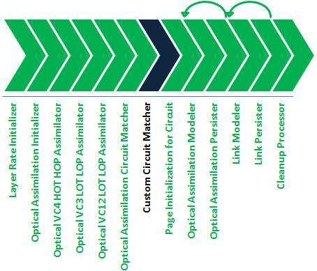
Create an assimilation processor named Custom Circuit Matcher to contain your custom circuit matching logic and insert it after the Optical Assimilation Circuit Matcher processor.
The Custom Circuit Matcher processor must fulfill all the functions of the Optical Assimilation Circuit Matcher processor. Your new action must also include a new condition on the Optical Assimilation Circuit Matcher processor that disables the Optical Assimilation Circuit Matcher processor, so only your new Circuit Matcher processor runs.
-
Build, deploy, and test your cartridge.
Your Custom Circuit Matcher processor is included and run by your new action, as shown in Figure 7-1.
Figure 7-1 Custom Circuit Matcher Processor Workflow

Description of ''Figure 7-1 Custom Circuit Matcher Processor Workflow''
SONET Assimilation
The Optical Circuit Assimilation cartridge can be extended to assimilate circuits in other types of optical networks. This example explains how to assimilate circuits in a SONET network and is based on JKLM values for SONET networks. See "About SONET JKLM Values" for more information.
To extend the cartridge to assimilate circuits in a SONET network:
-
Open Design Studio in the Design perspective.
-
Create a Network Integrity cartridge project.
-
Make the cartridge project dependent on the Optical Circuit Assimilation cartridge project.
-
Create an assimilation action.
-
Add the Assimilate Optical Circuits action as a processor in your assimilation action.
-
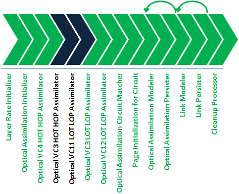
Create an assimilation processor for higher order circuits named Optical VC3 HOT HOP Assimilator and insert it after the Optical VC4 HOT HOP Assimilator processor.
This processor must fulfill all the functions of the Optical VC4 HOT HOP Assimilator processor.
-
Create an assimilation processor for lower order circuits named Optical VC11 LOT LOP Assimilator and insert it before the Optical VC12 LOT LOP Assimilator processor.
This processor must fulfill all the functions of the Optical VC12 LOT LOP Assimilator processor.
-
Build, deploy, and test your cartridge.
Your new assimilation processors are included and run by your new action, as shown in Figure 7-2.
Figure 7-2 SONET Assimilation Processor Workflow

Description of ''Figure 7-2 SONET Assimilation Processor Workflow''
About SONET JKLM Values
JKLM values are used to define the path and indexes a channel uses within the SONET hierarchy, where:
-
J is the AUG index (1..n)
-
K is the AU-3 index (1..3)
-
L is the TUG-2 index (1..7)
-
M is the TU-11 index (1..4)
The following list represents SONET JKLM channel index mappings:
-
J(AUG)=None
-
K(AU3)=VC3/ST1 44.736(DS3)
-
L(TUG-2)=None
-
M(TU-11)=VC11/VT15 1.544(DS1)
An example JKLM value for SONET connection termination point (CTP) VT-1.5 on an OC-12 is /sts1_au3-j=2-k=2/vt15_tu11-l=1-m=2.
Higher order transports (HOTs) and paths (HOPs) can ride on VC3(AUG/AU-3) pipes. Lower order paths (LOPs) can ride on VC11(AUG/AU-3/TUG-2/TU-11) pipes.
All pipes have either a J, JK, or JKLM value in the hierarchy. The Optical Circuit Assimilation cartridge models all pipes with full JKLM values, with a value of 0 for any unused indexes. A VC4 pipe with just a J value sets KLM indexes to 0 (for example: 3000). A VC3 pipe with just a JK value sets the LM indexes to 0 (for example: 3200).
Table 7-1 shows the layer rates for different types of cross-connects.
Network Boundary Partial Circuit Correction
The Optical Circuit Assimilation cartridge considers a partial circuit as one missing a drop port on either the start-port or the end-port. As such, this cartridge models circuits that leave the network boundary as partial, because port in the circuit that it can trace does not have a drop port.
You can extend the Optical Circuit Assimilation cartridge to model circuits that start or end outside the boundaries of the network or management scope as complete circuits, instead of as partial circuits.
To extend the cartridge to correct partial circuits that start or end at a network or management boundary:
-
Open Design Studio in the Design perspective.
-
Create a Network Integrity cartridge project.
-
Make the cartridge project dependent on the Optical Circuit Assimilation cartridge project.
-
Create an assimilation action.
-
Add the Assimilate Optical Circuits action as a processor in your assimilation action.
-
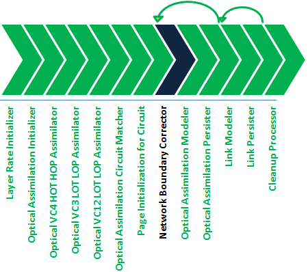
Create an assimilation processor named Network Boundary Corrector and insert it inside the ForEach processor that models the circuit data (after the Optical Assimilation Circuit Matcher processor).
-
Design the Correct Network Boundary processor to do the following:
-
Evaluate whether a partial circuit is truly partial or if the circuit path starts or ends outside the network or management boundary.
You must analyze your inventory or database information or another source of information that the processor uses to determine the boundary.
-
Set the circuit path for circuits starting or ending outside the boundary to the complete state.
The modeling processors interprets and models these circuits as complete circuits instead of as partial circuits.
-
-
Build, deploy, and test your cartridge.
Your new Correct Network Boundary processor is included and run by the Assimilate Optical Circuits action, as shown in Figure 7-3.
Figure 7-3 Network Boundary Partial Circuit Corrector Processor Workflow

Description of ''Figure 7-3 Network Boundary Partial Circuit Corrector Processor Workflow''