10 Quick Commissioning New Media Engine Systems
This chapter provides the basic information that allows you to configure Media Engine (ME) software after you have physically installed the system in your network. Commissioning enables an ME system or compatible third-party device to process WebRTC and WebRTC-Session Initiation Protocol (SIP) sessions.
Prerequisites to Quick Commissioning
Before using the information in this chapter, make sure that you have properly installed and cabled the system. The following ME documents provide additional information on configuring ME services, as well as how manage the system using the ME CLI and the ME Management System.
-
Oracle Communications WebRTC Session Controller System Administrator's Guide
-
Oracle Communications WebRTC Session Controller Media Engine Object Reference
Additionally, the Oracle Communications WebRTC Session Controller Release Notes provides important information about the software that you should review before commissioning a system in your network.
Steps 1 through 5 cover the tasks and services for getting the system up and running on an IP network so that the Ethernet interfaces can process WebRTC and WebRTC-SIP sessions. When enabled on an IP network, you can manage the system and its configuration remotely over the Internet using the ME Management System.
Steps 6 through 10 cover the tasks that allow you to control and monitor WebRTC and WebRTC-SIP sessions, as well as store call detail records and recordings.
Building the Configuration File
The ME configuration file (cxc.cfg) is made up of configuration objects and property settings that control how the system processes and manages WebRTC and WebRTC-SIP traffic. As you open these objects and set properties using the CLI or the ME Management System, the software builds a configuration hierarchy of objects that are applied to WebRTC and WebRTC-SIP sessions. You can display this configuration hierarchy using the show and show -v (verbose) commands.
For new users, as well as for users who are adding functionality to their configuration, you will need to open configuration objects using the config command to enable the default settings for those objects, even if you choose not to edit any of their associated properties. For example, if you need to enable the ICMP protocol and its default settings, you simply open the object and execute return, as shown in the session below. Notice that the ICMP object has been added to the configuration hierarchy at the end of the session on the eth4 interface.
config> config box interface eth4
config interface eth4> config ip 172.26.2.14
config ip 172.26.2.14> config icmp
config ip 172.26.2.14> return
config interface eth4> return
config box> return
config> show -v
interface eth4
  admin enabled
  mtu 1500
  arp enabled
  speed 1Gb
  duplex full
  autoneg enabled
  ip 172.26.2.14
   admin enabled
   ip-address dhcp
   geolocation 0
   metric 1
   classification-tag
   security-domain
   address-scope
   filter-intf disabled
   icmp
    admin enabled
    limit 10 5
To remove an object from the configuration hierarchy, use the CLI or ME Management System delete command. For more information on the delete command, see the Oracle Communications WebRTC Session Controller Media Engine Object Reference.
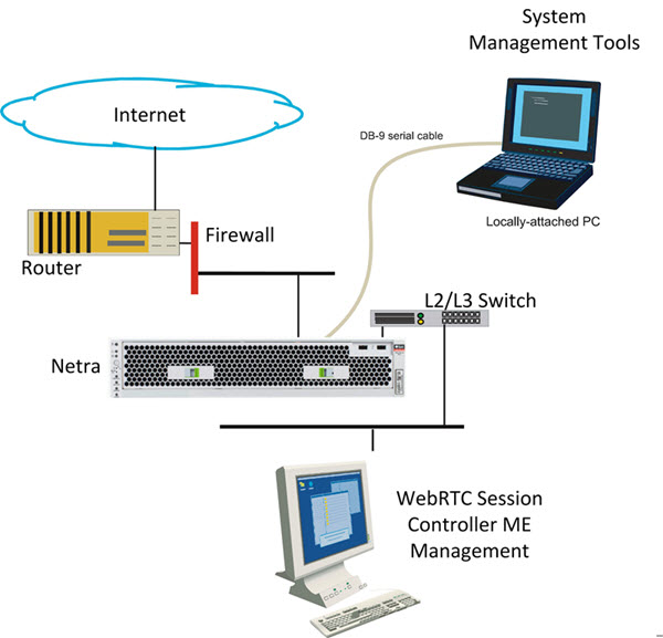
Basic Network Topology
Figure 10-1 illustrates a network topology using the ME with a directly-attached PC for initial setup, and the ME Management System for remote access using a graphical user interface.
Step 1. Configuring Basic IP Connectivity
Before you can manage an ME system remotely over the Internet using the ME Management System or over a Telnet or SSH connection, you need to locally assign an IP address to one of the Ethernet interfaces, eth0, eth1, eth2, or eth3. If you are setting up the device remotely, you will also need to configure an IP route, a route to a destination host or network, and a gateway IP address.
If you are using the ME Management System, you will also need to know the assigned IP address on one of the Ethernet ports to manage the ME configuration. The ME Management System application runs directly on the ME system over the Internet.
Example 10-1, "Configuring Basic IP Connectivity" shows a CLI session creates and enables an IP interface named 192.168.124.5, sets the static IP address and network mask, configures an IP route (if connecting remotely), and enables Web access on this IP interface. You will need to enable ICMP on the ME IP interface before you can use the ping command from your console to test the device as a responding node on the network. Use the show -v command to display the configuration.
CLI Session
Example 10-1 Configuring Basic IP Connectivity
NNOS-E> config box
config box> set hostname local2610
config box> config interface eth1
config interface eth1> config ip mgmt-int
Creating ’mgmt-int'
config mgmt-int> set admin enabled
config mgmt-int> set ip-address static 192.168.124.5/24
config mgmt-int> config routing
config routing> config route internetGateway
Creating ’route internetGateway'
config route internetGateway> set destination default
config route internetGateway> set gateway 192.168.124.3
config route internetGateway> return
config routing> return
config ip mgmt-int> config web
config web> set admin enabled
config web> set port 80
config web> return
config mgmt-int> config icmp
config icmp> set admin enabled
config icmp> top
config> save
config> show -v
Using the Setup Script
An optional configuration setup script called cxc.setup is now included with newly shipped systems. After installing a new system, you can run the script directly from the NNOS-E> prompt, as shown in Example 10-2.
Example 10-2 Using the Setup Script
CLI Session
NNOS-E> config setup
set box\hostname: <name>
config box\interface: eth1
set box\interface eth1\ip a\ip-address: <ipAddress/mask>
config box\interface eth1\ip a\ssh (y or n)? n
config box\interface eth1\ip a\web (y or n)? y
config box\interface eth1\ip a\routing\route: <routeName>
set box\interface eth1\ip a\routing\route localGateway\gateway:
<ipAddress>
set box\cli\prompt: <newPrompt>
Do you want to commit this setup script (y or n) y
Do you want to update the startup configuration (y or n)? y
The script presents a set of questions to help you with the initial system configuration. The information in the script includes the following:
-
Local hostname
-
IP interface names and addresses
-
SSH and Web access
-
Default route and any additional static routes per interface for remote management
-
User-defined CLI prompt
Every ME system has a minimum of two Ethernet interfaces. Any Ethernet interface on the system can be used for management traffic, however, Oracle recommends the use of eth1, as eth0 is reserved for fault-tolerant clustering with other ME systems. Management traffic is also supported on any interface that is carrying private or public network traffic. This means that it would be possible to use eth1 to carry WebRTC and WebRTC-SIP traffic and management traffic.
Note:
The /cxc directory on the ME system may include vendor-specific scripts that address unique startup configuration requirements. Specify the name of the script on the command line following the config setup command. For example: NNOS-E> config setup vendor.setup Check the /cxc directory for any vendor-specific setup files included with your system.Enabling Network Access
To ensure you can manage the system using services such as Telnet or the ME Management System, you must configure the ME system so that it is available on the network. You need to create a default (or static) IP route, a route to a destination host or network, and a gateway IP address.
After you configure the static route, enable ICMP and then use the ping command at the top-level of the CLI to test network accessibility.
For more information configuring static routes and enabling ICMP, see "Using the Setup Script".
Defining a Default Route and Gateway IP
If you are setting up the box remotely, you must configure an IP route, a route to a destination host or network, and a gateway IP address.
See "Step 1. Configuring Basic IP Connectivity" for the example CLI session that shows the routing context and the route named internetGateway. This is the default route that uses 192.168.124.3 as the default gateway.
Launching the Media Engine Management System
In addition to the CLI, you can use the ME Management System to configure the ME. To access the ME using the ME Management System, open an HTTP or secure HTTP window (HTTPS) to the IP address of the Eth0 port on the ME system. For example:
https://192.168.124.5
You should see the Oracle ME Log In window, illustrated in the following image.
By default, there are no user accounts configured on a new system. This means any value can be entered in for username & password, or leave the fields blank and click Login. Once you log in, the ME Management System main page appears. 
The remaining steps in this chapter use the ME Management System to commission the ME.
Changing the Linux Root Password
To change the Linux root password, use the secret root action. When prompted, specify and confirm the new password. For example:
NNOS-E>secret root
password:*******
confirm:*******
Success!
NNOS-E>
Note:
The password must be at least four characters long.For more information on the secret root action, see the Oracle Communications WebRTC Session Controller Media Engine Objects and Properties Reference Guide.
Step 2. Configuring Advanced IP Connectivity
Use the Configuration tab or the CLI to configure several additional Ethernet interfaces, as covered in "Step 1. Configuring Basic IP Connectivity". As a security device, the ME uses a default setting of disabled for these objects in the configuration file. This means that you must enable each interface. These objects include:
-
SSH: To enable SSH client connectivity on the interface
-
Media ports: To enable a range of port numbers for on the interface
-
SIP: To enable SIP traffic on the interface)
When editing Ethernet interface and examining each object using the ME Management System, note that many of the objects are already visible, but they are not yet enabled. For these objects to actually be enabled on the ME system, you must select the object and save the configuration.
After editing an interface configuration, elect Set, then Update & save configuration, as illustrated in the following image.
When you select Configuration/Update and save configuration you will be asked "Do you want to update the live configuration?" followed by "Do you also want to save the live configuration?" Click OK for both questions to ensure that the configuration is properly saved to the ME configuration file, cxc.cfg.
The following steps are necessary to set some specific parameters for the objects listed above:
-
Select the Configuration Cluster/ Box 1/Interface Eth0/IP local object on the left menu tree. Under the General field, edit the Media Ports properties as desired, then click Set.
-
Under the Other Properties field, edit the SSH properties. Accept the defaults by clicking Set.
-
Select SIP from the menu tree. Enter the following values for each fields:
-
admin: enabled (default)
-
NAT translation: disabled (default)
-
UDP port: Select Add UDP port, accept the defaults, then click Finish->Set.
-
TCP port: Select Add TCP port, accept the defaults, then click Finish->Set.
-
TLS port: Select Add TLS port, accept the defaults, then click Finish->Set.
-
Certificate: blank (default)
-
When you are finished editing the SIP fields, select Set->Configuration/Update and save configuration.
Step 3. Creating User Accounts for Basic Access
By default, the ME does not contain any predefined user accounts. This means it is possible to access the management interfaces without entering any login credentials (username and password). To properly secure ME/SE integration, however, you must configure two users. First configure a management user with access to all ME functionality. Then configure a web services user with access to web-services, actions, and statuses only.
Note:
You must configure the management user first. If you configure the web services user first, you will not be able to access the CLI or web UI.If you want to create a user account at this time, follow the steps below. If not, go directly to Step 4.
-
Using the ME Management System, select the Access tab, then select Access from the left menu pane. The Access Permissions/Configure Access page appears.
-
Under permissions, select Add permissions and create a permissions group called super-user and accept all default settings with all permission types enabled.
Select Set, then select Update and save configuration from the Configuration pull-down in the left pane.
-
From the Directories object, select Add users. Accept the default setting of enabled.
-
Select Add user and enter the required name and password of your choice, then re-enter the password to confirm your original password entry. In the permissions field, choose the permissions group that you just created (super-user).
-
Click Create. Select Configuration->Update and save configuration.
These steps created a username and password for a super-user account. Future attempts to log in to the ME (using the CLI or the ME Management System) will require that you specify these login credentials. If needed, you can also create user accounts with one or more of the super-user permissions.
Step 4. Enabling Master Services
The master-services configuration enables directory, accounting, database and registration services to run on the system. Perform the following steps to configure these master services:
-
Select the Services tab, then select master-services from the left menu pane.
-
Accept the default settings for cluster-master, directory, accounting, database (with Show advanced button selected), and registration. Click Set.
After you have configured all five services, select Configuration->Update and save configuration. The completed Master Services configuration appears.
Step 5. Configuring Basic Services
The Services configuration enables event logging and virus scanning services to run on the ME. Perform the following steps to configure event logging on the system.
-
Select the Services tab then select Services from the left menu pane.
-
On the Configure services page, select event-log from the menu pane, accept the defaults and click Set. Under the event-log configuration, additional options are available that you can configure.
You can direct the event logs to one or more of the following locations:
-
A syslog server
-
An ASCII file in an ME directory
-
A database on the ME system
-
An external database
-
-
In the file object, click Edit, then enter the name event-log in the text block. Click Set.
This configures event logging so that messages are written to the local file named event-log.
Step 6. Enabling the Virtual System Partition (VSP)
The ME virtual system partition (VSP) is the part of the system that holds the comprehensive customer-defined configuration that controls how the system processes, stores, directs, and routes WebRTC and WebRTC-SIP traffic. The VSP is where you can create session configurations, registration and dial plans, and policies that handle session message traffic that the system will receive and forward to a call destination, authentication and accounting database, service provider or enterprise server, and so on.
Using the ME Management System, perform the following steps.
-
Select the Configuration tab, then select vsp from the menu to open the Configure vsp page.
-
Under the general heading:, change the admin state to enabled.
-
Click Set, then select Configuration->Update and save configuration.
Step 7. Configuring the Accounting Environments
-
Select the ME Management System Configuration tab, then select vsp->accounting from the menu to display the Configure vsp\accounting page.
-
Under targets, click Configure next to the database field and set the admin property to enabled.
-
Click Add group and enter the target-name and mode property. Click Next. The Edit server screen appears.
-
Enter the database's name in the target-name field and select Create to display the Configure database group page.
-
Click Edit beside the server field and configure the following settings:
-
admin: enabled
-
name: localdb
-
type: Select local
-
username: postgres
-
password-tag: postgres
Note:
If you set the server type to local, using the local database as the accounting target, set the username and the password-tag to postgres. If you edit the username and password-tag properties to anything other than postgres, data will not be written to the database.
For information about password tags, refer to the Oracle Communications WebRTC Session Controller Media Engine Object Reference.
-
-
Click Set, then select Configuration->Update and save configuration.
Step 8. Configuring the Media Engine to Process SIP Traffic
The next step is to configure a default system policy that allows the ME to process SIP traffic. By default, and for security purposes, the ME does not allow any SIP traffic to pass.
-
Select the Configuration tab, then select vsp->default-session-config from the menu to display the vsp/default-session-config page.
-
In the sip-directive object, change the directive policy to allow, if not already set. This allows SIP traffic to traverse the ME system. Click Set.
-
Scroll down to the media object. Change the anchor property to enabled. Accept all other default settings.
-
Click Set, then select Configuration->Update and save configuration.
Step 9. Reviewing the Configuration
Once you have completed Steps 1 through 8, review the configuration to make sure it is accurate. A quick way to do this is to scan the ME Management System navigation tree to make sure there is an entry for each of the objects that you configured.
The following image is a listing of the Configuration and Services objects configured as part of basic ME commissioning. If you are using the CLI, run the show -v command from the ME prompt to display the configuration that you just created. The following image displays the configuration and services navigation trees.
Generating a Certificate
The ME communicates with the SE via HTTPS by default. While you can use a default self-signed certificate, you may need to generate one. This section describes generating a certificate.
Creating a Self-Signed Certificate and Key Pair from the Media Engine
Use the ME software to generate a cryptographic key pair and a self-signed X.509 certificate in PKCS#12 format. Once you create a self-signed certificate, you can generate the Certification Signing Request, a portion of which is required by the CA upon submission of their form.
Under the Actions tab, select cert-gen from the commands list. The Generate new key and certificates page appears.
Complete the fields on the Generate new key and certificates page.
-
keyFile: Specify the name and directory path of the resulting key name that you want to use, along with the p12 or .pfx file extension.
Example: /cxc/certs/<myNetworkKey>.p12
-
passphrase: Specify a password to be associated with the self-signed certificate. The text that you specify is encrypted in the certificate.
-
alias: Specify the FQDN of the ME system using this certificate, such as abc123.example.com. Omit HTTP:// and HTTPS://. This allows the certificate to be referenced.
Note:
The value (FQDN) you enter for the alias field must be identical to the value you enter for the common-name field. -
common-name: Specify the FQDN of the ME system using this certificate, such as abc123.example.com. Omit HTTP:// and HTTPS://. Do not use your personal name in this field. The common name is a component attribute of the certificate's distinguished name.
-
days-valid: Enter the number of days for which the certificate is valid. If your certificate if effective for one year, then enter the number 365.
-
country: Select the ISO country code: US (United States), AU (Australia), IN (India), IT (Italy), UK (United Kingdom), CA (Canada). The country is a component attribute of the certificate's distinguished name.
-
alternate-name: Typically a name that complies with the ASN.1 specification, such as a DNS name, IP address, or URI.
-
organization: Enter the name under which your business is legally registered. The listed organization must be the legal registrant of the domain name in the certificate request. If you are enrolling as a small business/sole proprietor, enter the certificate requestor's name in this field, and the DBA (doing business as) name in the organizational-unit field. The organization is a component attribute of the certificate's distinguished name.
-
organizational-unit: Use this field to differentiate between divisions within an organization. For example, ”Engineering” or ”Human Resources.” If applicable, you may enter the DBA (doing business as) name in this field. The organizational unit is a component attribute of the certificate's distinguished name.
-
state: If in the US, enter one of the fifty state names, in full, where your organization is located, such as Massachusetts; if outside the US, enter the full name of a province or region.
-
locality: Enter the name of a city.
When you are finished filling out the fields, click Invoke. A Success message appears.
Generating a Certification Signing Request
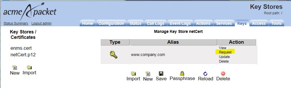
After you have created the self-signed certificate from the previous step, you must generate a certification signing request (CSR) that you can submit to the CA for the X.509 certificate. Select the request action.
The Generate Certificate Signing Request page and the resulting certificate signing request appear. Enter the password that you created in the previous step in the passphrase field and click Generate Certificate Signing Request. Select the key store file on the left and enter your password when prompted. Manage Key Store is displayed; click on Request under Action.
Click the Export to File button to save the CSR provided by the CA to external file.
If you choose to create a CSR in a PEM-formatted file, select the cert-request action.
Follow the instructions on the Certificate Signing Request page to copy and paste the text into the certificate application form provided by the CA.
Complete the fields on the Generate Certification Request page, using the same settings that you invoked from Step 1, as follows:
-
keyfile: Specify the name and ME directory path of the resulting key name that you want to use, along with the p12 or .pfx file extension. Example: /cxc/certs/<myNetworkKey>.p12
-
passphrase: Specify a password to be associated with the certificate issued by the CA. The text that you specify will be encrypted in the CSR.
-
alias: Enter an alias.
Note:
The value you enter for this field must be identical to the value you enter for the common-name field. -
csr-file: Specify the name and directory path of the resulting CSR file. This is the file from which you will cut and paste the required information for the CA at the time that you submit the certificate request. By default, the CSR file resides in the directory named /cxc/certs.
When you are finished filling out the fields, click Invoke. A Success message appears.
Signing a CSR Using Either a Valid CA or OpenSSL
After you generate the CSR, you must sign the CSR using one of two methods. You can either:
-
Sign the CSR using a well-known CA, (for example, VeriSign)
OR
-
Sign the CSR using Open SSL.
This section describes how to sign the CSR using either method.
Note:
If your network requires a ”trusted” certificate, then follow the instructions below to sign the CSR using a valid, well-known CA.Using a Certification Authority to Sign the CSR
You get the signed X.509 certificate from a valid CA, such as VeriSign. The CA issues a certificate stating and guaranteeing that the key contained in the certificate belongs to the person or organization noted in the certificate. The CA verifies the identify of the applicant's so that users can trust certificates issued by that CA to belong to the people and data identified in it, and not to an imposter.
Certificate Formats:
The ME certificate file can be in the following formats:
-
PKCS#12: Public Key Cryptography Standard #12 format from Microsoft IIS Version 5 (binary)
-
PEM: Privacy-enhanced mail (PEM) encoded format from any OpenSSL-based Web server (ASCII)
Using OpenSSL to Sign the CSR
This section provides information on how you can generate a self-signed certificate for testing TLS with the ME using OpenSSL. This is an alternative method to using a valid CA to sign the CSR.
This section describes how to do the following things:
-
Create an OpenSSL Certificate Authority (CA).
-
Generate a private key and CSR on the ME system and sign in with the OpenSSL CA.
-
Generate a Private Key and CSR without the ME system (not supported).
-
Use OpenSSL to convert an X.509 certificate and/or RSA key to a Public-Key Cryptography Standard #12 (PKCS#12) format.
Note:
Before using this method, download the OpenSSL program and install it on a Unix/Linux or Windows system. You also need to add the location of the OpenSSL executables to the PATH. In a Windows environment, this will need to do this manually, requiring a reboot to take effect.Creating an OpenSSL Certificate Authority
To create and Open SSL Certificate Authority (CA) on a Unix/Linux system, perform all steps as ”root.” On a Windows system, perform all steps as ”Administrator.”
-
Create directories to store certificates.
The main CA folder is the directory where the Certificate Authority files will reside. The ”private” directory stores the private keys. The ”certs” directory stores the certificates (or public keys). The ”csrs” directory stores the Certificate Signing Requests.
On Unix:
mkdir /CA
mkdir /CA/private
mkdir /CA/csrs
mkdir /CA/certs
Windows:
mkdir C:\CA
mkdir C:\CA\private
mkdir C:\CA\csrs
mkdir C:\CA\certs
-
Create files to support the generation process.
Create the ”index.txt” file with no contents. This is the database to which OpenSSL keeps track of generated certificates generated. Create the ”serial” file with a number so that each generated certificate is labeled with a number for tracking purposes.
Unix:
touch /CA/index.txt
echo 01 > /CA/serial
Windows:
copy con C:\CA\index.txt
echo 01 > C:\CA\serial
-
Create the OpenSSL configuration file.
Note:
The following are example values only.Unix:
Using a text editor, create "/CA/openssl.cnf."
[ ca ]
default_ca = local_ca
[ local_ca ]
dir = /CA
certificate = $dir/certs/ca.cer
database = $dir/index.txt
new_certs_dir = $dir/certs
private_key = $dir/private/ca.key
serial = $dir/serial
default_crl_days = 365
default_days = 365
default_md = md5
policy = local_ca_policy
x509_extensions = local_ca_extensions
[ local_ca_policy ]
commonName = supplied
stateOrProvinceName = optional
countryName = optional
emailAddress = optional
organizationName = optional
organizationalUnitName = optional
[ local_ca_extensions ]
basicConstraints = CA:true
nsCertType = server
[ root_ca_extensions ]
basicConstraints = CA:true
nsCertType = server
[ req ]
default_bits = 2048
default_keyfile = /CA/private/ca.key
default_md = md5
prompt = yes
distinguished_name = root_ca_distinguished_name
x509_extensions = root_ca_extensions
[ root_ca_distinguished_name ]
countryName = Country Name (2 letter code)
countryName_default = US
countryName_min = 2
countryName_max = 2
stateOrProvinceName = State or Province Name (full name)
stateOrProvinceName_default = MA
localityName = Locality Name (eg, city)
localityName_default = Maynard
0.organizationName = Organization Name (eg, company)
0.organizationName_default = Acme Packet, Inc.
organizationalUnitName = Organizational Unit Name
(eg,section)
organizationalUnitName_default = Support
commonName = Common Name (eg, YOUR name)
commonName_max = 64
emailAddress = Email Address
emailAddress_default = jgentile@acmepacket.com
emailAddress_max = 64
[ req_attributes ]
challengePassword = A challenge password
challengePassword_min = 4
challengePassword_max = 20
unstructuredName = An optional company name
Windows:
Using a text editor, create ”C:\CA\openssl.cnf.”
Note:
The following are example values only.[ ca ] default_ca = local_ca [ local_ca ] dir = C:\\CA certificate = $dir\\certs\\ca.cer database = $dir\\index.txt new_certs_dir = $dir\\certs private_key = $dir\\private\ca.key serial = $dir\\serial default_crl_days = 365 default_days = 365 default_md = md5 policy = local_ca_policy x509_extensions = local_ca_extensions [ local_ca_policy ] commonName = supplied stateOrProvinceName = optional countryName = optional emailAddress = optional organizationName = optional organizationalUnitName = optional [ local_ca_extensions ] basicConstraints = CA:false nsCertType = server [ root_ca_extensions ] basicConstraints = CA:true nsCertType = server [ req ] default_bits = 2048 default_keyfile = C:\\CA\\private\\ca.key default_md = md5 prompt = yes distinguished_name = root_ca_distinguished_name x509_extensions = root_ca_extensions [ root_ca_distinguished_name ] countryName = Country Name (2 letter code) countryName_default = US countryName_min = 2 countryName_max = 2 stateOrProvinceName = State or Province Name (full name) stateOrProvinceName_default = MA localityName = Locality Name (eg, city) localityName_default = Maynard 0.organizationName = Organization Name (eg, company) 0.organizationName_default = Acme Packet, Inc. organizationalUnitName = Organizational Unit Name (eg, section) organizationalUnitName_default = Support commonName = Common Name (eg, YOUR name) commonName_max = 64 emailAddress = Email Address emailAddress_default = jgentile@acmepacket.com emailAddress_max = 64 [ req_attributes ] challengePassword = A challenge password challengePassword_min = 4 challengePassword_max = 20 unstructuredName = An optional company name -
Generate the CA's private key and Master Certificate (public key).
This generates two files:
-
CA/private/ca.key (C:\CA\private\ca.key on Windows) – This is the CA's private key used to sign certificates. Keep this secure. If this key is compromised, it can be used to create certificates for malicious purposes.
-
CA/certs/ca.cer (C:\CA\certs\ca.cer on Windows) – This is the CA's certificate (public key). This is the file that would be distributed to client's ”Trusted Root” stores to trust any certificates signed by this CA's private key.
Unix:
openssl req -x509 -new -config /CA/openssl.cnf –days 3000 -out /CA/
certs/ca.cer
Windows:
openssl req -x509 -new -config C:\CA\openssl.cnf –days 3000 -out
C:\CA\certs\ca.cer
The ca.key is created automatically based on the configuration file.
Enter a strong passphrase for the CA key. Remember it, as this helps protect the security of your CA.
Fill in the following fields:
Country Name (2 letter code) [US]: <your country>
State or Province Name (full name) [MA]: <your state/province>
Locality Name (eg, city) [Maynard]: <your locale>
Organization Name (eg, company) [Acme Packet]: <your company>
Organizational Unit Name (eg, section) [Support]: <your department>
Common Name (eg, YOUR name) []: <Use the FQDN of the CA system
running OpenSSL>
Email Address []: <your email address>
Note:
The common-name field on the ”cert-gen” page is the most important. This is the name that is used to validate the certificate. Use the Fully Qualified Domain Name (FQDN) of the appropriate ME system, such as abc.123example.com.
-
-
Change permissions on the CA's key to only allow ”root” access:
Unix:
chmod 700 /CA/private/ca.key
Windows:
echo y|cacls C:\CA\private\ca.key /G %COMPUTERNAME%\Administrator:F
Note:
You only need to complete the process for setting up the CA once, while the processes for signing Certificates must be repeated every time a certificate needs to be generated.
Generating a Private Key and Certificate Signing Request Without the ME
Instead of generating the private key and CSR on the ME, you can generate it using OpenSSL exclusively. This is not the supported method.
-
Create a CSR and Private key for the ME system.
Unix:
openssl req -new -config /CA/openssl.cnf -out /CA/csrs/cxc_csr.pem
-keyout /CA/certs/cxc_pk.pem
Windows:
openssl req -new -config C:\CA\openssl.cnf -out
C:\CA\csrs\cxc_csr.pem -keyout C:\CA\certs\cxc_pk.pem
Use the OpenSSL ”req” utility to generate a Self-Signed Certificate (private key) and the Certificate Signing Request (CSR) in PEM format. In this example, the file names are cxc_pk.pem for the private key, and cxc_csr.pem for the CSR.
Enter a pass phrase for the CA key, and complete he following fields:
Country Name (2 letter code) [US]: <your country>
State or Province Name (full name) [MA]: <your state/province>
Locality Name (eg, city) [Maynard]: <your locale>
Organization Name (eg, company) [Acme Packet]: <your company>
Organizational Unit Name (eg, section) [Support]: <your department>
Common Name (eg, YOUR name) []: <Use the FQDN of the CXC>
Email Address []: <your email address>
Note:
The common-name field is the most important entry. This is the name that will be used to validate the certificate. Use the FQDN of the appropriate ME system, such as abc.123example.com.Currently, some phones, such as Eyebeam do not support wildcard certificates where common-name uses an asterisk character (*) in the domain name, such as *.example.com.
-
Sign the CSR with your OpenSSL CA.
Unix:
openssl ca -config /CA/openssl.cnf -in /CA/csrs/cxc_csr.pem –out /
CA/certs/cxc.pem
Windows:
openssl ca -config C:\CA\openssl.cnf -in C:\CA\csrs\cxc_csr.pem
–out C:\CA\certs\cxc.pem
Enter the pass phrase for the CA key, then respond y to the questions to generate and commit.
-
Merge the Private key and signed Public key into one file.
Unix:
cat /CA/certs/cxc.pem /CA/certs/cxc_pk.pem > /CA/certs/cxc.list.pem
Windows:
copy /CA/certs/cxc.pem + /CA/certs/cxc_pk.pem /CA/certs/
cxc.list.pem
-
Upload the newly generated cxc.list.pem file back to the ME, then configure a TLS certificate, as covered earlier in this chapter. Be sure to associate it with the SIP protocol on the appropriate network interface.
Note:
You can use the /CA/certs/ca.cer (C:\CA\certs\ca.cer on Windows) file to import into a ”Trusted Root Store.” For example, you can install this in Windows (Internet Explorer) for use with Soft Phones, such as Eyebeam. If you deploy the ca.cer file to multiple systems into the ”Trusted Root Store”, then those systems will ”trust” any certificates signed by this CA.
Using OpenSSL to Convert X.509 and RSA Keys
This section describes how to use OpenSSL to convert an X.509 certificate and/or RSA key to a Public-Key Cryptography Standard #12 (PKCS#12) format.
Requirements
You must have a working installation of the OpenSSL software and be able to execute OpenSSL from the command line.
Refer to ”CTX106627 - How to Install the OpenSSL Toolkit,” for more information on obtaining and installing OpenSSL.
The PKCS#12 specifies a portable format for storing and transporting certificates, private keys, and miscellaneous secrets. It is the preferred format for many certificate handling operations and is supported by most browsers and recent releases of the Windows family of operating systems. It has the advantage of being able to store the certificate and corresponding key, root certificate, and any other certificates in the chain in a single file.
To convert X.509 and RSA keys:
-
Ensure that the certificate(s) and key are in PEM format.
-
To convert a certificate from DER to PEM:
x509 –in input.crt –inform DER –out output.crt –outform PEM
-
To convert a key from DER to PEM:
rsa –in input.key –inform DER –out output.key –outform PEM
-
To convert a key from NET to PEM:
rsa –in input.key –inform NET –out output.key –outform PEM
Note:
The obsolete NET (Netscape server) format is encrypted using an unsalted RC4 symmetric cipher so a passphrase will be requested. If you do not have access to this passphrase it is unlikely you will be able to recover the key
-
-
Use the openssl command to read the PEM encoded certificate(s) and key and export to a single PKCS#12 file as follows:
openssl pkcs12 -export -in input.crt -inkey input.key -out
bundle.p12
Note:
By default, the key will be encrypted with Triple DES so you will be prompted for an export password (which may be blank).The PEM formatted root certificate and any other certificates in the chain can be merged into a single file such as root.crt, and included in the PKCS#12 file as follows:
openssl pkcs12 -export -in input.crt -inkey input.key -certfile
root.crt -out bundle.p12
Updating the Self-Signed Certificate
The cert-update action allows you to load the signed certificate that you receive from the CA. Once you have received the file, perform the following steps:
-
Upload the file to the ME using the Tools/Upload file function to browse for CA's certificate. Specify the destination path on the ME system, such as /cxc/certs, and specify the destination name of the certificate.
-
Select the Keys tab and select the appropriate key from the Key Stores list to display the Manage Key Store page.
-
Click Update to browse for the file that you uploaded.
-
Click Update to load the signed certificate to the CXC.
If you choose to update the certificate using the cert-update action rather than from the Keys tab, complete the fields as follows:
-
keyFile: Specify the name and directory path of the key that you want to update.
Example: /cxc/certs/<myNetworkKey>.p12
-
alias: Specify the alias for the keyFile name, if previously created.
-
password: Specify the password associated with the keyFile, as specified previously.
-
certFile: Specify the name and directory path of the signed certificate that you received from the CA and uploaded to the ME using the ME Management System Tools/Upload File function or other file transfer mechanism.
-
Subject Alternative Name for HTTPS Certificates Support
The ME supports Subject Alternative Name (SAN) for use with HTTPS certificates. SAN is a X509 version 3 certificate extension that allows one to specify a list of host names protected by a single SSL certificate.
To add multiple SANs to a certificate:
-
Select the Keys tab and either click New to create a new key store or select the existing store on which you want to add a certificate.
-
Enter a name and passphrase if creating a new key store and click Create. The key store appears.
-
Click New. The Generate New Self-Signed Certificate in Key Store X page appears.
-
Click Add beside the Alternate name field to add alternate host names be added to the certificate's subjectAltName field.
-
Click Create. The certificate appears in the key store.
Note:
When configuring the ME via the CLI, separate multiple SAN entries using the ’|' character.
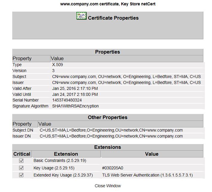
To view the SANs within a certificate click View next to the certificate name. The following image shows three SANs.
Configuring the Certificate on the Media Engine
Once you have imported the certificate to a directory on the ME system, configure the settings that control how the ME uses the certificate.
CLI Session
The following CLI session sets the directory and certificate destination file name path, specifies the passphrase.
NNOS-E>config vsp
config vsp>config tls
config tls>config certificate myNetworkCert.pfx
Creating ’certificate myNetworkCert.pfx'
config certificate myNetworkCert.pfx>set allow-null-cipher enabled
config certificate myNetworkCert.pfx>set passphrase-tag pass
By default, the ME only supports SSLv3 or TLSv1. If you require SSLv2 for interoperability, set this property true. Specify the passphrase-tag associated with the certificate file. Use this property if the certificate file is encrypted to have its private key information protected. This passphrase-tag must match the string with which the certificate was encrypted.
Deploying the Load Factor Application
The following sections describe the steps you must take to deploy the ME load factor application.
About the Load Factor Application
To balance request loads between SE nodes and ME nodes, you must deploy a custom load factor application on each ME node. The load factor application reports an appropriate cluster based load factor to a SE, and SE uses that load factor to choose which ME to relay requests to. SE favors less heavily loaded instances for new requests, balancing the load among multiple ME nodes.
About Load Factor Application Virtual Host Deployment Scenarios
There are two ways you can configure the load factor application virtual host:
-
Host name virtual hosting
-
IP virtual hosting
When configuring hostname virtual hosting, you assign an IP address to the load factor web service application, and you provide a Domain Name System (DNS) hostname for the virtual host.
When configuring IP virtual hosting, you assign an IP address to the load factor web service and another IP address to the virtual host.
Note:
Hostname virtual hosting is the recommended ME configuration scheme.Configuring Host Name Virtual Hosting
To configure hostname virtual hosting:
-
Navigate to the ME login page:
https://hostnameThe login page appears.
-
Enter your administration Username and Password, and click Login.
The ME home page appears.
-
Select the Configuration tab.
-
Expand the cluster node and select the interface node of the box you want to configure.
-
In the ip row of the configuration table, click Add ip.
-
Enter a name for the Web service interface, configure the ip-address information as required, and click Create.
-
Specify the HTTP transmission type, HTTP or HTTPS, as well as the Web service port number, and click Create.
-
In the virtual-host row of the configuration table, click Add virtual-host.
-
Enter the DNS hostname you have configured for the virtual host, make sure admin is set to enabled, and click Create.
Continue to "Configuring the Virtual Host web-app-config Object".
Configuring IP Name Virtual Hosting
To IP name virtual hosting:
-
Navigate to the ME login page:
https://hostnameThe login page appears.
-
Enter your administration Username and Password, and click Login.
The ME home page appears.
-
Select the Configuration tab.
-
Expand the cluster node and select the interface node of the box you want to configure.
-
In the ip row of the configuration table, click Add ip.
-
Enter a name for the Web service interface, configure the ip-address information as required, and click Create.
-
Select the interface node again.
-
In the ip row of the configuration table, click Add ip.
-
Enter a name for the Web service interface, configure the ip-address information as required, and click Create.
-
Select the ip object you created for the Web service, and in the web-service row of the Configuration table click Configure.
-
Specify the HTTP transmission type, HTTP or HTTPS, as well as the Web service port number, and click Create.
-
In the virtual-host row of the configuration table, click Add virtual-host.
-
Enter the IP address you have assigned to the virtual host, make sure admin is set to enabled, and click Create.
Continue to "Configuring the Virtual Host web-app-config Object".
Configuring the Virtual Host web-app-config Object
Once you have created and configured the ip objects, you must add a web-app-config object that points to the load factor Web Archive (WAR) file, to the virtual host.
To configure the virtual host's web-app-config object:
-
Log in to the ME console using a secure shell (SSH), and copy loadfactor.war from the /cxc/ws/samples directory to the /cxc_common/webapps directory.
-
Navigate to the ME login page:
https://hostnameThe login page appears.
-
Enter your administration Username and Password, and click Login.
The ME home page appears.
-
Select the Configuration tab.
-
Expand the cluster node and select the interface node of the box you want to configure.
-
Expand the ip object you created, expand web-service, and select the virtual-host object.
-
In the web-app-config row of the configuration table, click Add web-app-config.
-
Enter the path to the load factor application, /cxc_common/webapps/loadfactor.war and click Create.
-
In the context-parameter row of the configuration table, click Add context-parameter.
-
Enter meMgmtHost for the name, and the DNS name or IP address of the Web service for the value, and click Create.
-
In the context-parameter row of the configuration table, click Add context-parameter.
-
Enter meMgmtUsername for the name, and the hostname or IP address of the Web service for the value, and click Create.
Configuring Media Engine Communication with Signaling Engine
To enable communication between the ME and SE in your WebRTC Session Controller installation you must add the MEs to your SE configuration and configure the ME callback which specifies the load balancer endpoint for ME nodes.
Adding Media Engines to Signaling Engine
To add MEs to SE:
-
Start your SE servers if they are not already running. See "Starting the Signaling Engine Servers" for more information.
-
Navigate to the WebRTC Session Controller SE console and log in with your administrator username and password:
http://hostname:port/wsc-consoleNote:
The default SE console port is 7001. -
Select the Configuration tab.
-
Click Lock and Edit.
-
In the ME pane, enter the following information:
-
User: Enter the ME administrative username.
-
Password: Enter the password for the administrative username.
-
-
Click the Add button and enter the following information:
-
Address: Enter the hostname or IP address of the ME Node.
-
Port: Enter the port of the ME Node.
-
-
Click OK to save the ME Node. Add additional nodes as required.
-
Click Commit to save your changes.
For more information on the ME options, see Oracle Communications WebRTC Session Controller System Administrator's Guide.
Configuring the Media Engine Callback
To configure the ME callback:
-
Start your SE servers if they are not already running. See "Starting the Signaling Engine Servers" for more information.
-
Navigate to the WebLogic Server administration console and log in with your administrator user name and password:
http://hostname:port/consoleNote:
The default administration console port is 7001. -
In the Domain Structure pane, expand Environment, and select Servers.
-
In the Summary of Servers pane, select the Configuration tab.
-
Select your SE server from the Servers table.
Note:
You must repeat this procedure for each SE in a clustered environment. -
In the Settings for the SE, select the Protocols tab.
-
Select wsc-me-callback from the Network Channels table.
-
If you need to override the default values for Listen Address and Listen Port, uncheck Enabled.
-
Update the following information:
-
Listen Address and Listen Port: Enter the hostname or IP address and the port of the SE which will serve as the primary endpoint for the ME HTTP callbacks. You can only update this field if Enabled is unchecked.
-
External Listen Address and External Listen Port: Enter the hostname or IP address and port of the load balancer or the SE which will serve as the backup endpoint for the ME HTTP callbacks if the primary endpoint cannot be reached.
-
-
If you have modified the default values for Listen Address or Listen port, check Enabled.
-
Click Save.
-
Log out of the administration interface.
Configuring Media Engine Anchoring
Table 10-1 describes the media anchoring options supported by WebRTC Session Controller.
Table 10-1 WebRTC Session Controller Routing Options
| Scenario | Description |
|---|---|
|
Web to Web conditional anchoring |
Dynamic Media Anchoring (DMA) is enabled. Browsers are allowed to stream media between each other directly. If they cannot directly reach each other (for instance if they are behind a Network Address Translation (NAT) firewall and no Traversal Using Relays around NAT (TURN) service is configured), media is relayed through ME. Calls from WebRTC endpoints to and from non-WebRTC/SIP/PSTN endpoints are automatically supported. |
|
Web to Web forced anchoring |
DMA is enabled and all media is routed through ME. Calls from WebRTC endpoints to and from non-WebRTC/SIP/PSTN endpoints are automatically supported. |
|
Web to Web bypassing ME |
DMA is disabled, and nothing is passed through ME. This should only be done for diagnostic purposes. |
You can modify the anchoring behavior by modifying constants in the SE GroovyScript library.
To change the SE to ME anchoring scheme:
-
Start your SE servers if they are not already running. See "Starting the Signaling Engine Servers" for more information.
-
Navigate to the WebRTC Session Controller SE console and log in with your administrator user name and password:
http://hostname:port/wsc-consoleNote:
The default SE console port is 7001. -
Select the Script Library tab.
-
Click Lock and Edit.
-
Modify the script library as required:
-
For Web to Web conditional anchoring, set:
public static final DMA_ENABLED = true
public static final ME_CONFIG_NAME_DMA = web-to-web-anchor-conditional
-
For Web to Web forced anchoring, set:
public static final DMA_ENABLED = true
public static final ME_CONFIG_NAME_DMA = web-to-web-anchored
-
To bypass ME instances for diagnostic purposes:
public static final DMA_ENABLED = false
Note:
When DMA_ENABLED is set to false, the value of ME_CONFIG_NAME_DMA does not matter.
-
-
Click Validate Library to ensure you introduced no errors. Fix any errors that are reported.
-
Click Commit to save your changes.