6 VSM 6 Ethernet (IP) Data Path Connectivity
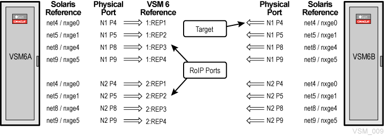
VSM 6 supports direct and multi-port director switch attachment between VSM 6 and VLE appliances, and CLINKs to other VSM 6 or VSM 5 VTSSs.
VLE traffic and CLINK traffic are not segregated by the VSM 6. Any RoIP port with connectivity will be used for either.
To define these connections, you need to define the RoIP ports that VSM 6 uses to replicate out and the ippaths to the targets.
VSM 6 Ethernet (IP) Port Assignments
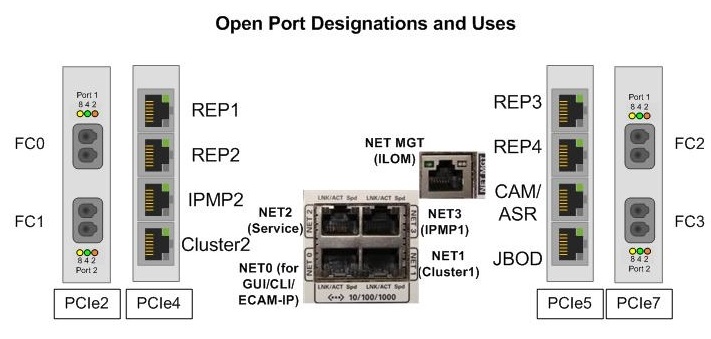
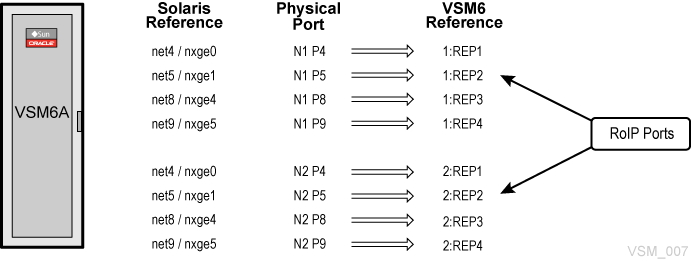
As shown in Figure 6-1, there are 12 Ethernet ports on each VSM 6 node. These port assignments assume Solaris 11.1 or higher is installed on the VSM 6 server nodes.
-
Port 0 (NET0) is for user interface connections (CLI, ECAM over IP).
-
Port 1 (NET1), port 3 (NET3), port 6 (IPM2), and port 7 (Cluster2) are connected between nodes for cluster support.
-
Port 2 (NET2) is a dedicated maintenance port reserved for direct connection by Services personnel.
-
Ports 4, 5, 8, and 9 (REP1, REP2, REP3,and REP4) are available for connection to the customer-defined network for IP replication use.
-
Port 10 (ASR) is available for Outbound ASR.
-
Port 11 (JBOD) connects the server(s) to the first disk shelf above them in the stack.
Network Port Scenarios
Common network port scenarios include:
-
Scenario 1: Connect the VSM 5 IFF port and a VSM 6 replication port in the data center.
Direct connections are made point-to-point with a network cable between interfaces, and the interface connections are on the same network. Only one connection is possible in this scenario. No gateway is required. Static routing is not required.
-
Scenario 2: Connect a VSM 5 IFF port and a VLE port to a VSM 6 replication port in the data center.
Connections are between interfaces through a switch, and the interface connections are on the same network. From one to many connections are possible. No gateway is required. Static routing is not required.
-
Scenario 3: Connect a VSM 6 replication port to a VSM 6 replication port in a remote data center, or set up ASR connection to a remote support site.
Connections between interfaces are through a gateway, and the interface connections are on different networks. From one to many connections are possible. A gateway is required. Static routing may be required if the customer cannot segregate and there is more than one route to the target.
A VSM 6 node is configurable in an environment such that one, two, or all three scenarios are implemented.
Node Configuration Example
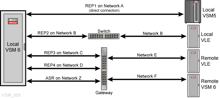
The example node configuration shown in Figure 6-2 covers all three scenarios:
-
The first replication port (network A) is connected directly to a local VSM 5 IFF port.
-
The second replication port (network B) is connected to a local VLE port through a switch.
-
The third replication port (network C) targets a remote VLE port on a different network.
-
The fourth replication port (network D) targets replication ports on a remote VSM 6 port on a different network.
-
ASR traffic (network Z) is sent to Oracle.
Direct, Switched, and Gateway Configuration Scenarios
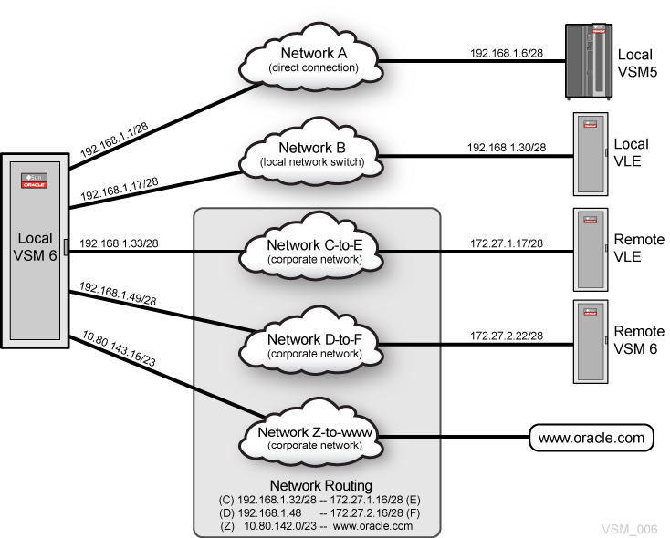
Figure 6-3 shows a network with a direct connection, a network with a switch connection, and three networks with connections through a gateway.
VSM 6 Ethernet (IP) Connectivity Considerations
As shown in Table 6-1, replication and ASR ports on a VSM 6 node that are configured on the customer network must be on unique separate networks.
Table 6-1 Ports Configured on Customer Network Need Separate Networks
| Location | Device | Link | Function | Customer Network | Separate Network |
|---|---|---|---|---|---|
|
PCIE4 |
nxge0 |
net4 |
Replication |
YES |
YES |
|
PCIE4 |
nxge1 |
net5 |
Replication |
YES |
YES |
|
PCIE5 |
nxge4 |
net8 |
Replication |
YES |
YES |
|
PCIE5 |
nxge5 |
net9 |
Replication |
YES |
YES |
|
PCIE5 |
nxge6 |
net10 |
Automated Service Requests |
YES |
YES |
Table 6-2 shows two networks, each with 254 IP addresses. If two or more ports have IP addresses within the range, then the ports are on the same subnet.
Table 6-2 Two Networks, Each with /24 Prefix Length (254 IP Addresses)
| Network | Netmask | Prefix Length | IP Address Range | Broadcast IP Address |
|---|---|---|---|---|
|
192.168.1.0 |
255.255.255.0 |
/24 |
192.168.1.1 - 192.168.1.254 |
192.168.1.255 |
|
192.168.2.0 |
255.255.255.0 |
/24 |
192.168.2.1 - 192.168.2.254 |
192.168.2.255 |
-
Ports with addresses of 192.168.1.10/24 and 192.168.1.25/24 are on the same network.
-
Ports with addresses of 192.168.1.10/24 and 192.168.2.25/24 are not on the same network.
Increasing the prefix length changes the netmask so that the 192.168.1.0 network is divisible into more networks or subnets. For example, as shown in Table 6-3, if the prefix length is changed to /28, the number of hosts per subnet is reduced from 254 down to 14.
Note:
You should plan ahead for future expansion needs during your initial configuration process. Reducing the prefix at a later time will affect adjacent networks and consequently will require network reconfiguration on all affected ports to ensure that IP addresses are valid and ports remain on separate networks.Table 6-3 Subnet Size Considerations
| Prefix | Netmask | Host IP Addresses per Subnet | Subnet Size Considerations |
|---|---|---|---|
|
/24 |
255.255.255.0 |
254 |
Up to 254 total replication, VLE, and VSM5 ports in the subnet |
|
/25 |
255.255.255.128 |
126 |
Up to 126 total replication, VLE, and VSM5 ports in the subnet |
|
/26 |
255.255.255.192 |
62 |
Up to 62 total replication, VLE, and VSM5 ports in the subnet |
|
/27 |
255.255.255.224 |
30 |
Up to 30 total replication, VLE, and VSM5 ports in the subnet |
|
/28 |
255.255.255.240 |
14 |
Up to 14 total replication, VLE, and VSM5 ports in the subnet |
|
/29 |
255.255.255.248 |
6 |
Up to six total replication, VLE, and VSM5 ports in the subnet |
|
/30 |
255.255.255.252 |
2 |
Maximum of one replication, VLE, or VSM5 port per VSM 6 node (two nodes total) in the subnet |
As shown in Table 6-4, when the network prefix length is changed to /28, ports with addresses of 192.168.1.10/24 and 192.168.1.25/24 are no longer on the same network.
Table 6-4 Two Networks with /28 Network Prefix (14 IP Addresses)
| Network | Netmask | Prefix Length | IP Address Range | Broadcast IP Address |
|---|---|---|---|---|
|
192.168.1.0 |
255.255.255.240 |
/28 |
192.168.1.1 - 192.168.1.14 |
192.168.1.15 |
|
192.168.1.16 |
255.255.255.240 |
/28 |
192.168.1.17 - 192.168.1.30 |
192.168.1.31 |
WARNING:
Infrastructure at the customer site must support any network configured on VSM 6 server nodes. Just configuring the ports and plugging them into a customer's network infrastructure is no guarantee that traffic will route properly.
Table 6-5 shows /28 networks to accommodate up to 14 network ports (a mix of VSM 6, VSM 5, and VLE ports) on a given network. The ASR port is on the customer's broader /23 network with a route to Oracle.
Note:
Both VSM 6 nodes are configured separately and independently. Replication and ASR ports for nodes may or may not be on the same subnets. For example, the REP1 port on Node1 and the REP1 port on Node 2 may or may not be on the same subnet.Table 6-5 /28 Networks and Ports Addresses
| Port | Network | Netmask | Length | IP Address Range | Broadcast Address |
|---|---|---|---|---|---|
|
REP1 |
192.168.1.0 |
255.255.255.240 |
/28 |
192.168.1.1 - 192.168.1.14 |
192.168.1.15 |
|
REP2 |
192.168.1.16 |
255.255.255.240 |
/28 |
192.168.1.17 - 192.168.1.30 |
192.168.1.31 |
|
REP3 |
192.168.1.32 |
255.255.255.240 |
/28 |
192.168.1.33 - 192.168.1.46 |
192.168.1.47 |
|
REP4 |
192.168.1.48 |
255.255.255.240 |
/28 |
192.168.1.49 - 192.168.1.62 |
192.168.1.63 |
|
ASR |
10.80.142.0 |
255.255.254.0 |
/23 |
10.80.142.1 - 10.80.143.254 |
10.80.143.255 |
Table 6-6 shows a sample layout between local VSM 6 ports and various target network ports using IP addresses provided by the customer.
Table 6-6 Sample Layout for VSM 6 Node 1 Ports and Target Network Ports
| Port (Node 1) | IP Address | Scenario | Gateway | Target Port | Target Address |
|---|---|---|---|---|---|
|
VSM6-REP1 |
192.168.1.1/28 |
1 (Net A) |
N/A |
Local-VSM5 |
192.168.1.6/28 |
|
VSM6-REP2 |
192.168.1.17/28 |
2 (Net B) |
N/A |
Local-VLE |
192.168.1.30/28 |
|
VSM6-REP3 |
192.168.1.33/28 |
3 (Net C) |
192.168.1.46 |
Remote-VLE |
172.27.1.17/28 |
|
VSM6-REP4 |
192.168.1.49/28 |
3 (Net D) |
192.168.1.62 |
Remote-VSM 6 |
172.27.2.22/28 |
|
VSM6-ASR |
10.80.143.16/23 |
3 (Net Z) |
10.80.143.254 |
Oracle-Support |
Oracle-Support |
Table 6-7 shows Node 2 with ports on the same subnets as those on Node 1.
Note:
If traffic to the remote-VLE and the remote-VSM can route from both VSM6-REP3 or VSM6-Rep4, then static routing may be necessary. Consequently, a gateway is required.Table 6-7 Sample Layout for VSM 6 Node 2 Ports and Target Network Ports
| Port (Node 2) | IP Address | Scenario | Gateway | Target Port | Target Address |
|---|---|---|---|---|---|
|
VSM6-REP1 |
192.168.1.2/28 |
1 (Net A) |
N/A |
Local-VSM5 |
192.168.1.7/28 |
|
VSM6-REP2 |
192.168.1.18/28 |
2 (Net B) |
N/A |
Local-VLE |
192.168.1.30/28 |
|
VSM6-REP3 |
192.168.1.34/28 |
3 (Net C) |
192.168.1.46 |
Remote-VLE |
172.27.1.17/28 |
|
VSM6-REP4 |
192.168.1.50/28 |
3 (Net D) |
192.168.1.62 |
Remote-VSM 6 |
172.27.2.22/28 |
|
VSM6-ASR |
10.80.143.17/23 |
3 (Net Z) |
10.80.143.254 |
Oracle-Support |
Oracle-Support |
VSM 6 IP Connectivity Examples
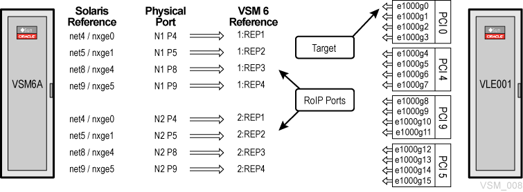
The following examples illustrate IP connectivity between VSM 6 and a VLE or VTSS:
Each example includes:
-
Connections between devices
-
CLI commands that define the connections to the VSM 6
-
VTCS commands that define the VSM 6 connections to the VTCS configuration
VSM 6 IP Replication: Define the Replication Ports
-
Each port defined as an RoIP is just a route out from the VSM 6.
-
The number of RoIP routes defined does not relate to the IPPATHs defined for the vRTD/CLINKs.
-
Multiple RoIP ports provide bandwidth and resilience.
VSM 6 VLE Connectivity: Define the IPPATH
-
VTCS uses the VLE name of the target defined on the IPPATH command used in the VSM 6 CLI. Each IPPATH is just a route out of the VSM 6 to the VSM target.
-
vRTDs are defined to VTCS as IP devices with IPIF ids.
-
The IPIF id is not used to reference the definition but must be present to meet VTCS syntax rules. Each IPIF id must be unique and with valid syntax for each VSM 6 defined in VTCS.
-
VTCS allows 16 IPIF ids total, so each VSM 6 can have a maximum combined total of 16 IP vRTDs/CLINKS in any combination.
VSM 6 CLINK Connectivity: Define the IPPATH
-
VTCS and VSM 6 use the VSM partner on the CLINK definitions and the VTSS target name on the IPPATH command to link the CLINKs. Each IPPATH is just a route out of the VSM 6 to the VSM target.
-
VTCS sees all VSM 6 CLINKs as IP devices.
-
CLINKs are defined to VTCS as IP devices with IPIF ids.
-
The IPIF id is not used to reference the definition but must be present to meet VTCS syntax rules. Each IPIF id must be unique for each VSM 6 defined in VTCS.
-
VTCS allows 16 IPIF ids total, so each VSM 6 can have a maximum combined total of 16 IP vRTDs/CLINKS in any combination.
-
VTCS can have multiple CLINKs defined even for a single IPPATH. Best practice is to define as many CLINKs to VTCS as possible.