7 VSM 6 FICON Data Path Connectivity
FICON ports connect the two VSM 6 nodes to the ELS host software and VTCS interface software on the MVS host systems, and to Real Tape Drives (RTDs) in the tapeplex. Attachment may be direct or through a switch.
There are four FICON ports per VSM 6 node, a total of eight for the VTSS. Each port supports IBM Control Unit (CU) and IBM Channel Mode (CH) images concurrently, so that when connected through a switch each port may attach to both hosts and RTDs. Sharing a HOST port with an RTD connection does not reduce logical pathing.
How it Works
-
The link between the VSM 6 and VTCS is the RTD NAME.
-
The link between VTCS and the RTD is the FICON cable to the relevant DEVNO in the relevant drive bay.
-
VSM 6 CLI commands define the connections to the VSM 6.
-
VTCS commands define the connections to the VTCS configuration.
-
VTCS uses the RTD name defined on the FICONPATH command used in the VSM 6 CLI.
-
Multiple FICONPATHs can route to the SAME RTD.
-
Physical RTDs are defined to VTCS as FICON devices with CHANIF ids.
-
The CHANIF id is not used to reference the device but must be present to meet VTCS syntax rules. Each CHANIF id must be unique and with valid syntax for each VSM 6 defined in VTCS.
-
VTCS allows 32 unique CHANIF ids. Each VSM 6 can have a maximum of 32 physical RTDs defined.
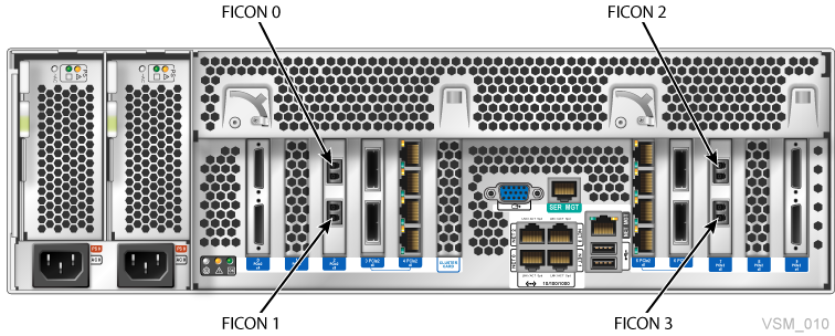
VSM 6 FICON Port Assignments
As shown in Figure 7-1, the FICON ports are numbered 0 to 3 beginning from the left top port when looking at the back of the server node.
VSM 6 RTD Connectivity Examples
The following examples illustrate FICON connectivity between VSM 6 and RTDs:
Each example includes:
-
Connections between devices
-
CLI commands that define the connections to the VSM 6
-
VTCS commands that define the VSM 6 connections to the VTCS configuration
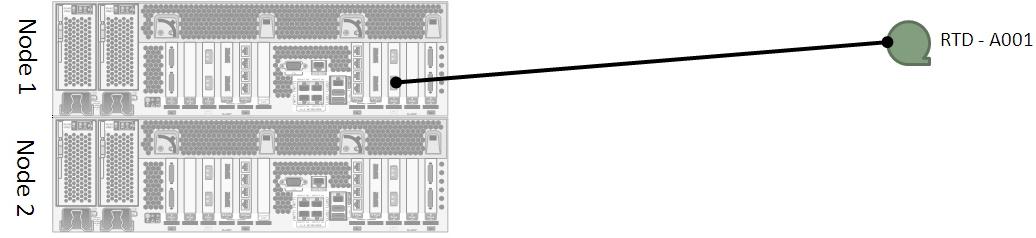
VSM 6 RTD Connectivity: Direct Connection
Figure 7-2 shows a direct connection between a VSM 6 FICON port and an RTD.
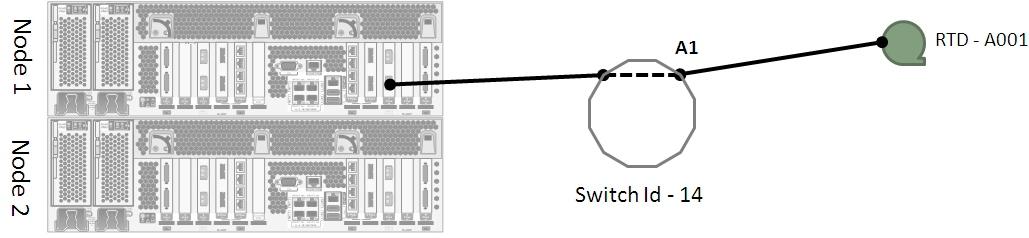
VSM 6 RTD Connectivity: Single Switch
Figure 7-3 shows a connection through a single switch between a VSM 6 FICON port and an RTD:
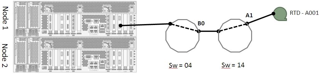
VSM 6 RTD Connectivity: Cascaded Switch
Figure 7-4 shows a connection through cascaded switches between a VSM 6 FICON port and an RTD.
VSM 6 RTD Connectivity: Dual RTDs
Figure 7-5 shows a connection through cascaded switches between a VSM 6 FICON port and two RTDs.
VSM 6 RTD Connectivity: Four RTDs One Port
Figure 7-6 shows a connection through cascaded switches between a VSM 6 FICON port and four RTDs. This is the maximum number of RTDs you can connect to a single VSM 6 FICON port, and there are eight ports total, so 32 RTDs maximum per VSM 6.
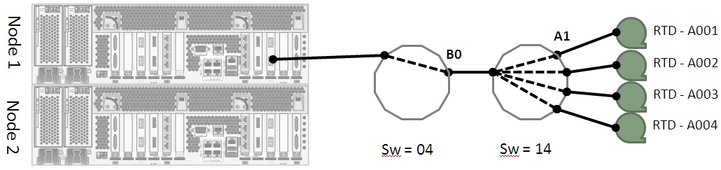
VSM 6 CLI Example:
vsmadmin: add ficonpath -name RTDA001 -node 1 –port 3 –domain 14 -area A1
vsmadmin: add ficonpath -name RTDA002 -node 1 –port 3 –domain 14 -area A2
vsmadmin: add ficonpath -name RTDA003 -node 1 –port 3 –domain 14 -area A3
vsmadmin: add ficonpath -name RTDA004 -node 1 –port 3 –domain 14 -area A4
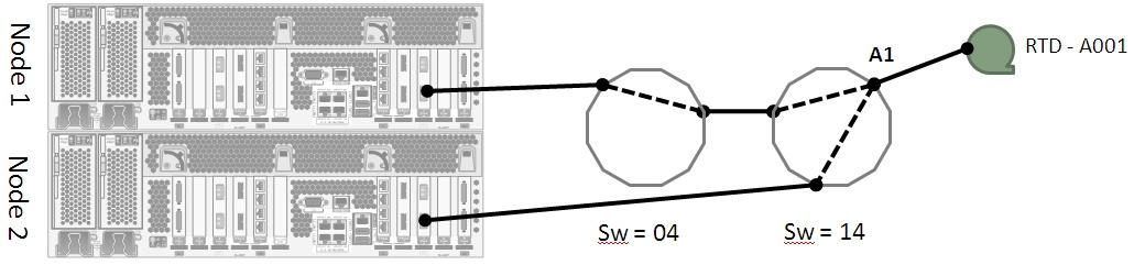
VSM 6 RTD Connectivity: Dual-Path RTD
Figure 7-7 and Figure 7-8 show two FICON paths to the same RTD. The connections are between two VSM 6 FICON ports located on separate VSM 6 nodes, through cascaded switches, to a single RTD. There is a single definition for the RTD in VTCS, and the VTSS resolves access down either path.
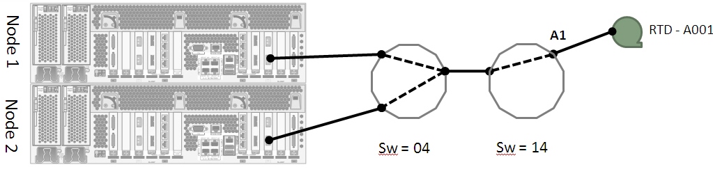
VSM 6 CLI Example 1:
vsmadmin: add ficonpath -name RTDA001 -node 1 –port 3 –domain 14 -area A1
vsmadmin: add ficonpath -name RTDA001 -node 2 –port 3 –domain 14 -area A1
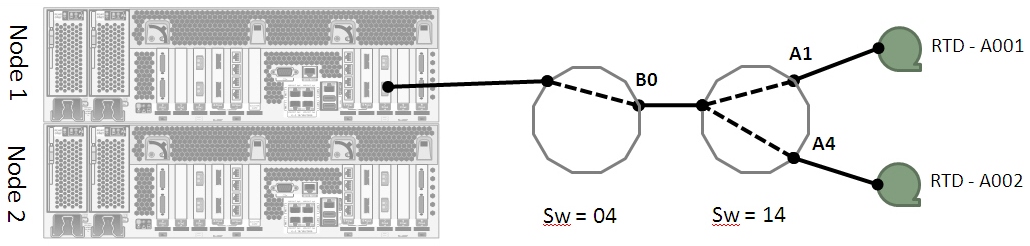
VSM 6 RTD Connectivity: Dual-Path Dual RTD
Figure 7-9 shows two FICON paths to two different RTDs. The connections are between two VSM 6 FICON ports located on separate VSM 6 nodes, through cascaded switches, to two RTDs.
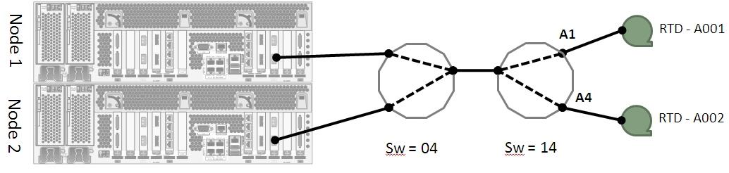
VSM 6 CLI Example:
vsmadmin: add ficonpath -name RTDA001 -node 1 –port 3 –domain 14 -area A1
vsmadmin: add ficonpath -name RTDA001 -node 2 –port 3 –domain 14 -area A1
vsmadmin: add ficonpath -name RTDA002 -node 1 –port 3 –domain 14 -area A4
vsmadmin: add ficonpath -name RTDA002 -node 2 –port 3 –domain 14 -area A4
VSM 6 RTD Connectivity: Multi-Path Dual RTD
Figure 7-10 shows multiple FICON paths to two different RTDs. The connections are between three VSM 6 FICON ports located on two separate VSM 6 nodes, through cascaded switches, to two separate RTDs. In this example, there are six FICON paths defined on the VSM 6 and two RTDs defined to VTCS.
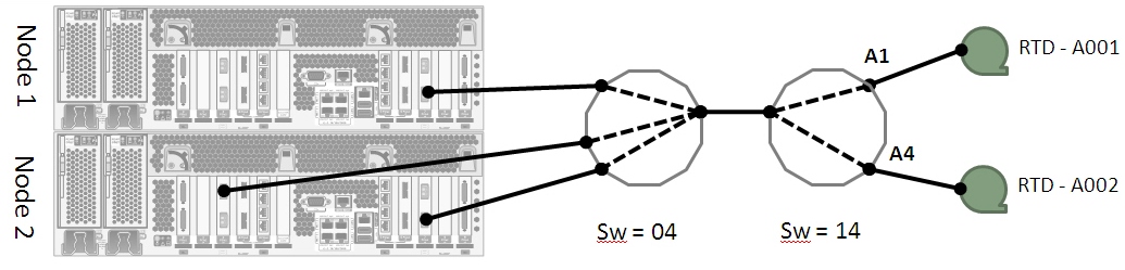
VSM 6 CLI Example:
vsmadmin: add ficonpath -name RTDA001 -node 1 –port 3 –domain 14 -area A1
vsmadmin: add ficonpath -name RTDA001 -node 2 –port 0 –domain 14 -area A1
vsmadmin: add ficonpath -name RTDA001 -node 2 –port 3 –domain 14 -area A1
vsmadmin: add ficonpath -name RTDA002 -node 1 –port 3 –domain 14 -area A4
vsmadmin: add ficonpath -name RTDA002 -node 2 –port 0 –domain 14 -area A4
vsmadmin: add ficonpath -name RTDA002 -node 2 –port 3 –domain 14 -area A4