2 Building an Event Connector
This chapter has the following sections:
2.1 Introduction to the Event Connector
Enterprise Manager Cloud Control 12c provides a Management Connector Framework (referred to as Connector Framework) to allow developers to build event connectors that can be used to create/update events in an external application.
For the connector to exchange data with the external application, a web service must be available that the connector can invoke to create and update event information. The connector is composed of a set of XML and XSLT metadata files that define how the connector appears in the UI and how it connects to and exchanges data with the external application.
To create an event connector for your own system, you need to provide a set of metadata files. Table 2-1 lists the categories of metadata files that comprise an event connector:
Table 2-1 Metadata File Categories
| Category | Type | Description |
|---|---|---|
|
Connector Descriptor |
XML |
The connector descriptor file defines the connector in Enterprise Manager. The file contains information about how the connector will appear in the UI, where the web service is located, how to connect to it, and what templates to use to translate data sent between systems. |
|
Request Templates |
XML or XSL |
These templates are used to generate XML requests that are sent to the web service to create or update an event. They translate the Enterprise Manager event data fields into the format expected by the web service. |
|
Response Templates |
XSL |
The response templates translate the XML response returned by a web service call into the format expected by the Connector Framework. |
2.2 How an Event Connector Functions
In order to know how to build an event connector, you need to understand how one functions. The connectorDeploy.xml file, commonly referred to as the connector descriptor file, defines the connector in Enterprise Manager. When the connector is installed, the contents of the connector descriptor file are examined by Enterprise Manager to determine what fields are required by the connector and what templates to use when exchanging XML messages with the web service.
When the operator configures the connector, the configuration page is generated based on the information in the connector descriptor file. Typically this includes fields that contain the URL and credentials to use when connecting to the web service. After the operator specifies the required fields, they click the Ok button to complete the configuration process. When the button is clicked, the configuration values are saved and any setup or initialization service operations defined by the connector are performed.
Note:
There are four optional service operations that can be specified. The setup and initialize operations are performed when the first instance of a connector is configured. These are used to perform any setup required to enable the connector. The other two operations are uninitialize and cleanup. These operations are used to undo anything that was done by the setup or initialize operations. Both of these operations are performed when the last instance of a connector is deleted.
If the configuration completed successfully, the connector is marked as completed and is ready to use. If an error occurs, the configuration changes will be saved but the connector will not be marked as completed. Someone must investigate why it failed and address the problem. Once the problem has been addressed, they can go back to the configuration page and click Ok to have perform setup/initialization again.
Once the connector is marked as completed, you can set up incident rules to create an event in the external application whenever certain events occur. For example you could set up a rule to create an event if any of your database tablespaces exceed a specified threshold. Whenever the rule is set up, you specify what target(s) the rule applies to, what criteria to use to trigger the rule, and the event connector to invoke.
Whenever the criteria are met and the rule fires, the Connector Framework invokes the event connector to generate the XML required to create an event in the remote application. The Connector Framework creates the request XML by performing an XSLT translation on the Enterprise Manager event data using the createEvent request template defined by the connector. The Connector Framework sends the generated create request to the web service URL configured for the createEvent service. The web service creates an event in the external application and sends a response with the identifier of the new event. The Connector Framework uses the createEvent response template to translate the new event identifier into the format expected by the Connector Framework. When the Connector Framework gets the response, it persists the external event identifier with the event.
Whenever something occurs that causes the event in Enterprise Manager to be updated, the Connector Framework uses the updateEvent request template to translate the Enterprise Manager event data format into an XML update request that it sends to the web service. The web service updates the event in the external application and sends a response. When the Connector Framework gets the response, it uses the updateEvent response template to translate the response into a format expected by the Connector Framework. This response is used by the Connector Framework to verify that the update was completed successfully.
When the event is eventually resolved and goes into a cleared status, the Connector Framework performs a normal updateEvent operation with the SeverityCode field set to CLEAR.
Note:
The current release only supports outbound operations (sending events to external applications). The support for inbound (importing) external events into Enterprise Manager may be considered for a future release.
2.3 Prerequisites
You must have a good understanding of the XML, XSD, and XSLT technologies because you will be required to generate several XML and XSLT files during the course of building a connector. It is highly recommended that you familiarize yourself with these technologies before attempting to build a connector.
2.4 Extracting Schema Files
To create the ticketing and event connectors, you will need access to the schema files that define the format of the different files. The schema files are located in the Extensibility Development Kit (EDK). To install the EDK, go to the Setup menu, select Extensibility, then Development Kit. This page gives instructions for downloading and installing the EDK. Review the Requirements section and verify the prerequisites have been met before attempting to install the EDK. Once the prerequisites are confirmed, install the EDK as directed in the Deployment section.
The schema files are located in the emMrsXsds.jar file in the emSDK directory. To access the files, you will need to extract them using the jar command or any other utility that understands the jar file format. Use the following command to extract the files using the jar command from the EDK installation directory:
$JAVA_HOME/bin/jar xvf emSDK/emMrsXsds.jar
Table 2-2 shows the location of the extracted schema files. This table will be referenced in the different sections where the schema files are discussed.
Table 2-2 Schema File Location
| File Name | Location |
|---|---|
connectorDeploy.xsd |
oracle/sysman/emSDK/core/connector/common |
EMEvent.xsd |
oracle/sysman/emSDK/core/connector/eventConnector |
EMEventResponse.xsd |
oracle/sysman/emSDK/core/connector/eventConnector |
SelfUpdateManifest.xsd |
oracle/sysman/emSDK/core/selfupdate/model |
setupResponse.xsd |
oracle/sysman/emSDK/core/connector/eventConnector |
initialze_response.xsd |
This file is not available in the EDK. See Example C-16 in Event Connector Samples. |
uninitialize_response.xsd |
This file is not available in the EDK. See Example C-17 in Event Connector Samples. |
2.5 Building an Event Connector
Now that you understand how a connector functions, you are now ready to start the process of building your event connector. To build your connector, you will need to follow the instructions specified in the sections listed below:
2.5.1 Determining Connector Functionality
Before you can build a connector, you need to analyze your requirements and determine what functionality to include in the connector. This section assists you in determining what templates you will require for your event connector. When you are done with this section, you should have a list of the templates that need to be implemented for your connector.
There are some templates that are required and must be included in every event connector. You have no choice but to include these templates. There are other templates that are optional that may be included in the connector if deemed necessary. Table 2-3 lists the possible templates that can be defined for an event connector. The Description column in this table explains the functionality provided by the template. You will need to analyze the functionality provided by the optional templates and determine which ones you need to include in your connector. Once you complete this analysis, you should have a list of templates that you need to provide. Your list will be comprised of the required templates plus the optional templates that you have selected for inclusion.
Note:
The optional templates are not used for most connectors. The only time you will want to use the optional template is when you need to make a web service call to set something up in the external application. An example of something that is done during initialization is the registration of the connector in the external application.
Table 2-3 Possible Event Templates
| Template | Required/Optional | Description |
|---|---|---|
|
setup request |
Optional |
Used to generate a request that is sent to the web service to perform setup for the connector. |
|
setup response |
Optional |
Used to translate the setup response from the web service to a format expected by Enterprise Manager. |
|
initialize request |
Optional |
Used to generate a request that is sent to the web service to perform initialization for the connector |
|
initialize response |
Optional |
Used to translate the initialization response from the web service to a format expected by Enterprise Manager |
|
createEvent request |
Required |
Used to generate a request that is sent to the web service to create an event. |
|
createEvent response |
Required |
Used to translate the create response from the web service to a format expected by Enterprise Manager |
|
updateEvent request |
Required |
Used to generate a request that is sent to the web service to update an event. |
|
updateEvent response |
Required |
Used to translate the update response from the web service to a format expected by Enterprise Manager |
|
uninitialize request |
Optional |
Used to generate a request that is sent to the web service to undo initialization for the connector. Required if the initialize template is defined. |
|
uninitialize response |
Optional |
Used to translate the uninitialize response from the web service to a format expected by Enterprise Manager. Required if the initialize template is defined. |
|
cleanup request |
Optional |
Used to generate a request that is sent to the web service to undo setup for the connector. Required if the setup template is defined. |
You will also need to determine the file name that you want to use for each template. There are no requirements on the template file names, but Oracle recommends that you use the following naming convention:
<methodName>_request.xml
<methodName>_request.xsl
<methodName>_response.xsl
Table 2-4 lists the recommended filenames for the different templates based on the suggested naming convention:
Table 2-4 Recommended Template Filenames
| Template | Recommended Filename |
|---|---|
|
setup request |
|
|
setup response |
|
|
initialize request |
|
|
initialize response |
|
|
createEvent request |
|
|
createEvent response |
|
|
updateEvent request |
|
|
updateEvent response |
|
|
uninitialize request |
|
|
uninitialize response |
|
|
cleanup request |
|
2.5.2 Developing Required Template Files
Now that you have identified the templates that you need to provide, the next step is to create the template files. It is highly recommended that you use XML/XSLT tools to generate and test the template files. You can create the files using a standard text editor but it will make the process much more difficult and time consuming. The tools catch format errors and allow you to test the templates before you package and install the connector in Enterprise Manager. This greatly reduces the number of corrections that you have to make to the installed connector. Each correction that you have to make to the connector requires that you uninstall the old connector, repackage and reinstall the new version of the connector.
The following subsections cover the steps required to create the different template files. You can ignore the sections that cover templates that are not targeted for your connector.
2.5.2.1 setup/initialize/uninitialize/cleanup Request Template
There is no event XML data to translate so these templates must be defined as XML files instead of XSLT files. Since these templates are defined as XML files, you just need to get a sample XML that is used to perform the operation that is required and use it as the XML file.
2.5.2.2 setup/initialize/uninitialize Response Template
The response template is an XSLT file that is used to transform the response from the web service into the format expected by Enterprise Manager. The format of the response XML from the web service should be defined by the WSDL or by a schema provided by the web service. The format expected by Enterprise Manager is specified in the initialize_response.xsd, setup_response.xsd, and uninitialize_response.xsd schema files. See Table 2-2 in the Extracting Schema Files section for the location of these schema files.
Example 2-1 shows a sample response file from the web service. Example 2-2 shows a sample XSLT template that is designed to transform the data to the format expected by Enterprise Manager. The XSLT template looks for a root element with a name of registerResponse that has the following namespace:
http://oracle.com/services/adapter-framework
It creates a SetupResponse root element with the following namespace:
http://xmlns.oracle.com/sysman/connector
It creates a child ConnectorVariable element that contains a VariableName element that it sets to REGISTRATION_ID. It also creates a VariableValue element and sets it to the identifier specified in the registrationId element. Example 2-3 shows the XML that was generated by performing the translation using an XSLT tool.
Example 2-1 Input Response XML from Web Service
<adap:registerResponse  xmlns:adap="http://oracle.com/services/adapter-framework">
   <adap:registrationId>2834782347</adap:registrationId>
</adap:registerResponse>
Example 2-2 Sample XSLT Template File
<?xml version='1.0' ?>
<xsl:stylesheet version="1.0" xmlns:xsl="http://www.w3.org/1999/XSL/Transform"
      xmlns:adap="http://oracle.com/services/adapter-framework">

  <xsl:template match="/adap:registerResponse">
    <SetupResponse xmlns="http://xmlns.oracle.com/sysman/connector">
      <ConnectorVariable>
        <VariableName>REGISTRATION_ID</VariableName>
        <VariableValue><xsl:value-of select="adap:registrationId"/></VariableValue>
      </ConnectorVariable>
    </SetupResponse>
  </xsl:template>

</xsl:stylesheet>
Example 2-3 File Resulting from Transformation
<?xml version="1.0" encoding="UTF-8"?>
<SetupResponse xmlns="http://xmlns.oracle.com/sysman/connector" xmlns:adap="http://oracle.com/services/adapter-framework">
   <ConnectorVariable>
      <VariableName>REGISTRATION_ID</VariableName>
      <VariableValue>2834782347</VariableValue>
   </ConnectorVariable>
</SetupResponse>
2.5.2.3 createEvent/updateEvent Request Template
These templates are the most difficult to build because they are larger and more complicated than the other templates. The input XML for the templates contain data about the Enterprise Manager event that was created/updated. The XML that results from the transformation is the XML that will be sent to the web service to create or update an event in the external application.
Before you can build your template, you need to understand the format of the data being created/updated in the external application and the format of the data coming from Enterprise Manager. Understanding the format involves identifying the fields that are available and the values that can be entered in those fields.
You need to familiarize yourself with the format of the data that is specified to create/update an event in the external application. A good place to start is the WSDL or a schema file that defines the format of the data. You will also need to see sample create/update requests to see how the data is formatted. If samples are not available, you should be able to manually retrieve data for an existing event using a XML client tool. This should give you a good idea of what the data looks like.
Once you understand the data in the external application, you then need to study and understand the data coming from Enterprise Manager. The fields that are available in the Enterprise Manager event data are identified in the EMEvent.xsd schema file. See Table 2-2 in the Extracting Schema Files section for the location of the EMEvent.xsd schema file.
The schema file identifies the fields and tells the type of data in those fields but doesn't give a good indication of what data is actually present. To get a good idea of what the data looks like you need a sample XML file that was generated by Enterprise Manager. Sample Event Data, shows sample event transactions that were generated by Enterprise Manager.
Once you are familiar with the data on both ends, you need to determine the mapping that will be performed by each template (createEvent and updateEvent). This involves determining what fields you will specify in the request and the format of the data for those fields. You only have two choices on the source of the data. You can hard code the data or get it from the Enterprise Manager event data. You can make the mapping as sophisticated or simple as you like. Ultimately, you will need to determine what fields and settings make sense for your environment.
Once you have identified mappings, you are now ready to build the XSLT files. To start the first template, copy the XML shown in Example 2-4 into your editor where you are building the XSLT file. This contains the basic skeleton that you will need to build your template. You will need to add your mapping logic in the designated location. The recommended approach is to build the createEvent template first and to test it thoroughly. Once you have verified that it works, you can make a copy of the template and use that as a baseline for the updateEvent template.
Create Event Template Example, walks through an example that shows how to build the createEvent template.
Example 2-4 Template Skeleton
<?xml version='1.0' encoding='UTF-8'?>
<xsl:stylesheet version="1.0"
              xmlns:xsl="http://www.w3.org/1999/XSL/Transform"
              xmlns:emcf="http://xmlns.oracle.com/sysman/connector">

  <xsl:template match="emcf:EMEvent">
      <!-- Add your mapping here -->
  </xsl:template>
</xsl:stylesheet>
2.5.2.4 createEvent/updateEvent Response Template
These templates are comprised of an XSLT file that is used to transform the response from the web service into the format expected by Enterprise Manager. The format of the response XML from the web service should be defined by the WSDL or by the schema used by the web service. The format expected by Enterprise Manager is specified in the EMEventResponse.xsd schema file. See Table 2-2 in the Extracting Schema Files section for the location of the EMEventResponse.xsd schema file.
Example 2-5 shows a sample response file from the web service. Example 2-6 shows a sample XSLT template that is designed to transform the data to the format expected by Enterprise Manager. The XSLT template looks for a root element with a name of createResponse that has a namespace of http://oracle.com/services/adapter-framework and a child element of return. It creates an EMEventResponse root element with a namespace of http://xmlns.oracle.com/sysman/connector and creates two child elements that are set depending on the contents of the identifier element in the input document. If the identifier element exists and contains data, it sets the SuccessFlag element to true and the ExternalEventId element to the identifier. If the identifier is not specified or is empty, it sets the SuccessFlag to false and creates an ErrorMessage element that is set to "Request to create an event in the external application failed". Example 2-7 shows the XML that was generated by performing the translation using an XSLT tool.
Example 2-5 Input Response XML from Web Service
<?xml version="1.0" encoding="UTF-8" ?>
<adap:createResponse xmlns:adap="http://oracle.com/services/adapter-framework">
   <return>
      <identifier>abcd-1234-5678</identifier>
      <status>0</status>
   </return>
</adap:createResponse>
Example 2-6 Sample XSLT Template File
<?xml version='1.0' ?>
<xsl:stylesheet version="2.0" xmlns:xsl="http://www.w3.org/1999/XSL/Transform"
    xmlns:oracleaf="http://oracle.com/services/adapter-framework"
    xmlns:a="http://xmlns.oracle.com/sysman/connector">

  <xsl:template match="oracleaf:createResponse/return">
    <a:EMEventResponse>
      <xsl:choose>
        <xsl:when test="identifier">
          <a:SuccessFlag>true</a:SuccessFlag>
          <a:ExternalEventId>
            <xsl:value-of select="identifier"/>
          </a:ExternalEventId>
        </xsl:when>
        <xsl:otherwise>
          <a:SuccessFlag>false</a:SuccessFlag>
          <a:ErrorMessage>Request to create an event in the external application failed</a:ErrorMessage>
        </xsl:otherwise>
      </xsl:choose>
    </a:EMEventResponse>
  </xsl:template>

</xsl:stylesheet>
Example 2-7 File Resulting from Transformation
<?xml version="1.0" encoding="UTF-8"?>
<a:EMEventResponse xmlns:a="http://xmlns.oracle.com/sysman/connector" xmlns:oracleaf="http://oracle.com/services/adapter-framework">
  <a:SuccessFlag>true</a:SuccessFlag>
  <a:ExternalEventId>abcd-1234-5678</a:ExternalEventId>
</a:EMEventResponse>
Whenever you create your XSLT template, it is easier to copy an existing template and customize it to fit your situation. To customize the template shown above:
-
Replace the
oracleafnamespace definition with the namespace that will be specified in the XML coming from your web service. -
Change the template match attribute to reference the root element in the XML coming from your web service.
-
Change the name of the element where it gets the event identifier information when it checks for an identifier and where it creates the
ExternalEventIdelement. -
Once you create your file, you should run an XSLT tool to test your template by transforming data from a sample XML and verify that it generates the correct XML format.
2.5.3 Defining the Connector Descriptor File
Now that you have the templates created, it is time to create a connector descriptor file that defines the connector in Enterprise Manager. The connector descriptor XML file describes the connector metadata and the configuration properties of the connector, such as web service end points and authentication schema.
The key points to remember when constructing a descriptor are:
-
The connector descriptor file name must be
connectorDeploy.xml -
The XML file should adhere to the
connectorDeploy.xsdschema.
See Table 2-2 in the Extracting Schema Files section for the location of the connectorDeploy.xsd schema file.
Refer to the sample connectorDeploy.xml in Event Connector Samples for reference implementation.
Table 2-5 lists the sections that comprise a connector descriptor and provides a summary of what each section does:
Table 2-5 Metadata Sections
| Metadata Section | Required | Explanation |
|---|---|---|
|
Connector Information |
Yes |
This section provides information about the connector that will be displayed at the UI. |
|
Authentication |
No |
Specifies the authentication method and the parameters that are required to connect to the web service. |
|
Service |
Yes |
This section is used to configure the URLs used to connect to the web service for the different service operations. |
|
Template Registration |
Yes |
This section is used to define all of the templates that are used for the connector. |
The following sections provide detailed information about the contents of the connector descriptor:
2.5.3.1 Connector Deploy Field Information
Each section of the connector deployment file contains fields that provide specific information about the connector. The following sections contain detailed information about what fields are available and what data goes in those fields.
2.5.3.2 Connector Information Section
The Connector Information section provides information about the connector such as name, version, description, etc., that will be displayed at the UI. Table 2-6 lists the fields in this section and provides an explanation of each field.
Table 2-6 Connector Information Fields
| Section/Field | Required | Description | |
|---|---|---|---|
|
Name |
Yes |
The connector name that will be displayed at the UI. |
|
|
Version |
Yes |
The connector version that will be displayed at the UI. |
|
|
EMCompatibleVersion |
Yes |
The earliest version of Enterprise Manager that is supported |
|
|
Description |
Yes |
The connector description that will be displayed at the UI |
|
|
Category |
Yes |
Possible values are:
    EventConnector
    TicketingConnector
In this case, the value will be |
|
|
NewTargetType |
Yes |
This section is not used but must be defined. |
|
|
|
Yes |
Name of the target type. |
|
|
|
Yes |
Name to display at the UI for the target type. |
|
|
|
Yes |
The name of the default target of the target type. |
|
|
|
Yes |
The name to display at the UI for the default target of the target type. |
|
2.5.3.3 Sample Connector Information Section
Example 2-8 shows the information that is included in the Connector Information section. All of the fields in this section are contained in the ManagementConnector node.
Example 2-8 Connector Information Section Sample
  <Name>SCOM 2012 Connector</Name>
  <Version>12.1.0.1.0</Version>
  <EMCompatibleVersion>12.1.0.1.0</EMCompatibleVersion>
  <Description>Microsoft System Center Operations Manager 2012 Integration with Enterprise Manager</Description>
  <Category>EventConnector</Category>
  <NewTargetType>
    <TargetTypeName>scom_managed_host</TargetTypeName>
    <TargetTypeDisplayName>SCOM Managed Host</TargetTypeDisplayName>
    <DefaultTargetName>generic_scom_managed_host</DefaultTargetName>
    <DefaultTargetDisplayName>Generic SCOM Managed Host</DefaultTargetDisplayName>
  </NewTargetType>
2.5.3.4 Authentication Section
The authentication section specifies the authentication method and the credentials that are required to connect to the web service. There are three possible authentication types that can be configured. If no authentication section is specified, no authentication will be performed when the connector connects to the web service. Table 2-7 lists the three possible authentication sections and the fields contained in each.
Table 2-7 Authentication Fields
| Section/Field | Required | Description | |
|---|---|---|---|
|
SOAPHeaderAuthentication |
No |
Specifies the credentials used to connect to the web service using SOAP header authentication. |
|
|
*Username |
Yes |
The username to specify in the SOAP header |
|
|
*Password |
Yes |
The password to specify in the SOAP header |
|
|
*AuthVariable |
No |
Up to 20 other variables to pass in the SOAP header |
|
|
*SOAPHeader |
Yes |
A string that serves as template for the SOAP header. It will be updated by substituting the user inputs for variables defined above in the designated location and bound with a HTTP request. |
|
|
HTTPBasicAuthentication |
No |
Specifies the credentials used to connect to the web service using basic authentication |
|
|
*Username |
Yes |
The username to specify when calling the web service |
|
|
*Password |
Yes |
The password to specify when calling the web service |
|
|
UserNameTokenAuthentication |
No |
Specifies the credentials used to connect to the web service using Username Token Profile authentication |
|
|
*Username |
Yes |
The username to specify |
|
|
*Password |
Yes |
The password to specify |
|
* Fields marked with an asterisk are comprised of the following subfields:
-
VariableName: Name of the variable being defined
-
DisplayName: Name to use when displaying information about this field at the UI
-
"required" attribute: Specifies whether the field is required (defaults to false if not specified)
2.5.3.5 Sample Authentication Section
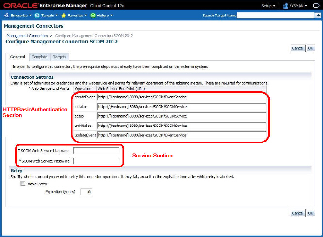
Example 2-9 shows the information that is included in the Authentication section. In this example, the authentication method is basic authentication. The operator would be required to provide SCOM Web Service Username and SCOM Web Service Password values when configuring the connector. The values entered by the operator would be passed in the basic authentication header for any requests that are sent to the web service.
Example 2-9 Authentication Section Sample
<HTTPBasicAuthentication>
  <Username required="true">
    <VariableName>Username</VariableName>
    <DisplayName>SCOM Web Service Username</DisplayName>
  </Username>
  <Password required="true">
    <VariableName>Password</VariableName>
    <DisplayName>SCOM Web Service Password</DisplayName>
  </Password>
</HTTPBasicAuthentication>
2.5.3.6 Service Section
This section is used to configure the URLs used to connect to the web service for the different service operations. Each entry that is defined in this section must also define the corresponding templates in the Template Registration section. There must be a separate Service section entry for each of the following operations:
-
createEvent -
updateEvent
The following service operations are optional:
-
setup -
initialize -
uninitialize -
cleanup
Note:
The service names in the connector descriptor should exactly match the names defined above and are case sensitive.
Table 2-8 lists the fields in the section and provides an explanation of each field:
Table 2-8 Service Fields
| Section/Field | Required | Description | |
|---|---|---|---|
|
Service |
Yes |
This section allows you to specify configurations specific to the External System's web services. |
|
|
Method |
Yes |
Method defines one of the EM-specific service operation names. For event connectors, it must be set to one of the following values: setup initialize createEvent updateEvent uninitialize cleanup A cleanup request template can be defined but not a cleanup response template. |
|
|
WebServiceEndpoint |
Yes |
This field specifies the default web service endpoint string to be displayed in the web service section of the Management Connector page. |
|
|
SOAPAction |
No |
The SOAPAction to specify when calling the web service |
|
|
SOAPBindingType |
No |
Possible values are: SOAP11HTTP_BINDING SOAP12HTTP_BINDING SOAP11HTTP_MTOM_BINDING SOAP12HTTP_MTOM_BINDING |
|
2.5.3.7 Sample Service Section
Example 2-10 shows both of the required Service sections and three optional sections. The URLs in the WebServiceEndpoint element are placed in a CDATA section to avoid conflicts with reserved XML characters. The values surrounded by square brackets [] need to be replaced by the operator on the configuration page.
For example, the default URL for the createEvent operation is:
http://<host name>:8080/services/SCOM/EventService
This value will be displayed in the Web Service End Points section of the configuration page next to the createEvent operation. The operator will need to replace <host name> with the host name or IP address of the system where the web service is hosted.
Example 2-10 Service Section Sample
<Service>
    <Method>setup</Method>
    <WebServiceEndpoint>
      <![CDATA[http://<host name>:8080/services/SCOM/SCOMService]]>
    </WebServiceEndpoint>
    <SOAPAction>setup</SOAPAction>
    <SOAPBindingType>SOAP11HTTP_BINDING</SOAPBindingType>
</Service>
<Service>
    <Method>initialize</Method>
    <WebServiceEndpoint>
      <![CDATA[http://<host name>:8080/services/SCOM/SCOMService]]>
    </WebServiceEndpoint>
    <SOAPAction>initialize</SOAPAction>
    <SOAPBindingType>SOAP11HTTP_BINDING</SOAPBindingType>
</Service>
<Service>
    <Method>createEvent</Method>
    <WebServiceEndpoint>
      <![CDATA[http://<host name>:8080/services/SCOM/EventService]]>
    </WebServiceEndpoint>
    <SOAPAction>createEvent</SOAPAction>
    <SOAPBindingType>SOAP11HTTP_BINDING</SOAPBindingType>
</Service>
<Service>
    <Method>updateEvent</Method>
    <WebServiceEndpoint>
      <![CDATA[http://<host name>:8080/services/SCOM/EventService]]>
    </WebServiceEndpoint>
    <SOAPAction>updateEvent</SOAPAction>
    <SOAPBindingType>SOAP11HTTP_BINDING</SOAPBindingType>
</Service>
<Service>
    <Method>uninitialize</Method>
    <WebServiceEndpoint>
      <![CDATA[http://<host name>:8080/services/SCOM/SCOMService]]>
    </WebServiceEndpoint>
    <SOAPAction>uninitialize</SOAPAction>
    <SOAPBindingType>SOAP11HTTP_BINDING</SOAPBindingType>
</Service>
2.5.3.8 Template Registration Section
This section is used to define all of the templates that were built in the previous chapter. Table 2-9 lists the fields in the section and provides an explanation of each field.
Table 2-9 Template Registration Fields
| Section/Field | Required | Description | |
|---|---|---|---|
|
TemplateRegistration |
Yes |
This section defines up to 50 connector templates. Each template that you created in Developing Required Template Files needs to be defined here. |
|
|
FileName |
Yes |
Name of the file that defines the template. |
|
|
InternalName |
Yes |
Internal template name. It must be set to one of the following service method names. It is case sensitive so it must match exactly. setup initialize createEvent updateEvent uninitialize cleanup |
|
|
TemplateName |
Yes |
Name to use in the UI when referencing this template. |
|
|
TemplateType |
Yes |
There are two types of templates. One is Outbound and the other is Inbound. Outbound is used to generate XML that is being sent to the external web service and Inbound is used to transform incoming XML to the format expected by Enterprise Manager. Possible values for the template type are: InboundXSL OutboundXSL OutboundXML |
|
|
Description |
Yes |
Description of the template that will be displayed at the UI. |
|
2.5.3.9 Sample Template Registration Section
Example 2-11 shows the different TemplateRegistration sections:
Example 2-11 Template Registration Section Sample
<TemplateRegistration>
    <FileName>setup_request.xml</FileName>
    <InternalName>setup</InternalName>
    <TemplateName>Setup Request</TemplateName>
    <TemplateType>OutboundXML</TemplateType>
    <Description>This is the request xml file for the setup method</Description>
</TemplateRegistration>
<TemplateRegistration>
    <FileName>setup_response.xsl</FileName>
    <InternalName>setup</InternalName>
    <TemplateName>Setup Response</TemplateName>
    <TemplateType>InboundXSL</TemplateType>
    <Description>This is the response xsl file for the setup method</Description>
</TemplateRegistration>
<TemplateRegistration>
    <FileName>setup_request.xml</FileName>
    <InternalName>initialize</InternalName>
    <TemplateName>Initialize Request</TemplateName>
    <TemplateType>OutboundXML</TemplateType>
    <Description>This is the request xml file for the initialize method</Description>
</TemplateRegistration>
<TemplateRegistration>
    <FileName>createEvent_request_2012.xsl</FileName>
    <InternalName>createEvent</InternalName>
    <TemplateName>Create Event Request</TemplateName>
    <TemplateType>OutboundXSL</TemplateType>
    <Description>This is the request xsl file for the createEvent method</Description>
</TemplateRegistration>
<TemplateRegistration>
    <FileName>createEvent_response.xsl</FileName>
    <InternalName>createEvent</InternalName>
    <TemplateName>Create Event Response</TemplateName>
    <TemplateType>InboundXSL</TemplateType>
    <Description>This is the response xsl file for the createEvent method</Description>
</TemplateRegistration>
<TemplateRegistration>
    <FileName>updateEvent_request_2012.xsl</FileName>
    <InternalName>updateEvent</InternalName>
    <TemplateName>Update Event Request</TemplateName>
    <TemplateType>OutboundXSL</TemplateType>
    <Description>This is the request xsl file for the updateEvent method</Description>
</TemplateRegistration>
<TemplateRegistration>
    <FileName>updateEvent_response.xsl</FileName>
    <InternalName>updateEvent</InternalName>
    <TemplateName>Update Event Response</TemplateName>
    <TemplateType>InboundXSL</TemplateType>
    <Description>This is the response xsl file for the updateEvent method</Description>
</TemplateRegistration>
<TemplateRegistration>
    <FileName>cleanup_request.xml</FileName>
    <InternalName>uninitialize</InternalName>
    <TemplateName>Uninitialize Request</TemplateName>
    <TemplateType>OutboundXML</TemplateType>
    <Description>This is the request xml file for the uninitialize method</Description>
</TemplateRegistration>
2.5.3.10 Complete Event Connector Deployment File
Example C-1 in Event Connector Samples shows the complete connector deployment file that includes the samples shown in the preceding sections. Figure 2-1 shows an example of the connector configuration page that is displayed for the sample deployment file. The image has been labeled to show where the fields were defined in the deployment file.
Figure 2-1 Complete Connector Deployment Page
2.6 Packaging and Deploying the Event Connector
To deploy the connector, Enterprise Manager uses the Self Update feature. This feature, which can be accessed through the console, provides the ability to import the connector into the Enterprise Manager environment. To deploy the connector complete the following:
-
Prepare the connector jar file
Package all XML and XSLT template files as a .jar file
<name>_connector.jar ---> connectorDeploy.xml --->template1.xml --->template2.xsl ….. ….. --->templateN.xsl -
Prepare the manifest file
Table 2-10 lists the Key attributes of self update manifest files:
Table 2-10 Self Update Manifest File Attributes
Name Description EntityType
Value is core_connector
EntityTypeVersion
Current release version. Value=12.1.0.1.0
Version
Version number of the connector. Must be set to the value specified in the
ManagementConnector/Versionnode in theconnectorDeploy.xmlfile.Attribute @Name=connector_type
Connector type name. Must be set to the value specified in the
ManagementConnector/Namenode in theconnectorDeploy.xmlfileAttribute @Name=connector_category
Category type can be TicketingConnector or EventConnector
ArchiveList
This element contains the list of archives that are part of connector setup. Generally there will be single connector jar but for some special implementation there may be additional jars(adapter or agent). In these cases, the connector specific jar should be first one in the defined list. This is mandatory requirement.
The
SelfUpdateManifest.xsdschema file defines the format of the manifest file.See Table 2-2 in the Extracting Schema Files section for the location of the
SelfUpdateManifest.xsdschema file.The following example shows the code for the
connector_manifest.xmlfile: -
Configure the
emedktoolThe
emedktool can be configured by following instructions from the Enterprise Manager user interface. From the Setup menu, select Extensibility, then Development Kit. -
Prepare the self-update archive
This requires the connector jar file and the manifest file for the connector. To prepare self-update, call the following utility to create a self update archive file:
edkutil prepare_update
        -manifest "manifest xml"
        -archivedir "archives directory"
        -out "output file or directory"
        [-typexml "update type xml"]
Table 2-11 describes the options available with the utility:
Table 2-11 Self Update Utility Options
Option Description -manifest
Self update manifest file that describes the update.
-archivedir
Directory containing the archive files specified in the manifest file.
-out
Directory or filename for the self update archive. If a directory is specified, the filename is autogenerated.
-typexml
Optional path to the update type xml
The following example creates a self update archive in the
/u01/sardirectory based on the manifest file/u01/connector/connector_manifest.xml. The archives referred to in connector_manifest.xml are picked from the directory/u01/connector/archives.edkutil prepare_update -manifest /u01/connector/connector_manifest.xml -archivedir /u01/connector/archives -out /u01/sar/sample_connector.zip -
Import the connector archive to Enterprise Manager by calling any one of the following emcli commands:
     emcli import_update
  -file=\ file\
  -omslocal
or
     emcli import_update
-file=\ file\
-host=\ host name\
[-credential_set_name=\ setname\ ] | -credential_name=\ name\  -credential_owner=\ owner\
These commands import a Self Update archive file into Enterprise Manager. On successful import, the update is displayed on the Self Update Home in downloaded status for further action. Table 2-12 describes the connector archive command options.
Table 2-12 Connector Archive Command Options
Options Description -file
The complete path name of the update archive file
-omslocal
The flag specifying that the file is accessible from the OMS
-host
The target name for a host target where the file is available
-credential_set_name
The set name of the preferred credential stored in the repository for the host target. Can be one of the following:
-
HostCredsNormalDefault unprivileged credential set
-
HostCredsPrivPrivileged credential set
-credential_name
The name of a named credential stored in the repository. This option must be specified along with -credential_owner option.
-credential_owner
The owner of a named credential stored in the repository. This option must be specified along with -credential_name option.
The following paragraphs provide some examples of the use of the
emclicommand:Example 1
Imports the file
update1.zip. The file must be present on the OMS host. In a multiple OMS setup, the request can be processed by any OMS, so the file should be accessible from the OMS processing the request. This usually means that the file must be kept on a shared location that is accessible from all OMS.emcli import_update -file=\ /u01/common/update1.zip\ -omslocal
Example 2
Imports the file
update1.zipthat is present on thehost1.example.comhost. The host must be a managed host target in Enterprise Manager and the agent on this host must be up and running. The preferred unprivileged credentials for hosthost1.example.comare used to retrieve the remote file.emcli import_update -file=\ /u01/common/update1.zip\ -host=\ host1.example.com\ -credential_set_name=\ HostCredsNormal\
Example 3
Imports the file
update1.zipthat is present on thehost1.example.comhost. The host must be a managed host target in Enterprise Manager and the agent on this host must be up and running. The named credentials\ host1_creds\owned by user\ admin1\are used to retrieve the remote file.emcli import_update -file=\ /u01/common/update1.zip\ -host=\ host1.example.com\ -credential_name=\ host1_creds\ -credential_owner=\ admin1\
-
-
Apply the connector using one of the following methods:
-
From the Cloud Control console:
-
Go to Self-Update Home page. The connector will be shown as downloaded.
-
Select the connector row and click Apply to deploy the connector.
-
-
From the command line, run the following
emcli listcommand to determine the identifier of the connector that was just imported:emcli list -resource=Updates -bind="et_name = 'core_connector'"
The output of the command would look like this example:
Status    Category          Type                Version      Id
-------   ----------   ------------------  ----------   --------------
Applied   Ticketing    Remedy Service      12.1.0.1.0   123456789ABCDE
          Connector    Desk Connector
Applied   Event        HP OMU Connector    12.1.0.3.0   11223344AABBCC
          Connector
Applied   Ticketing    Remedy Service      12.1.0.3.0   1A2B3C4D5E6F7G
          Connector    Desk 7.6 Connector
Applied   Ticketing    CASD Connector      12.1.0.3.0   55443322CCBBAA
          Connector
Note the ID for the connector that was just imported. You will need to select the ID for the connector that was just imported and supply to the
emcli apply_updatescommand listed below:emcli apply_updates -id=<ID>
-
Example 2-12 Manifest File Sample
<EntityInstanceList xmlns="http://www.oracle.com/EnterpriseGridControl/SelfUpdateManifest/">
    <EntityInstance xmlns="http://www.oracle.com/EnterpriseGridControl/SelfUpdateManifest/"
        EntityTypeVersion="12.1.0.1.0" EntityType="core_connector" Maturity="PRODUCTION"
        Vendor="Oracle" PluginID="oracle.sysman.core">
        <Description>
            <![CDATA[ Microsoft SCOM 2012 Connector - 12.1.0.1.0 ]]>
        </Description>
        <AttributeList>
            <Version>12.1.0.1.0</Version>
            <Attribute Name="connector_type" Value="SCOM 2012 Connector" Label="SCOM 2012 Connector"/>
            <Attribute Name="connector_category" Value="EventConnector" Label="Event Connector"/>
        </AttributeList>
        <Readme><![CDATA[
The Oracle Management Connector for Microsoft System Center Operations Manager (SCOM) 2012 enables you to forward Enterprise Manager alerts to SCOM 2012. The integration is a uni-directional connection so information only flows from Enterprise Manager to SCOM. State changes in Enterprise Manager are reflected in SCOM. However, if you change the state of the alert in SCOM, the change is not reflected in Enterprise Manager.
The connector requires the installation of an Oracle SCOM agent on a Windows system with connectivity to the RMS server system. In addition to the agent, an Oracle SCOM Web Service must also be installed. The web service must be installed on a system that has connectivity to the system where the agent is installed and the Enterprise Manager server system. The web service is Java based and can be installed on any Windows or UNIX platform that supports Oracle JRE version 6.
This connector only supports SCOM 2012. There is a separate connector that must be used with versions of SCOM 2007.
Some configuration changes are required in SCOM to allow alerts to be created by Enterprise Manager. A management pack must be imported and an account must be set up that can be used to access the SCOM API.

Change Logs:

  12.1.0.1.0
   - Initial Release


        ]]></Readme>
        <DependsOn/>
        <ArchiveList>
            <Archive Filename="scom_2012_connector.jar" IsMDS="false"/>
            <Archive Filename="SCOM_webservices_adapter.jar" />
            <Archive Filename="SCOM2012Agent.zip" />
            <Archive Filename="SCOMNotification.zip" />
        </ArchiveList>
        <CustomData></CustomData>
    </EntityInstance>
</EntityInstanceList>