IDN Connectors
This section describes ports that are used to drive MICROS IDN Printers.
All MICROS Workstation contain at least one 8-pin modular port designated for driving IDN devices.
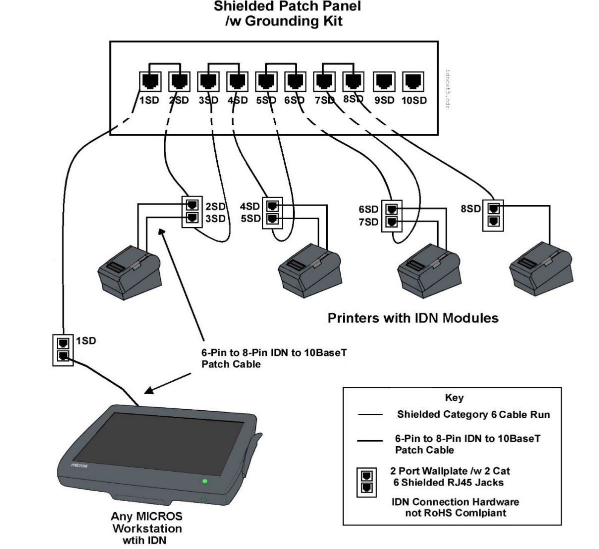
The figure below is an example of driving a small network of IDN printers from any Workstation with an IDN port using shielded category 6 or better cable and connection hardware.
In this figure, the workstation driving IDN printers is shown at the left of the illustration. One 8-Pin to 6-Pin IDN patch cable is connected between the 8-pin IDN ports on the workstation to one of the 6- pin connectors on the local module.
A Patch cable is then installed between the remaining 6-pin connector on local IDN printer and the faceplate connector to convert the IDN transmit/receive pairs into ANSI/TIA/EIA-568-A compatible transmit/receive pairs.
Install a pair of Cat 6 or better shielded cables between the patch panel and the two connectors on the wall plate near each printer location. The ‘dual run’ to the faceplate is required to obtain cable certification since a daisy chain configuration is not part of Ethernet topology. Terminate the drain wire of each cable run at the patch panel.
To maintain the IDN daisy chain, install Category 6 or better patch cables at the patch panel. At each remote printer location, install a pair of patch cables to maintain the daisy chain at the printers. The last printer in the chain requires only one patch cable.
Figure 31-1 MICROS Workstation Driving IDN Printers over Shielded Cabling

Parent topic: Shielded Cable and Connection Hardware for IDN