A Servicing the Oracle Database Appliance Version 1
This appendix describes how to prepare Oracle Database Appliance Version 1 for servicing. The Oracle Database Appliance Version 1 is also referred to as "original version" or "V1".
This appendix does NOT apply to Oracle Database Appliance X3-2, Oracle Database Appliance X4-2, Oracle Database Appliance X5-2, Oracle Database Appliance X6 series, or Oracle Database Appliance X7 series. Refer to the preceding chapters in this document for information on servicing those systems.
The following topics are included:
Preparing to Service
This section describes how to prepare Oracle Database Appliance Version 1 for servicing. If you have Oracle Database X6-2 series, go to Preparing Oracle Database Appliance X6-2 Series for Service. If you have Oracle Database Appliance X3-2, Oracle Database Appliance X4-2, or Oracle Database Appliance X5-2, go to Preparing Oracle Database Appliance X3-2/X4-2/X5-2 for Service.
Component Replacement Policy (CRUs and FRUs)
Note:
Information in this appendix does NOT apply to Oracle Database Appliance X3-2, Oracle Database Appliance X4-2, Oracle Database Appliance X5-2 or Oracle Database Appliance X6 series. Refer to the preceding chapters in this document for information on servicing those systems.The replaceable components in your Oracle Database Appliance Version 1 are designated as either field-replaceable units (FRUs) or customer-replaceable units (CRUs). Some can be replaced with the power on, some require the powering off of a server node, and some require the powering off of the entire system chassis.
-
A part designated as a FRU must be replaced by Oracle-qualified service technician.
-
A part designated as a CRU can be replaced by a person who is not an Oracle-qualified service technician.
The following table lists replaceable components, their service designation (CRU or FRU), and the system power policy related to servicing the component.
| Component | Policy |
|---|---|
|
Storage drives and boot drives (CRU) |
Hot-pluggable – Can be removed and replaced when the system is powered on. |
|
Fan modules (CRU) |
Hot-pluggable – Can be removed and replaced when the system is powered on. |
|
Power supplies (CRU) |
Hot-pluggable – Can be removed and replaced when the system is powered on. |
|
Air duct (FRU) |
Cold service, server node – Can only be removed and replaced when the server node is powered off. The other server node and the system chassis can remain on. |
|
DIMMs (CRU) |
Cold service, server node – Can only be removed and replaced when the server node is powered off. The other server node and the system chassis can remain on. |
|
PCIe risers (CRU) |
Cold service, server node – Can only be removed and replaced when the server node is powered off. The other server node and the system chassis can remain on. |
|
PCIe cards (CRU) |
Cold service, server node – Can only be removed and replaced when the server node is powered off. The other server node and the system chassis can remain on. |
|
Boot disk backplane (FRU) |
Cold service, server node – Can only be removed and replaced when the server node is powered off. The other server node and the system chassis can remain on. |
|
Server node battery (CRU) |
Cold service, server node – Can only be removed and replaced when the server node is powered off. The other server node and the system chassis can remain on. |
|
Processors (CPUs) (FRU) |
Cold service, server node – Can only be removed and replaced when the server node is powered off. The other server node and the system chassis can remain on. |
|
Motherboard (FRU) |
Cold service, server node – Can only be removed and replaced when the server node is powered off. The other server node and the system chassis can remain on. |
|
Server node internal cables (FRU) |
Cold service, server node – Can only be removed and replaced when the server node is powered off. The other server node and the system chassis can remain on. |
|
Power distribution board (FRU) |
Cold service, system chassis – Servicing this component requires that the power be completely removed from the system chassis (both server nodes powered off). |
|
Disk midplane module (FRU) |
Cold service, system chassis – Servicing this component requires that the power be completely removed from the system chassis (both server nodes powered off). |
|
Disk midplane module HDD cable (FRU) |
Cold service, server node – Can only be removed and replaced when the server node is powered off. The other server node and the system chassis can remain on. |
|
Front indicator panels (FRU) |
Cold service, system chassis – Servicing this component requires that the power be completely removed from the system chassis (both server nodes powered off). |
Safety Information
Note:
Information in this appendix does NOT apply to Oracle Database Appliance X3-2, Oracle Database Appliance X4-2, Oracle Database Appliance X5-2 or Oracle Database Appliance X6 series. Refer to the preceding chapters in this document for information on servicing those systems.This section provides important safety information. Read it before servicing Oracle Database Appliance.
Caution:
Hazardous voltage present. Never run the system with the top cover removed.Caution:
Equipment damage. Install the system top cover properly before starting the system.For your protection, observe the following safety precautions when setting up your equipment:
-
Follow all cautions, warnings, and instructions marked on the equipment and described in Important Safety Information for Oracle's Hardware Systems and Oracle Database Appliance Safety and Compliance Guide.
-
Ensure that the voltage and frequency of your power source match the voltage and frequency inscribed on the equipment's electrical rating label.
-
Follow the electrostatic discharge safety practices as described in this chapter.
Required Tools
Note:
Information in this appendix does NOT apply to Oracle Database Appliance X3-2, Oracle Database Appliance X4-2, Oracle Database Appliance X5-2 or Oracle Database Appliance X6 series. Refer to the preceding chapters in this document for information on servicing those systems.Oracle Database Appliance can be serviced with the following tools:
-
Antistatic wrist strap
-
Antistatic mat
-
No. 2 10-inch Phillips screwdriver (magnetic tip recommended)
-
Flat blade screwdriver
-
Stylus or pencil (to press the Clear CMOS button)
Obtaining the Chassis Serial Number
Note:
Information in this appendix does NOT apply to Oracle Database Appliance X3-2, Oracle Database Appliance X4-2, Oracle Database Appliance X5-2 or Oracle Database Appliance X6 series. Refer to the preceding chapters in this document for information on servicing those systems.To obtain support for Oracle Database Appliance Version 1, you need to report your product serial number. The product serial number is located on an RFID tag on the front of the system and on the Customer Information Sheet that is included with the system.
Shutting Down a Server Node and Powering Off the System
Note:
Information in this appendix does NOT apply to Oracle Database Appliance X3-2, Oracle Database Appliance X4-2, Oracle Database Appliance X5-2 or Oracle Database Appliance X6 series. Refer to the preceding chapters in this document for information on servicing those systems.You can shut down either Oracle Database Appliance Version 1 server node using the front panel power button, or Oracle ILOM. Each method provides a graceful shutdown and an emergency shutdown option.
Caution:
Data loss. To avoid data loss and file system corruption, always use a graceful shutdown unless it is an emergency.Note:
To use Oracle ILOM to shut down a server node, ensure that you have performed its initial configuration as described in "Connecting and Configuring Oracle ILOM" in the Oracle Database Appliance Getting Started Guide.After you have shut down the server nodes, you can power off the system.
See the following topics in this section to shut down a server node and power off the system chassis:
Shut Down a Server Node
Note:
Information in this appendix does NOT apply to Oracle Database Appliance X3-2, Oracle Database Appliance X4-2, Oracle Database Appliance X5-2 or Oracle Database Appliance X6 series. Refer to the preceding chapters in this document for information on servicing those systems.You must shut down the server node before you remove it from the system chassis.
- To shut down a server node using the Power button, perform one of the following:
-
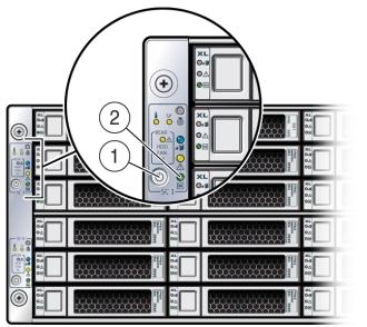
Graceful shutdown: Press and release the recessed Power button on the lower left-hand corner of the server node's front panel (see the following figure [1]). This causes Advanced Configuration and Power Interface (ACPI) to perform an orderly shutdown of the system.
-
Emergency shutdown: Press and hold the recessed Power button on the lower left-hand corner of the server node's front panel for at least five seconds until the main power is off and the server node enters standby power mode (see the following figure [1]).
Caution:
Data loss. To avoid data loss and file system corruption, always use a graceful shutdown unless it is an emergency.
When the server node is shut down, the Power/OK LED [2] on the server node's front panel flashes, indicating that the server node is in standby power mode.
-
- To shut down a server node using the Oracle ILOM, perform one of the following:
- Using the Oracle ILOM web interface:
- Open a browser and enter the server node's service processor IP address in the browser's address field.
- At the log in page, type a user name (the account must have Reset and Host Control (r) privileges) and password, and click the Log In button.
- Go to Remote Power Control and do one of the following:
-
Select Graceful Shutdown and Power Off from the Select Action list box and then click Save and OK.
The server node shuts down gracefully.
-
Select Immediate Power Off from the Select Action list box and then click Save and OK.
The server node shuts down immediately.
Caution:
Data loss. To avoid data loss and file system corruption, use graceful shutdown unless it is an emergency.
-
- Using the Oracle ILOM CLI:
- Log in to Oracle ILOM using an ssh client. Type:
$ssh username@sp_ip_address
Where username is a user account name with Reset and Host Control (r) privileges and sp_ip_address is the IP address of the server node service processor.
- When prompted, enter the user account password.
- Enter the command to shut down the server node:
-
For a graceful shutdown, type:
-> stop /SYS
The server node shuts down gracefully.
-
For an emergency shutdown, type:
-> stop -f /SYS
The server node shuts down immediately.
Caution:
Data loss. To avoid data loss and file system corruption, use graceful shutdown unless it is an emergency.
-
- Log in to Oracle ILOM using an ssh client. Type:
- Using the Oracle ILOM web interface:
Power Off the System
Note:
Information in this appendix does NOT apply to Oracle Database Appliance X3-2, Oracle Database Appliance X4-2, Oracle Database Appliance X5-2 or Oracle Database Appliance X6 series. Refer to the preceding chapters in this document for information on servicing those systems.The appliance database must be shut down before powering off the system chassis.
- Shut down both server nodes.
Shutting down both server nodes places the system in standby power mode.
- Disconnect the AC power cords from the system.
Disconnecting the power cords from the system removes all power from the system.
Performing Electrostatic Discharge and Antistatic Prevention Measures
Note:
Information in this appendix does NOT apply to Oracle Database Appliance X3-2, Oracle Database Appliance X4-2, Oracle Database Appliance X5-2 or Oracle Database Appliance X6 series. Refer to the preceding chapters in this document for information on servicing those systems.Electrostatic discharge (ESD) sensitive devices, such as the motherboards, PCIe cards, storage drives, and memory cards, require special handling.
Caution:
Equipment damage. Follow antistatic precautions and do not touch the components along their connector edges.-
Attach an antistatic strap to your wrist and then to a metal area on the chassis. Following this practice equalizes the electrical potential between you and the system.
Note:
An antistatic wrist strap is not included in the system Accessory Kit. However, antistatic wrist straps are included with some options and components. -
Place ESD-sensitive components on an antistatic mat. The following items can be used as an antistatic mat:
-
Antistatic bag used to wrap a replacement part
-
ESD mat
-
Disposable ESD mat (shipped with some replacement parts or optional system components)
-
When handling components such as storage drive assemblies, circuit boards, or PCIe cards:
Removing Server Nodes From the System Chassis
Note:
Information in this appendix does NOT apply to Oracle Database Appliance X3-2, Oracle Database Appliance X4-2, Oracle Database Appliance X5-2 or Oracle Database Appliance X6 series. Refer to the preceding chapters in this document for information on servicing those systems.You must remove the Oracle Database Appliance Version 1 server node from the chassis to remove or replace internal server node components.
Remove a Server Node From the System Chassis
Note:
Information in this appendix does NOT apply to Oracle Database Appliance X3-2, Oracle Database Appliance X4-2, Oracle Database Appliance X5-2 or Oracle Database Appliance X6 series. Refer to the preceding chapters in this document for information on servicing those systems.The removal procedure is the same for both server nodes. Note that you do not need to remove the entire system chassis from the rack to perform service procedures on a server node.
Note:
Replacing a server node FRU with a new server node is a service activity that must be performed by an Oracle-qualified service technician. The customer may remove the server node to service other CRU components in the server node.- Shut down the server node.
Caution:
Data loss. To avoid data loss and file system corruption, always use a graceful shutdown unless it is an emergency. - To unseat the server node from the system chassis, pull the two latches on the rear of the server node down [1].
The latches are marked by green tabs. Pull the latches down and away from the rear to the system.
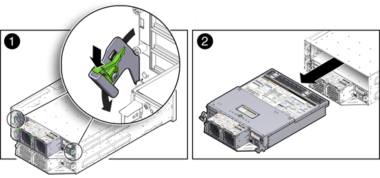
- Slide the server node to the rear and lift it out of the system [2].
Removing the Server Node Top Cover
Note:
Information in this appendix does NOT apply to Oracle Database Appliance X3-2, Oracle Database Appliance X4-2, Oracle Database Appliance X5-2 or Oracle Database Appliance X6 series. Refer to the preceding chapters in this document for information on servicing those systems.To gain access to a most of Oracle Database Appliance Version 1 server node's internal components, you must remove the server node's top cover.
Remove the Server Node Top Cover
Note:
Information in this appendix does NOT apply to Oracle Database Appliance X3-2, Oracle Database Appliance X4-2, Oracle Database Appliance X5-2 or Oracle Database Appliance X6 series. Refer to the preceding chapters in this document for information on servicing those systems.- Remove the server node from the system chassis.
- Remove the top cover.
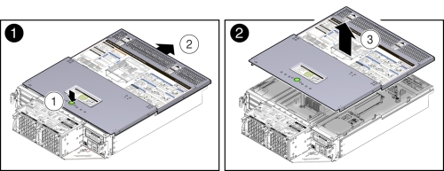
- To unlatch the server node top cover, press and hold the green release button on the top of the server node cover [1].
- Using the indented area near the green release button, slide the cover toward the front of the server node about 0.5 inches (12.7 mm) [1].
- Lift the cover up and remove it [2].
Removing the Middle Section of the System Top Cover
Note:
Information in this appendix does NOT apply to Oracle Database Appliance X3-2, Oracle Database Appliance X4-2, Oracle Database Appliance X5-2 or Oracle Database Appliance X6 series. Refer to the preceding chapters in this document for information on servicing those systems.To gain access to the Oracle Database Appliance Version 1 power distribution board and the disk midplane board you must remove the middle section of the system's top cover.
Remove the Middle Section of System Top Cover
Note:
Information in this appendix does NOT apply to Oracle Database Appliance X3-2, Oracle Database Appliance X4-2, Oracle Database Appliance X5-2 or Oracle Database Appliance X6 series. Refer to the preceding chapters in this document for information on servicing those systems.- Power down the server nodes and remove the power cords from the power supplies.
For instructions, see Shut Down a Server Node.
Caution:
System fault. Do not remove the middle section of the system cover while the AC power cords are connected. Otherwise the fault LEDs light and a system fault is logged. - Remove the middle section of the system top cover.
To remove the middle section of the system's top cover, remove the captive Phillips screws that secure it to the system.
Caution:
Hazardous voltage present. Never run the system with the middle section of the system top cover removed.Caution:
Equipment damage. Install the system top cover properly before starting the system.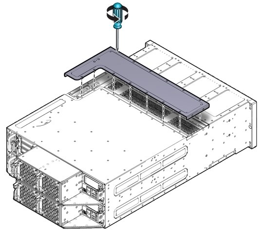
Servicing Hot-Pluggable Components
This section describes replacing hot-pluggable components for the Oracle Database Appliance Version 1. If you have Oracle Database Appliance X6-2 series, go to Oracle Database Appliance X6-2 Series Server Node Hot-Pluggable Components. If you have Oracle Database Appliance X3-2, Oracle Database Appliance X4-2, or Oracle Database Appliance X5-2, go to Oracle Database Appliance X3-2/X4-2/X5-2 Server Node Hot-Pluggable Components or Oracle Database Appliance X3-2/X4-2/X5-2 and X6-2-HA/X7-2-HA Storage Shelf Hot-Pluggable Components.
In Oracle Database Appliance Version 1, the following devices are hot-pluggable:
-
Storage and Boot Drives. See Servicing Storage Drives and Boot Drives (CRU).
-
Fan modules. See Servicing Fan Modules (CRU).
-
Power supplies. See Servicing Power Supplies (CRU).
Note:
After a physical insertion or removal action of a storage component (such as a disk or SAS cable), you should wait before performing the next action to allow the system software to fully process the event. This could take up to 3 minutes to complete.Note:
For the Oracle Database Appliance Version 1, you must run the oakcli add disk -local command after replacing a failed disk. Refer to the Administration and Reference Guide for details.Servicing Storage Drives and Boot Drives (CRU)
Note:
Information in this appendix does NOT apply to Oracle Database Appliance X3-2, Oracle Database Appliance X4-2, Oracle Database Appliance X5-2 or Oracle Database Appliance X6 series. Refer to the preceding chapters in this document for information on servicing those systems.Oracle Database Appliance Version 1 has 24 storage drives, located in the front of the chassis, and each server node has 2 boot drives, located in the rear. All storage drives and boot drives are hot-pluggable.
See Storage and Boot Drive Status Indicators for specific information about drive status LEDs.
This section includes:
Storage and Boot Drive Locations
Appliance storage drives. Appliance storage drives are installed at the front of Oracle Database Appliance Version 1. Drive numbering is listed on the drive label on the right side of the appliance [1].
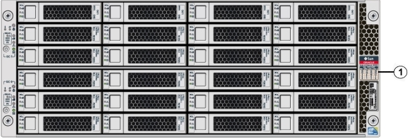
The following table shows slot numbering and the type of the storage drive supported in each slot.
Note:
The appliance might include both mechanical hard disk (HDD) and solid state (SSD) drives. Both use the same 2.5 inch disk drive bracket. An SSD has a smaller footprint inside of the bracket than an HDD.| Drive Slot Numbers and Types Supported | Drive Slot Numbers and Types Supported | Drive Slot Numbers and Types Supported | Drive Slot Numbers and Types Supported |
|---|---|---|---|
|
SSD20 |
SSD21 |
SSD22 |
SSD23 |
|
HDD16 |
HDD17 |
HDD18 |
HDD19 |
|
HDD12 |
HDD13 |
HDD14 |
HDD15 |
|
HDD8 |
HDD9 |
HDD10 |
HDD11 |
|
HDD4 |
HDD5 |
HDD6 |
HDD7 |
|
HDD0 |
HDD1 |
HDD2 |
HDD3 |
Server Node boot drives. Each appliance server node contains two boot drives that are installed in the back of Oracle Database Appliance and identified on the rear drive panel label.
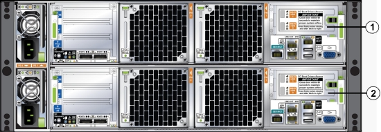
The following table shows the location and numbering of the boot drives.
| Callout | Drive Locations and Identification |
|---|---|
|
1 |
Boot Drives at the back of server node 1. Location and identification of the server node 1 boot drives as listed in Oracle ILOM:
|
|
2 |
Boot Drives at the back of server node 0. Location and identification of the server node 0 boot drives as listed in Oracle ILOM:
|
Remove a Storage Drive
Note:
Information in this appendix does NOT apply to Oracle Database Appliance X3-2, Oracle Database Appliance X4-2, Oracle Database Appliance X5-2 or Oracle Database Appliance X6 series. Refer to the preceding chapters in this document for information on servicing those systems.This section describes removing a storage drive from Oracle Database Appliance Version 1.
- Identify the storage drive that you want to remove.
If a drive has failed, its amber Service Required LED will be lit. For information on drive status LEDs, see Storage and Boot Drive Status Indicators. For specific drive locations, see Storage and Boot Drive Locations.
- Remove a storage drive.
- On the drive you plan to remove, push the storage drive release button to open the latch [1].
- Grasp the latch and open it to a 45 degree angle [2].
- Using the latch, slowly pull the drive straight out of the drive slot, not sideways or vertically.
Do not use much force on the latch when removing the drive.
Caution:
Equipment damage. Do not use the latch as an ejector. Do not bend it too far to the right.Caution:
Equipment damage. Always replace a drive with another drive to maintain proper airflow.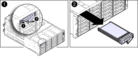
Install Storage Drive
Note:
Information in this appendix does NOT apply to Oracle Database Appliance X3-2, Oracle Database Appliance X4-2, Oracle Database Appliance X5-2 or Oracle Database Appliance X6 series. Refer to the preceding chapters in this document for information on servicing those systems.This section describes installing a storage drive in Oracle Database Appliance Version 1.
- Determine the drive slot location for the replacement drive.
Drives are physically addressed according to the slot in which they are installed. See Storage and Boot Drive Locations for drive locations.
- Slide the drive into the drive slot until it is fully seated.
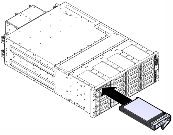
- Close the latch to lock the drive in place.
- Run the fwupdate command and verify that it lists all the disks under the DISKS section.
Remove a Boot Drive
Note:
Information in this appendix does NOT apply to Oracle Database Appliance X3-2, Oracle Database Appliance X4-2, Oracle Database Appliance X5-2 or Oracle Database Appliance X6 series. Refer to the preceding chapters in this document for information on servicing those systems.This section describes removing a boot drive from Oracle Database Appliance Version 1.
- Identify the boot drive that you want to remove.
The amber Service Required LED might be lit. For specific drive locations, see Storage and Boot Drive Locations.
- Remove the boot drive.
- To open the drive door, slide the latch to the left.
- Pull the door open [2].
- On the drive you plan to remove, push the storage drive release button to open the latch [2].
- Grasp the latch and open it to a 45 degree angle [2].
- Using the latch, slowly pull the drive straight out of the drive slot, not sideways or vertically [2].
Do not use much force on the latch when removing the drive.
Caution:
Equipment damage. Do not use the latch as an ejector. Do not bend it too far to the right.Caution:
Equipment damage. Close the door after removing a boot drive to prevent overheating due to improper airflow.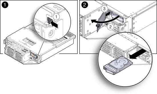
Install a Boot Drive
Note:
Information in this appendix does NOT apply to Oracle Database Appliance X3-2, Oracle Database Appliance X4-2, Oracle Database Appliance X5-2 or Oracle Database Appliance X6 series. Refer to the preceding chapters in this document for information on servicing those systems.This section describes installing a boot drive in Oracle Database Appliance Version 1.
- Determine the drive slot location for the replacement drive.
Drives are physically addressed according to the slot in which they are installed. See Storage and Boot Drive Locations for drive locations.
- Pull open the rear drive door.
- Slide the drive into the drive slot until it is fully seated [1].
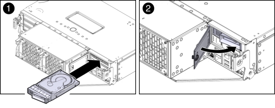
- Close the drive latch to lock the drive in place.
- Close the drive door and ensure that the door latch engages [2].
Caution:
Equipment damage. Close the door after removing a boot drive to prevent overheating due to improper airflow. - Run the following command to ensure that the OS sees the replacement disk.
# lsscsi -v | grep ATA
[0:0:0:0]diskATA  SEAGATE ST95001N n/a   /dev/sda
[1:0:0:0]diskATA  SEAGATE ST95001N n/a   /dev/sdb
Servicing Fan Modules (CRU)
Note:
Information in this appendix does NOT apply to Oracle Database Appliance X3-2, Oracle Database Appliance X4-2, Oracle Database Appliance X5-2 or Oracle Database Appliance X6 series. Refer to the preceding chapters in this document for information on servicing those systems.Each Oracle Database Appliance Version 1 server node contains two fan modules. Each fan module contains a single, dual-motor, 80 mm, counter-rotating fan assembly that contains two fans. Each fan module is hot-pluggable. For specific information about fan status LEDs, see Server Node Fan Indicators.
When a server node is removed from the system, the fans provide sufficient cooling for all 24 front disks and the server node. A door automatically closes off the vacant server node slot to ensure proper cooling. When the server node is replaced, its two fans also cool the 24 front disks and provide cooling to the second server node.
Caution:
Equipment damage. If a fan module fails, replace it as soon as possible.The following topics are covered in this section:
Detecting a Fan Module Failure
Note:
Information in this appendix does NOT apply to Oracle Database Appliance X3-2, Oracle Database Appliance X4-2, Oracle Database Appliance X5-2 or Oracle Database Appliance X6 series. Refer to the preceding chapters in this document for information on servicing those systems.The following LEDs in Oracle Database Appliance Version 1 are lit when a fan module fault is detected:
-
Front and rear Service Required LEDs located on each server node
-
REAR HDD/PS/FAN LED located on the front of each server node
-
Fan Fault Status LED located on the faulty fan module
The system over-temperature LED for a server node might light if a fan fault causes an increase in server node operating temperature. See Server Node Status Indicators for more information about server node LEDs.
Remove a Fan Module
Note:
Information in this appendix does NOT apply to Oracle Database Appliance X3-2, Oracle Database Appliance X4-2, Oracle Database Appliance X5-2 or Oracle Database Appliance X6 series. Refer to the preceding chapters in this document for information on servicing those systems.This section describes removing a fan module from Oracle Database Appliance Version 1.
Caution:
Equipment damage. When removing a fan module from a powered on system, it must be replaced within two minutes of removal.- Identify the faulty fan module with its amber LED.
When a fan fails, the Service Required LED lights amber. For information about fan status LEDs, see Server Node Fan Indicators.
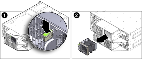
- To remove the faulty fan module, press down on the fan release lever [1].
- While holding the release lever down, use the handle on the fan module to pull it out of the server node [2].
The fan door swings shut to ensure proper cooling.
Install a Fan Module
Note:
Information in this appendix does NOT apply to Oracle Database Appliance X3-2, Oracle Database Appliance X4-2, Oracle Database Appliance X5-2 or Oracle Database Appliance X6 series. Refer to the preceding chapters in this document for information on servicing those systems.This section describes installing a fan module in Oracle Database Appliance Version 1.
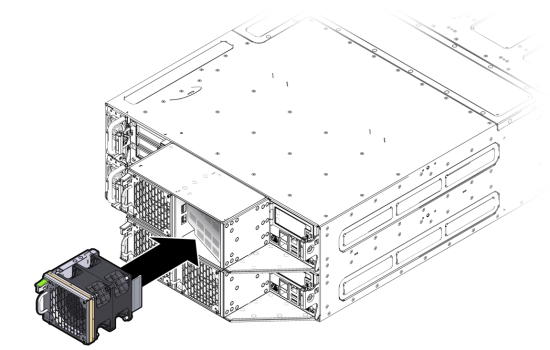
- Align the fan module in the fan door and slide it into the server node.
The extender on the side of the fan module pushes the fan door open, allowing the fan module to enter.
- Apply firm pressure to fully seat the fan module.
The fan release lever engages when the fan is fully seated.
- Verify that the Fan Fault Status LED on the replacement fan module is lit green.
- Verify that the following fault LEDs on the applicable server node are off.
- Front and rear Service Required LEDs located on the applicable server node
- REAR HDD/PS/FAN LED located on the front of the applicable server node
See Server Node Status Indicators for more information about system LEDs.
Servicing Power Supplies (CRU)
Note:
Information in this appendix does NOT apply to Oracle Database Appliance X3-2, Oracle Database Appliance X4-2, Oracle Database Appliance X5-2 or Oracle Database Appliance X6 series. Refer to the preceding chapters in this document for information on servicing those systems.Oracle Database Appliance Version 1 is equipped with two hot pluggable power supplies. They are redundant, meaning that the system can operate with a single power supply. This allows you to remove and replace a power supply without shutting the system down.
If a power supply fails and you do not have a replacement available, to ensure proper airflow, leave the failed power supply installed in the system.
For information about power supply status LEDs, see Power Supply Status Indicators.
This section includes:
Detecting a Power Supply Failure
Note:
Information in this appendix does NOT apply to Oracle Database Appliance X3-2, Oracle Database Appliance X4-2, Oracle Database Appliance X5-2 or Oracle Database Appliance X6 series. Refer to the preceding chapters in this document for information on servicing those systems.The following LEDs light up in Oracle Database Appliance Version 1 when the system detects a power supply fault:
-
Front and rear Service Required LEDs located on each server node
-
REAR HDD/PS/FAN LED located on the front of each server node
-
Service Required LED located on the faulty power supply
See Server Node Status Indicators on page 1-6 for information about these LEDs.
Remove a Power Supply
Note:
Information in this appendix does NOT apply to Oracle Database Appliance X3-2, Oracle Database Appliance X4-2, Oracle Database Appliance X5-2 or Oracle Database Appliance X6 series. Refer to the preceding chapters in this document for information on servicing those systems.This section describes removing a Power Supply from Oracle Database Appliance Version 1.
Caution:
Hazardous voltages. To reduce the risk of electric shock and danger to personal health, follow the instructions.- Identify which power supply (0 or 1) requires replacement.
A lit Service Required LED on a power supply indicates that a failure was detected. For information about power supply status LEDs, see Power Supply Status Indicators.
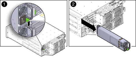
- Disconnect the power cord from the faulty power supply.
- Grasp the power supply handle and press the release latch [1]).
- Pull the power supply out of the chassis [2].
Install a Power Supply
This section describes installing a Power Supply in Oracle Database Appliance Version 1.
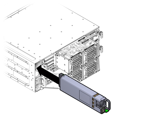
- Align the replacement power supply with the empty power supply chassis bay.
- Slide the power supply into the bay until it is fully seated.
The release latch engages when the power supply is fully seated.
- Reconnect the power cord to the power supply and verify the following:
-
The power supply AC Present LED is lit
-
The power supply Service Required LED is off.
-
- Verify that the following LEDs are off:
-
Service Required LEDs located on the front of both server nodes
-
REAR HDD/PS/FAN LED located on the front of both server nodes
See Storage and Boot Drive Locations for more information about system LEDs.
-
Servicing CRUs That Require Server Node Power Off
This section describes how to service customer-replaceable units (CRUs) for Oracle Database Appliance Version 1. If you have Oracle Database Appliance X6-2 series, go to Servicing Oracle Database Appliance X6-2 Series CRUs. If you have Oracle Database Appliance X3-2, Oracle Database Appliance X4-2, or Oracle Database Appliance X5-2, go to Servicing Oracle Database Appliance X3-2/X4-2/X5-2 CRUs.
This section includes information on how to service the following Oracle Database Appliance Version 1 CRUs:
Server Node CRU Component Locations
Note:
Information in this appendix does NOT apply to Oracle Database Appliance X3-2, Oracle Database Appliance X4-2, Oracle Database Appliance X5-2 or Oracle Database Appliance X6 series. Refer to the preceding chapters in this document for information on servicing those systems.Each server node (also called a system controller) in Oracle Database Appliance Version 1 includes the following replaceable components.
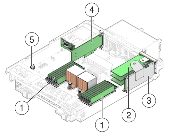
| Callout | Description |
|---|---|
|
1 |
DDR3 Memory DIMMs (12) |
|
2 |
PCIe Cards Mounted on PCIe Riser |
|
3 |
PCIe Riser |
|
4 |
Internal HBA PCIe Card |
|
5 |
Battery |
Servicing Memory Modules (DIMMs) (CRU)
Note:
Information in this appendix does NOT apply to Oracle Database Appliance X3-2, Oracle Database Appliance X4-2, Oracle Database Appliance X5-2 or Oracle Database Appliance X6 series. Refer to the preceding chapters in this document for information on servicing those systems.Each server node in Oracle Database Appliance Version 1 is provisioned with twelve 1333 MHz or 1600 MHz DDR3, 8GB dual rank DIMMs, for a total of 96GB.
The server node supports a maximum memory speed of 1333 MHz, even if 1600 MHz DIMMs are installed.
Before replacing a DIMM see the following:
-
DIMM and CPU physical layout.
For details, see DIMM and CPU Physical Layout.
-
Instructions for removing a faulty DIMM.
For details, see Remove Faulty DIMMs.
-
Instructions for installing a DIMM.
For details, see Install DIMMs.
-
Memory Error Correction and Parity
For details, see Error Correction and Parity Protection.
Caution:
These procedures require you to handle components that are sensitive to static discharge. This sensitivity can cause the component to fail. To avoid damage, ensure that you follow antistatic practices as described in Performing Electrostatic Discharge and Antistatic Prevention Measures.
DIMM and CPU Physical Layout
Note:
Information in this appendix does NOT apply to Oracle Database Appliance X3-2, Oracle Database Appliance X4-2, Oracle Database Appliance X5-2 or Oracle Database Appliance X6 series. Refer to the preceding chapters in this document for information on servicing those systems.Each processor in Oracle Database Appliance Version 1 has six DIMM slots numbered D0 through D5. D0 is the closest to the processor and D5 is the farthest.
Each slot should contain a 1333 MHz or 1600 MHz DDR3, 8GB dual rank DIMM. No other configurations are supported.
The server node supports a maximum memory speed of 1333 MHz, even if it is configured with 1600 MHz DIMMs.
If the system contains a mixture of 1333 MHz and 1600 MHz DIMMs, then P0 and P1 should be configured the same, so that both sides are symmetrical. For example, if you install only two 1600 MHz DIMMs, they should go into P0, D0 and P1, D0.
The following picture shows the physical layout of the DIMMs and CPUs. When viewing the server node from the front, CPU0 (P0) is on the right.
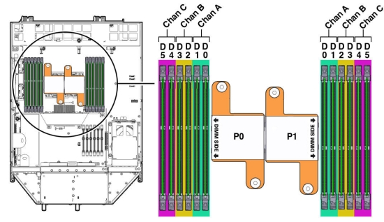
Each processor socket supports three independent memory channels labeled channel A, B, and C, where channel A is closest to the processor socket. Each channel supports two DIMM slots, is controlled by an independent memory controller, and operates independent of the other channels.
Remove Faulty DIMMs
Note:
Information in this appendix does NOT apply to Oracle Database Appliance X3-2, Oracle Database Appliance X4-2, Oracle Database Appliance X5-2 or Oracle Database Appliance X6 series. Refer to the preceding chapters in this document for information on servicing those systems.This section describes removing DIMMs from Oracle Database Appliance Version 1.
Note:
The DDR3 memory modules (DIMMs) are customer-replaceable units (CRUs) and do not require an Oracle-qualified service person for replacement.- Prepare the server node for service.
- Attach an antistatic wrist strap.
See Performing Electrostatic Discharge and Antistatic Prevention Measures.
- Remove the server node from the system.
Power is removed from the server node when you remove it from the system. See Removing Server Nodes From the System Chassis.
- Remove the server node top cover.
- Attach an antistatic wrist strap.
- Identify the faulty DIMM(s).
- To identify the location of a faulty DIMMs, press the Fault Remind button on the motherboard.
Note:
When the Fault Remind button is pressed, the Fault Remind Power Good LED lights green to indicate that there is sufficient voltage present in the fault remind circuit to light the fault LEDs. If this LED fails to light when you press the Fault Remind button, the capacitor powering the fault remind circuit has lost its charge. This can happen if the Fault Remind button is pressed for a long time with fault LEDs lit or if the server node has been out of the chassis for more then 15 minutes.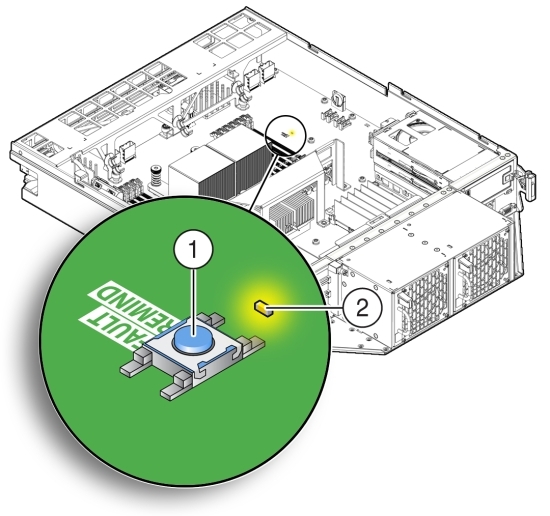
Callout Description 1
Fault Remind Button
2
Fault Remind Power Good LED (green)
- Note the location of faulty DIMMs.
The amber DIMM fault LEDs light if the adjacent DIMM is faulty.
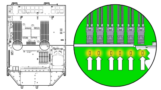
- If the DIMM fault LED is off, the DIMM is operating properly.
- If the DIMM fault Required LED is on (amber), the DIMM is faulty and should be replaced.
- To identify the location of a faulty DIMMs, press the Fault Remind button on the motherboard.
- To remove the faulty DIMM(s), do the following:
- Rotate both DIMM slot ejectors outward as far as they go.
The ejectors push the DIMM partially up.
- Carefully lift the DIMM straight up to remove it from the socket.
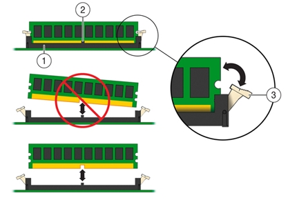
Callout Description 1
DIMM connector slot
2
DIMM connector key
3
DIMM ejector lever
- Rotate both DIMM slot ejectors outward as far as they go.
- Replace each faulty DIMM with either another DIMM of the same rank size.
For DIMM replacement instructions, see Install DIMMs.
Caution:
Do not operate the system with an empty DIMM slot. If you remove a DIMM, you must replace it before starting the server.
Install DIMMs
Note:
Information in this appendix does NOT apply to Oracle Database Appliance X3-2, Oracle Database Appliance X4-2, Oracle Database Appliance X5-2 or Oracle Database Appliance X6 series. Refer to the preceding chapters in this document for information on servicing those systems.This section describes installing DIMMs in Oracle Database Appliance Version 1.
- Unpack the replacement DIMMs and place them on an antistatic mat.
- Ensure that the replacement DIMMs match the system requirements.
The system supports only 1333 MHz or 1600 MHz DDR3, 8GB, dual rank DIMMs obtained from Oracle.
For the best performance, if you combine 1333 MHz and 1600 MHz DIMMs in a single system, they should be configured so that P0 and P1 have the same mixture, in the same DIMM slots. For example, in a 1333 MHz system, if you replace P0, D0 with a 1600 MHz DIMM, you should also replace P1, D0 with a 1600 MHz DIMM.
The server node supports a maximum memory speed of 1333 MHz, even if 1600 MHz DIMMs are installed.
- Ensure that the ejector tabs are in the open position.
- Align the replacement DIMM with the connector.
Align the notch in the DIMM with the key in the connector. The notch ensures that the DIMM is oriented correctly.
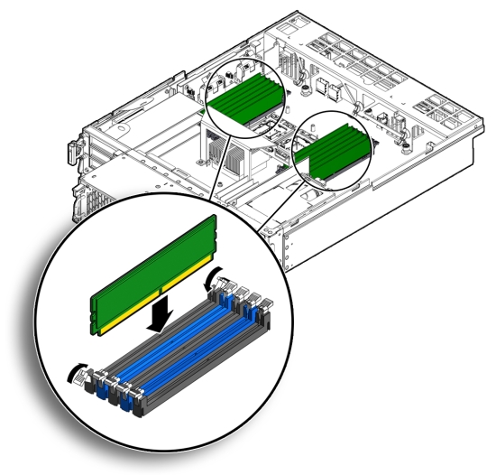
- Push the DIMM into the connector until the ejector tabs lock the DIMM in place.
If the DIMM does not easily seat into the connector, verify that the notch in the DIMM is aligned with the key in the connector as shown above. If the notch is not aligned, damage to the DIMM might occur.
- Repeat Step 3 through Step 5 until all replacement DIMMs are installed.
- Return the server node to operation.
- Install the server node top cover.
- Install the server node into the system.
- Power on the server node.
- Clear the DIMM faults.
- Log in to the server node Oracle ILOM CLI as root.
- To view server node faults, type the following command:
-> show /SP/faultmgmt
Oracle ILOM lists all known faults. For example:
SP/faultmgmt
Targets:
0 (/SYS/MB/P0/D2)
Properties:
Commands:
cd
show
- To clear the DIMM fault, type the following command:
-> set /SYS/MB/Px/Dn clear_fault_action=true
For example, to clear a fault on the DIMM in location D2 on CPU0:
-> set /SYS/MB/P0/D2 clear_fault_action=true
Are you sure you want to clear /SYS/MB/P0 (y/n)? y
Set 'clear_fault_action' to 'true'
Error Correction and Parity Protection
Note:
Information in this appendix does NOT apply to Oracle Database Appliance X3-2, Oracle Database Appliance X4-2, Oracle Database Appliance X5-2 or Oracle Database Appliance X6 series. Refer to the preceding chapters in this document for information on servicing those systems.The Oracle Database Appliance Version 1 server node's processor provides parity protection on its internal cache memories, and error-correcting code (ECC) protection of the data. The server node detects and posts the following errors to the Oracle ILOM event log:
-
Correctable and uncorrectable memory ECC errors
-
Uncorrectable CPU internal errors
Advanced ECC corrects up to 4 bits in error on nibble boundaries, as long as they are all in the same DRAM. If a DRAM fails, the DIMM continues to function.
To clear a fault once the faulty DIMM has been replaced, type the following in the Oracle ILOM CLI:
-> set clear_fault_action=true
For more information on clearing DIMM faults, see the Oracle Integrated Lights Out Manager (Oracle ILOM) 3.0 Documentation Collection: http://www.oracle.com/goto/ILOM/docs.
Servicing PCIe Risers (CRU)
Note:
Information in this appendix does NOT apply to Oracle Database Appliance X3-2, Oracle Database Appliance X4-2, Oracle Database Appliance X5-2 or Oracle Database Appliance X6 series. Refer to the preceding chapters in this document for information on servicing those systems.PCIe cards in Oracle Database Appliance Version 1 are installed on a vertical riser. You must remove the riser to remove and replace a PCIe card. Also, you must remove the PCIe riser when replacing the motherboard.
This section includes:
Caution:
These procedures require that you handle components that are sensitive to static discharge. This sensitivity can cause the component to fail. To avoid damage, ensure that you follow antistatic practices as described inPerforming Electrostatic Discharge and Antistatic Prevention Measures.Remove PCIe Riser From Server Nodes
Note:
Information in this appendix does NOT apply to Oracle Database Appliance X3-2, Oracle Database Appliance X4-2, Oracle Database Appliance X5-2 or Oracle Database Appliance X6 series. Refer to the preceding chapters in this document for information on servicing those systems.This section describes removing a PCIe Riser from Oracle Database Appliance Version 1.
- Prepare the server node for service.
- Attach an antistatic wrist strap.
See Performing Electrostatic Discharge and Antistatic Prevention Measures.
- Remove the server node from the system.
Power is removed from the server node when you remove it from the system. See Removing Server Nodes From the System Chassis.
- Remove the server node top cover.
- Attach an antistatic wrist strap.
- If you are servicing a PCIe card, locate its position on the riser.
- Disconnect any data cables connected to the cards on the PCIe riser being removed.
To disconnect a cable from a PCIe card, press the latch, push in toward the connector, and then pull out to remove the cable.
Note the location of all cables for reinstallation later.
- Ensure that the latch adjacent to the location where PCIe riser is installed is in the open (down) position [1].
If the latch is in the closed position, it prevents you from removing the PCIe riser.
- Loosen the three green captive Phillips screws that secure the PCIe riser to the server node [1].
Access these screws from the rear of the server node.
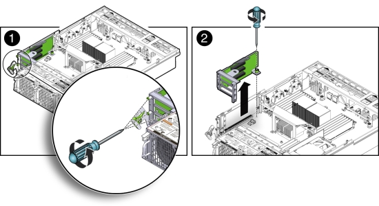
- Loosen the green captive Phillips screw that secures the PCIe riser to the motherboard [2].
- To lift the PCIe riser out of the server node, grasp the front-most side plastic tab with one hand and the rear of the riser with the other hand, and lift it straight up and out of the server node [2].
- Place the PCIe riser and any cards attached to it on an antistatic mat.
Install PCIe Riser in Server Nodes
Note:
Information in this appendix does NOT apply to Oracle Database Appliance X3-2, Oracle Database Appliance X4-2, Oracle Database Appliance X5-2 or Oracle Database Appliance X6 series. Refer to the preceding chapters in this document for information on servicing those systems.This section describes installing a PCIe Riser in Oracle Database Appliance Version 1.
- Before installing the PCIe riser, ensure that the latch adjacent to the location where PCIe riser is to be installed is in the open (down) position [2].
- Install the PCIe riser.
- Ensure that any PCIe cards installed in the PCIe riser are properly seated, and that the card's locking bracket is flush with the recess in the riser and is engaging the locking tab.
For instructions for installing a PCIe card into a PCIe riser, see Install PCIe Card in PCIe Riser.
- Lower the PCIe riser and any cards attached to it, into the server node [1].
- Push the PCIe riser down until its connector is seated into the connector on the motherboard.
- Tighten the green captive Phillips screw that secures the riser to the motherboard [1].
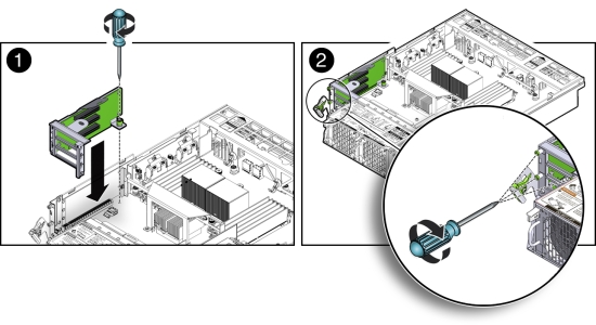
- Tighten the three green captive Phillips screws that secure the PCIe riser to the chassis [2].
Access these screws from the rear of the server node.
- Ensure that any PCIe cards installed in the PCIe riser are properly seated, and that the card's locking bracket is flush with the recess in the riser and is engaging the locking tab.
- Return the server node to operation.
- Install the server node top cover.
- Install the server node into the system.
- Reconnect any data cables to the PCIe card connectors on the system rear panel.
- Power on the server node.
- Clear PCIe riser faults.
- Log in to the Oracle ILOM CLI as root.
- Type:
-> show /SP/faultmgmt
Oracle ILOM lists all known faults. For example:
SP/faultmgmt
Targets:
0 (/SYS/MB/RISER)
Properties:
Commands:
cd
show
- To clear PCIe riser faults, use the set command. For example:
-> set /SYS/MB/RISER clear_fault_action=true
Are you sure you want to clear /SYS/MB/RISER (y/n)? y
Set 'clear_fault_action' to 'true'
Servicing PCIe Cards (CRU)
Note:
Information in this appendix does NOT apply to Oracle Database Appliance X3-2, Oracle Database Appliance X4-2, Oracle Database Appliance X5-2 or Oracle Database Appliance X6 series. Refer to the preceding chapters in this document for information on servicing those systems.This section describes servicing PCIe cards in Oracle Database Appliance Version 1.
PCIe Card Configuration
Note:
Information in this appendix does NOT apply to Oracle Database Appliance X3-2, Oracle Database Appliance X4-2, Oracle Database Appliance X5-2 or Oracle Database Appliance X6 series. Refer to the preceding chapters in this document for information on servicing those systems.The Oracle Database Appliance Version 1 PCIe expansion system includes one standalone low-profile slot on the motherboard and a PCIe riser with three slots. These are provisioned as follows:
-
Motherboard slot – A low-profile, dual-port SAS-2 HBA used internally
-
PCIe slot 2 – Dual-port SAS-2 HBA used internally
-
PCIe slot 1 – Quad-port 1-Gb Ethernet NIC
-
PCIe slot 0 – Dual-port 10-Gb Ethernet NIC
Caution:
If you replace a PCIe card, ensure the replacement is identical to the card you are replacing.Remove PCIe Card From PCIe Riser
Note:
Information in this appendix does NOT apply to Oracle Database Appliance X3-2, Oracle Database Appliance X4-2, Oracle Database Appliance X5-2 or Oracle Database Appliance X6 series. Refer to the preceding chapters in this document for information on servicing those systems.This section describes removing a PCIe card from its riser in Oracle Database Appliance Version 1.
- Prepare the server node for service.
- Attach an antistatic wrist strap.
See Performing Electrostatic Discharge and Antistatic Prevention Measures.
- Remove the server node from the system.
Power is removed from the server node when you remove it from the system. See Removing Server Nodes From the System Chassis.
- Remove the server node top cover.
- Attach an antistatic wrist strap.
- Locate the PCIe card in the PCIe riser that you want to remove.
See the "Oracle Database Appliance Version 1 Back Panel" section of the Oracle Database Owner's Guide for the location of the PCIe slots.
- If necessary, make a note of where the PCIe cards are installed.
- Disconnect all data cables from the PCIe card.
To disconnect a cable from the PCIe card, press the latch, push in toward the connector, and then pull out to remove the cable.
Note the location of all cables for reinstallation later.
- Remove the PCIe riser.
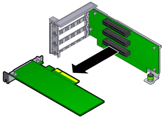
- Remove the PCIe card from the riser.
- Carefully disconnect the PCIe card from the riser connector and remove it from the riser board connector.
- Place the PCIe card on an antistatic mat.
- Carefully disconnect the PCIe card from the riser connector and remove it from the riser board connector.
Install PCIe Card in PCIe Riser
Note:
Information in this appendix does NOT apply to Oracle Database Appliance X3-2, Oracle Database Appliance X4-2, Oracle Database Appliance X5-2 or Oracle Database Appliance X6 series. Refer to the preceding chapters in this document for information on servicing those systems.This section describes installing a PCIe card in a riser in Oracle Database Appliance Version 1.
- Unpack the replacement PCIe card and place it on an antistatic mat.
- Locate the proper PCIe slot for the card you are replacing.
- Remove the PCIe riser.
- Insert the PCIe card into the correct slot on the riser.
- Press the PCIe card until the locking bracket on the PCIe card is flush with the recessed area on the PCIe riser.
- Slide the locking bracket down until it engages the PCIe riser locking tab.
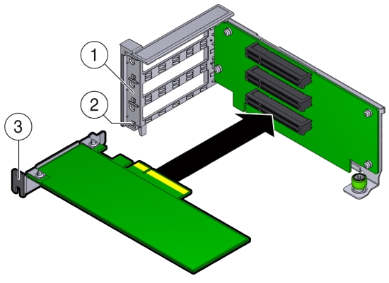
Callout Description 1
Recessed area on the PCIe riser
2
PCIe riser locking tab
3
PCIe card locking bracket
- Install the PCIe riser.
- Reconnect any cables to the PCIe card that you unplugged during the removal procedure.
- Return the server node to operation.
- Install the server node top cover.
- Install the server node into the system.
- Reconnect any data cables to the PCIe card connectors on the system rear panel.
- Power on the server node.
- Clear the PCIe card fault.
- Log in to the server node as root using the Oracle ILOM CLI.
- To view server node faults, type the following command to list all known faults on the system:
-> show /SP/faultmgmt
Oracle ILOM lists all known faults, for example:
SP/faultmgmt
Targets:
0 (/SYS/MB/RISER/PCIE2)
Properties:
Commands:
cd
show
- To clear PCIe riser faults, use the set command. For example:
-> set /SYS/MB/RISER clear_fault_action=true
Are you sure you want to clear /SYS/MB/RISER (y/n)? y
Set 'clear_fault_action' to 'true'
- To clear a PCIe card fault, use the set command. For example, to clear a fault on PCIe 2:
-> set /SYS/MB/RISER/PCIE2 clear_fault_action=true
Are you sure you want to clear /SYS/MB/RISER/PCIE2 (y/n)? y
Set 'clear_fault_action' to 'true'
Remove Primary HBA PCIe Card From Motherboard
Note:
Information in this appendix does NOT apply to Oracle Database Appliance X3-2, Oracle Database Appliance X4-2, Oracle Database Appliance X5-2 or Oracle Database Appliance X6 series. Refer to the preceding chapters in this document for information on servicing those systems.This section describes removing the primary HBA PCIe card from Oracle Database Appliance Version 1.
- Prepare the server node for service.
- Attach an antistatic wrist strap.
See Performing Electrostatic Discharge and Antistatic Prevention Measures.
- Remove the server node from the system.
Power is removed from the server node when you remove it from the system. See Removing Server Nodes From the System Chassis.
- Remove the server node top cover.
- Attach an antistatic wrist strap.
- Remove the primary PCIe card.
- Locate the internal PCIe card [1].
The internal PCIe card is located next to the rear-mounted disk drives.
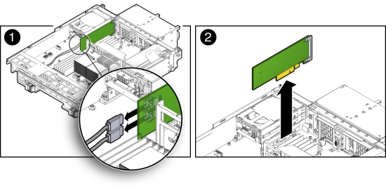
- Disconnect the data cables from the PCIe card [1].
There are two data cables that connect the PCIe card to the server node connector that connects to disk drive backplane.
Note the location of all cables for reinstallation later.
To disconnect the cables from the internal PCIe card, press the latch, push in toward the connector, and then pull out to remove the cable.
- Grasp the PCIe card and lift it up and out of the server node [2].
- Place the PCIe card on an antistatic mat.
- Locate the internal PCIe card [1].
Install Primary HBA PCIe Card in Motherboard
Note:
Information in this appendix does NOT apply to Oracle Database Appliance X3-2, Oracle Database Appliance X4-2, Oracle Database Appliance X5-2 or Oracle Database Appliance X6 series. Refer to the preceding chapters in this document for information on servicing those systems.This section describes installing the primary HBA PCIe card in Oracle Database Appliance Version 1.
- Unpack the replacement PCIe card and place it on an antistatic mat.
- Install the internal PCIe card.
- Locate the connector for the internal PCIe card [1].
The internal PCIe connector is located next to the rear-mounted disk drives.
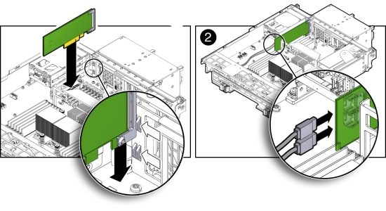
- Align the notch on the PCIe card with the key on the motherboard connector [1].
- Align the rear of the PCIe card with the support bracket located on the rear of the server node [1].
- Press down on the PCIe to seat it into the connector [1].
Caution:
If the notch and key are not aligned, damage to the PCIe card might occur.Note:
To install the primary HBA into the HBA slot on the motherboard, a special PCI metal bracket is required. The standard low-profile metal bracket or full-height metal bracket must be removed from the PCIe card and replaced with the unique metal bracket that is provided with the system. - Reconnect the cables to the PCIe card that you disconnected during the removal procedure [2].
- Locate the connector for the internal PCIe card [1].
- Return the server node to operation.
- Install the server node top cover.
- Install the server node into the system.
- Power on the server node.
- Clear the primary HBA card fault.
- Log in to the server node as root using the Oracle ILOM CLI.
- To view server node faults, type the following command to list all known faults on the server node:
-> show /SP/faultmgmt
Oracle ILOM lists all known faults, for example:
SP/faultmgmt
Targets:
0 (/SYS/MB/HBA)
Properties:
Commands:
cd
show
- To clear the internal PCIe card fault, use the set command. For example:
-> set /SYS/MB/HBA clear_fault_action=true
Are you sure you want to clear /SYS/MB/HBA (y/n)? y
Set 'clear_fault_action' to 'true'
Servicing the Server Node Battery (CRU)
Note:
Information in this appendix does NOT apply to Oracle Database Appliance X3-2, Oracle Database Appliance X4-2, Oracle Database Appliance X5-2 or Oracle Database Appliance X6 series. Refer to the preceding chapters in this document for information on servicing those systems.The Oracle Database Appliance Version 1 battery maintains the date and time for the Oracle ILOM service processor when the server node is removed from the system and, therefore, is powered off. If the server node fails to maintain the proper time when powered off, replace the battery.
Caution:
These procedures require that you handle components that are sensitive to static discharge. This sensitivity can cause the component to fail. To avoid damage, ensure that you follow antistatic practices as described in Performing Electrostatic Discharge and Antistatic Prevention Measures.Remove Battery
Note:
Information in this appendix does NOT apply to Oracle Database Appliance X3-2, Oracle Database Appliance X4-2, Oracle Database Appliance X5-2 or Oracle Database Appliance X6 series. Refer to the preceding chapters in this document for information on servicing those systems.This section describes removing the battery from Oracle Database Appliance Version 1.
- Prepare the server node for service.
- Attach an antistatic wrist strap.
See Performing Electrostatic Discharge and Antistatic Prevention Measures.
- Remove the server node from the system.
Power is removed from the server node when you remove it from the system. See Removing Server Nodes From the System Chassis.
- Remove the server node top cover.
- Attach an antistatic wrist strap.
- Remove the battery.
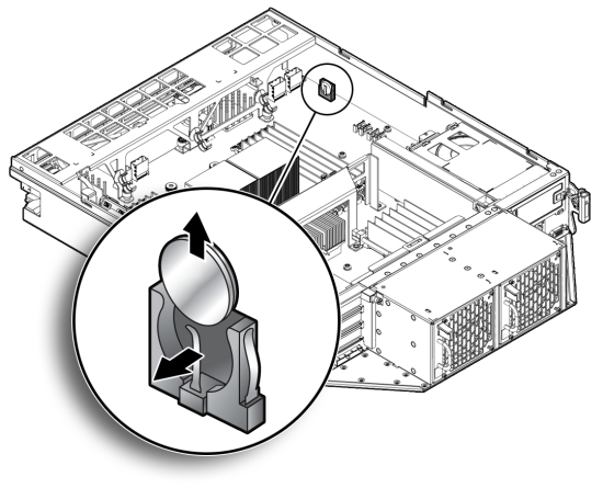
- Place you finger between the battery and the server node side wall and push the battery away from the side wall.
- Twist the battery (either clockwise or counter-clockwise) and lift it out.
Install Battery
Note:
Information in this appendix does NOT apply to Oracle Database Appliance X3-2, Oracle Database Appliance X4-2, Oracle Database Appliance X5-2 or Oracle Database Appliance X6 series. Refer to the preceding chapters in this document for information on servicing those systems.This section describes installing the battery in Oracle Database Appliance Version 1.
- Unpack the replacement battery.
- Press the new battery into the battery holder with the positive side (+) facing the server node side wall.
- If the service processor is configured to synchronize with a network time server using the Network Time Protocol (NTP), the Oracle ILOM clock is reset as soon as the server node is powered on and connected to the network. Otherwise, proceed to the next step.
- If the service processor is not configured to use NTP, you must reset the Oracle ILOM clock using the Oracle ILOM CLI or the web interface.
For instructions, see the Oracle Integrated Lights Out Manager (Oracle ILOM) 3.0 Documentation Collection.
- Return the server node to operation.
- Install the server node top cover.
- Install the server node into the system.
- Power on the server node.
Servicing FRUs
This section describes how to service server node FRUs for Oracle Database Appliance Version 1. If you have Oracle Database Appliance X6-2 series, go to Servicing Oracle Database Appliance X6-2 Series FRUs. If you have Oracle Database Appliance X3-2, Oracle Database Appliance X4-2, or Oracle Database Appliance X5-2, go to Servicing Oracle Database Appliance X3-2/X4-2/X5-2 FRUs.
Note:
Only Oracle authorized service personnel should service FRU components.Removing and Installing the Air Duct (FRU)
Note:
Information in this appendix does NOT apply to Oracle Database Appliance X3-2, Oracle Database Appliance X4-2, Oracle Database Appliance X5-2 or Oracle Database Appliance X6 series. Refer to the preceding chapters in this document for information on servicing those systems.The air duct for the Oracle Database Appliance Version 1 must be removed to service the CPUs.
The air duct is a FRU and can only be replaced by an Oracle-qualified service technician.
Caution:
Equipment overheating. Ensure that the air duct is installed correctly before powering on the server.This section includes the following topics:
Remove Air Duct
Note:
Information in this appendix does NOT apply to Oracle Database Appliance X3-2, Oracle Database Appliance X4-2, Oracle Database Appliance X5-2 or Oracle Database Appliance X6 series. Refer to the preceding chapters in this document for information on servicing those systems.This section describes removing the air duct from Oracle Database Appliance Version 1.
- Prepare the server node for service.
- Attach an antistatic wrist strap.
See Performing Electrostatic Discharge and Antistatic Prevention Measures.
- Remove the server node from the system.
See Removing Server Nodes From the System Chassis.
Power is removed from the server node when you remove it from the system.
- Remove the server node top cover.
- Attach an antistatic wrist strap.
- Remove the air duct.
- From the rear of the server node, grasp the middle/rear of the air duct with your right hand and lift it up to a 45 degree angle [1].
The air duct swings up and away from the rear of the system.
- Grasp the left end of the plastic air duct with your left hand to hold it at a 45 degree angle, and with your right hand press gently down on the middle of the air duct until it bends enough to disengage its left hinge from its socket [2].
- Remove the air duct's right hinge from its socket and set the air duct aside [2].
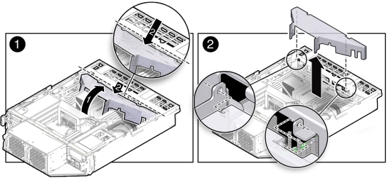
- From the rear of the server node, grasp the middle/rear of the air duct with your right hand and lift it up to a 45 degree angle [1].
Install Air Duct
Note:
Information in this appendix does NOT apply to Oracle Database Appliance X3-2, Oracle Database Appliance X4-2, Oracle Database Appliance X5-2 or Oracle Database Appliance X6 series. Refer to the preceding chapters in this document for information on servicing those systems.This section describes installing the air duct in Oracle Database Appliance Version 1.
Caution:
Equipment overheating. Ensure that the air duct is installed correctly before powering on the server.- Install the air duct into the chassis.
- From the rear of the server node, insert the air duct's right hinge into the right-side socket [2], and place the left hinge on top of the left-side socket.
- Grasp the left end of the air duct with your left hand to hold it at a 45 degree angle, and, with your right hand, press gently down on the middle of the air duct until it bends enough to insert the left hinge into the left-side socket [2].
- Carefully lower the air duct to its closed position, with particular attention given to the SAS cables [1].
Ensure that the openings on each side of the air duct fit around the cables and not on top of them.
Caution:
Equipment overheating. Verify that the air duct is fully closed.
- Return the server node to operation.
- Install the server node top cover.
- Install the server node into the system.
- Power on the server node.
Servicing Processors (CPUs) (FRU)
Note:
Information in this appendix does NOT apply to Oracle Database Appliance X3-2, Oracle Database Appliance X4-2, Oracle Database Appliance X5-2 or Oracle Database Appliance X6 series. Refer to the preceding chapters in this document for information on servicing those systems.This section includes information on servicing CPUs in Oracle Database Appliance Version 1.
The CPU is a FRU and can only be replaced by an Oracle-qualified service technician.
Caution:
Equipment damage. These procedures require that you handle components that are sensitive to static discharge. This sensitivity can cause the component to fail. To avoid damage, ensure that you follow antistatic practices as described in Performing Electrostatic Discharge and Antistatic Prevention Measures.This section includes the following topics:
Remove Processor (CPU)
Note:
Information in this appendix does NOT apply to Oracle Database Appliance X3-2, Oracle Database Appliance X4-2, Oracle Database Appliance X5-2 or Oracle Database Appliance X6 series. Refer to the preceding chapters in this document for information on servicing those systems.This section describes removing a processor from Oracle Database Appliance Version 1.
- Prepare the server node for service.
- Attach an antistatic wrist strap.
See Performing Electrostatic Discharge and Antistatic Prevention Measures.
- Remove the server node from the system.
Power is removed from the server node when you remove it from the system. See Removing Server Nodes From the System Chassis.
- Remove the server node top cover.
- Remove the air duct.
See Remove Air Duct.
- Attach an antistatic wrist strap.
- Remove the CPU.
- Identify which CPU to remove.
- To identify the location of the faulty CPU, press the Fault Remind button on the motherboard.
Note:
When the Fault Remind button is pressed, the Fault Remind Power Good indicator (LED) lights green to indicate that there is sufficient voltage present in the fault remind circuit to light the fault indicators. If this indicator fails to light when you press the Fault Remind button, the capacitor powering the fault remind circuit has lost its charge. This can happen if the Fault Remind button is pressed for a long time with fault indicators lit or if the server node has been out of the chassis for more then 15 minutes. - The fault LED for the faulty CPU lights.
The fault LED is located next to the CPU.
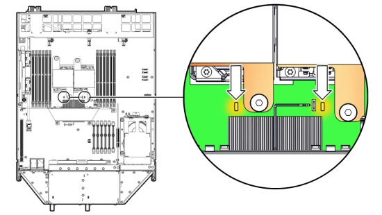
- If CPU fault LED is off: CPU is operating properly.
- If CPU fault LED is on (amber): CPU is faulty and should be replaced.
Viewing the server node from the front, CPU0 (P0) is on the right side of the server node.
- Using a Phillips screwdriver, turn one captive screw on the heatsink counterclockwise two full turns, then turn the other screw two full turns, and keep alternating between the two screws until they are removed [2].
- Twist the heatsink slightly to break the grease seal, then lift it off and place it upside down on a flat surface to prevent the thermal grease from contaminating other components.
- Using the wipes supplied with the replacement CPU, carefully clean the thermal grease from both the bottom of the heatsink and the top of the CPU.
Caution:
Equipment damage. When cleaning the top of the CPU, be careful not to get the thermal grease on the CPU socket and associated components.Caution:
Equipment damage. Failure to clean the heatsink and CPU prior to removing the CPU could result in the accidental contamination of the CPU socket or other components. Also, be careful not to get the grease on your fingers as this could result in contamination of components. - Disengage the CPU release lever by pushing down and moving it to the side away from the CPU, and then rotating the lever upward [3].
- Raise the pressure frame on the CPU to the open position [3].
- Use your index finger to carefully lift up the edge of the CPU or protective cap that is farthest from the socket alignment slots [4], then firmly grasp both sides of the CPU or protective cap with your thumb and index finger on your other hand [4], and carefully lift the CPU or protective cap up and out of the socket [5].
Caution:
Equipment overheating.Whenever you remove a heatsink, you should replace it or install a CPU filler before you return the server to operation; otherwise, the system might overheat due to improper airflow.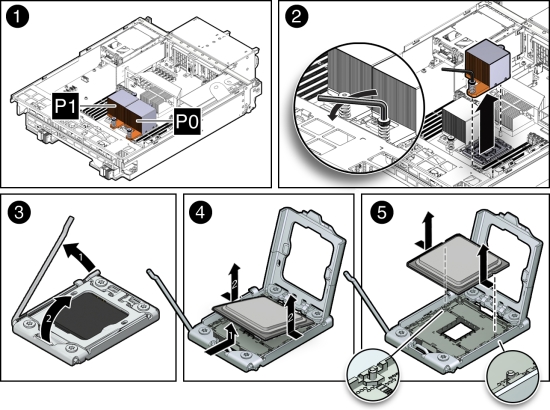
Install Processor (CPU)
Note:
Information in this appendix does NOT apply to Oracle Database Appliance X3-2, Oracle Database Appliance X4-2, Oracle Database Appliance X5-2 or Oracle Database Appliance X6 series. Refer to the preceding chapters in this document for information on servicing those systems.This section describes install a processor in Oracle Database Appliance Version 1.
- Attach an antistatic wrist strap.
See Performing Electrostatic Discharge and Antistatic Prevention Measures.
- Unpack the replacement CPU.
The CPU replacement kit includes a new CPU, wipes, and a tube of thermal grease.
- Install the CPU.
- Grasp the sides of the CPU firmly with your thumb and index finger, tilt it at a 45 degree angle, orient it with the socket alignment tabs [2], carefully lower the end of the CPU with the alignment tabs into the socket [3], support the raised end of the CPU with the index finger on your other hand, and lower the CPU into the socket [3].
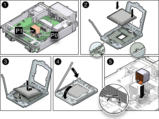
- Lower the pressure frame to the closed position [4].
Ensure that the pressure frame sits flat around the periphery of the CPU.
- Engage the release lever by rotating it downward and slipping it under the catch [4].
- Ensure that there is no debris on the top of the CPU die.
- Use the syringe (supplied with the new or replacement CPU) to apply approximately 0.1 ml of thermal grease to the center of the top of the CPU. Do not distribute the grease.
- Orient the heatsink so that the DIMM SIDE label on the top of the heatsink is facing the memory modules (DIMMs) and the two captive Phillips screws align with the mounting studs.
Each heatsink is labeled to indicate which side of the heatsink faces the memory modules (DIMMs) when the heatsink is properly oriented.
- Tighten the two Phillips screws alternately two full turns at a time until the screws are fully seated [5].
- Grasp the sides of the CPU firmly with your thumb and index finger, tilt it at a 45 degree angle, orient it with the socket alignment tabs [2], carefully lower the end of the CPU with the alignment tabs into the socket [3], support the raised end of the CPU with the index finger on your other hand, and lower the CPU into the socket [3].
- Return the server node to operation.
- Install the air duct.
See Install Air Duct.
- Install the server node top cover.
- Install the server node into the system.
- Power on the server node.
- Install the air duct.
- Clear the CPU faults.
- Log in to the server node as root using the Oracle ILOM CLI.
- To view server node faults, type the following command to list all known faults on the system:
-> show /SP/faultmgmt
Oracle ILOM lists all known faults, for example:
SP/faultmgmt
Targets:
0 (/SYS/MB/P0)
Properties:
Commands:
cd
show
- To clear the fault, type the following command:
-> set /SYS/MB/Pn clear_fault_action=true
For example, to clear a fault on P0:
-> set /SYS/MB/P0 clear_fault_action=true
Are you sure you want to clear /SYS/MB/P0 (y/n)? y
Set 'clear_fault_action' to 'true'
Servicing the Boot Disk Backplane (FRU)
Note:
Information in this appendix does NOT apply to Oracle Database Appliance X3-2, Oracle Database Appliance X4-2, Oracle Database Appliance X5-2 or Oracle Database Appliance X6 series. Refer to the preceding chapters in this document for information on servicing those systems.The Oracle Database Appliance Version 1 boot disk backplane (BDB) serves as an interface between the motherboard and the rear-mounted disk drives.
The boot disk backplane is a FRU and can only be replaced by an Oracle-qualified service technician.
Caution:
Equipment damage. These procedures require that you handle components that are sensitive to static discharge. This sensitivity can cause the component to fail. To avoid damage, ensure that you follow antistatic practices as described in Performing Electrostatic Discharge and Antistatic Prevention Measures.This section includes:
Remove Boot Disk Backplane
Note:
Information in this appendix does NOT apply to Oracle Database Appliance X3-2, Oracle Database Appliance X4-2, Oracle Database Appliance X5-2 or Oracle Database Appliance X6 series. Refer to the preceding chapters in this document for information on servicing those systems.This section describes removing the boot disk backplane from Oracle Database Appliance Version 1.
- Prepare the server node for service.
- Attach an antistatic wrist strap.
See Performing Electrostatic Discharge and Antistatic Prevention Measures.
- Remove the server node from the system.
Power is removed from the server node when you remove it from the system. See Removing Server Nodes From the System Chassis.
- Remove the server node top cover.
- Attach an antistatic wrist strap.
- Unseat the boot disk drives.
See Remove a Boot Drive.
- Remove the boot disk backplane.
- Disconnect the power and data cables [1].
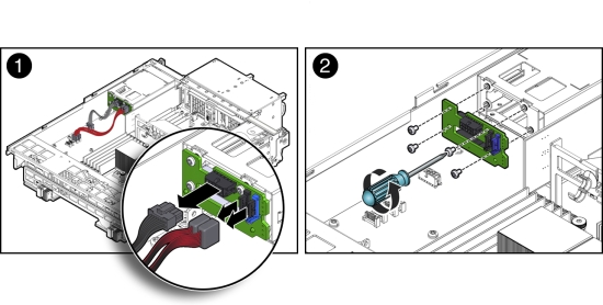
- Remove the four Phillips screws that secure the boot disk backplane to the rear-mounted disk drives assembly and remove the backplane [2].
- Disconnect the power and data cables [1].
- Place the boot disk backplane on an antistatic mat.
Install Boot Disk Backplane
Note:
Information in this appendix does NOT apply to Oracle Database Appliance X3-2, Oracle Database Appliance X4-2, Oracle Database Appliance X5-2 or Oracle Database Appliance X6 series. Refer to the preceding chapters in this document for information on servicing those systems.This section describes installing the boot disk backplane in Oracle Database Appliance Version 1.
- Install the boot disk backplane.
- Position the boot disk backplane on the rear-mounted disk drives assembly and install and tighten the four Phillips screws to secure the backplane [2].
- Reconnect the power cable and the data cables [1].
- Return the server node to operation.
- Re-seat the boot disk drives.
See Install a Boot Drive.
- Install the server node top cover.
- Install the server node into the system.
- Power on the server node.
- Re-seat the boot disk drives.
Servicing the Power Distribution Board (FRU)
Note:
Information in this appendix does NOT apply to Oracle Database Appliance X3-2, Oracle Database Appliance X4-2, Oracle Database Appliance X5-2 or Oracle Database Appliance X6 series. Refer to the preceding chapters in this document for information on servicing those systems.The Oracle Database Appliance Version 1 power distribution board (PDB) distributes power from the power supplies to all system components.
The power distribution board is a FRU and can only be replaced by an Oracle-qualified service technician.
Caution:
Equipment damage. Follow antistatic precautions as described in Performing Electrostatic Discharge and Antistatic Prevention Measures. Do not touch the components along their connector edges.Caution:
Equipment damage. Remove all power from the system before removing or installing the power distribution board. Power down both server nodes (also called system controllers) and disconnect the power cords from the system before performing these procedures. For instructions, see Shutting Down a Server Node and Powering Off the System.This section includes:
Remove Power Distribution Board
Note:
Information in this appendix does NOT apply to Oracle Database Appliance X3-2, Oracle Database Appliance X4-2, Oracle Database Appliance X5-2 or Oracle Database Appliance X6 series. Refer to the preceding chapters in this document for information on servicing those systems.This section describes removing the power distribution board from Oracle Database Appliance Version 1.
- Prepare the system for service.
- Power off the system.
See Shutting Down a Server Node and Powering Off the System.
- Disconnect the power cords from the system.
- If the system is installed in a rack, remove it.
For information on racking the system chassis, see the Oracle Database Appliance Owner's Guide.
- Remove both power supplies from the system.
- Attach an antistatic wrist strap.
See Performing Electrostatic Discharge and Antistatic Prevention Measures.
- Power off the system.
- Remove both server nodes from the system.
- Remove the middle section of the system top cover.
- Remove the power distribution board.
- Disconnect the ribbon cable connector on the power distribution board [1].
The ribbon cable is located between the power distribution board and the chassis side wall. It connects the power distribution board to the disk midplane.
- Remove the two Phillips screws that secure the power distribution board to the chassis [2].
You access the screws through two holes in the side of the chassis.
- Carefully remove the chassis interlock switch connector from the power distribution board [3].
To gain access to the chassis interlock switch connector, grasp the power distribution board with both hands, slide it to the rear of the system chassis to unplug it from the disk midplane module, and lift it up until you can grasp and remove the connector.
- Lift the power distribution board out of the system chassis [4] and place it on the antistatic mat.
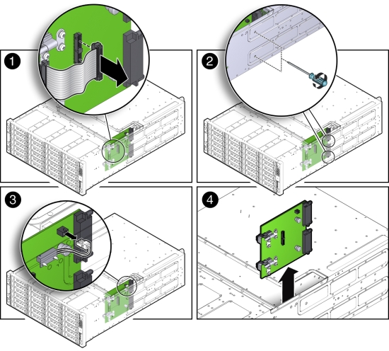
- Disconnect the ribbon cable connector on the power distribution board [1].
Install Power Distribution Board
Note:
Information in this appendix does NOT apply to Oracle Database Appliance X3-2, Oracle Database Appliance X4-2, Oracle Database Appliance X5-2 or Oracle Database Appliance X6 series. Refer to the preceding chapters in this document for information on servicing those systems.This section describes installing the power distribution board in Oracle Database Appliance Version 1.
- Install the power distribution board into the system chassis.
- Lower the power distribution board partially into the system [1].
- Reconnect the chassis interlock switch cable [2].
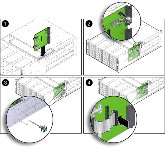
- Align the power distribution board with the two power connectors on the disk midplane module and slide the power distribution board forward until the connectors seat.
- To secure the power distribution board to the system, use the holes in the system side wall to access and tighten the two Phillips screws [3].
- Reconnect the power distribution board ribbon cable [4].
- Return the system to operation.
- Install both server nodes into the system.
- Install the middle section of the top cover.
Install and tighten the Phillips screws that secure the middle section of the top cover to the system chassis.
- Install both power supplies into the system.
- If the system was installed in a rack, reinstall it into the rack.
See the Oracle Database Appliance Owner's Guide for instructions.
- Reconnect the power cords to the system and power on the system.
Servicing the Disk Midplane Module (FRU)
Note:
Information in this appendix does NOT apply to Oracle Database Appliance X3-2, Oracle Database Appliance X4-2, Oracle Database Appliance X5-2 or Oracle Database Appliance X6 series. Refer to the preceding chapters in this document for information on servicing those systems.The Oracle Database Appliance Version 1 disk midplane interconnects the front disk drives to the server nodes, the front indicator modules, and the power distribution board (PDB).
The disk midplane board is a FRU and can only be replaced by an Oracle-qualified service technician.
Caution:
Equipment damage. Follow antistatic precautions as described in Performing Electrostatic Discharge and Antistatic Prevention Measures. Do not touch the components along their connector edges.Caution:
Equipment damage. Remove all power from the system before removing or installing the disk midplane board. Power down both server nodes (also called system controllers) and disconnect the power cords from the system before performing these procedures. For instructions, see Shutting Down a Server Node and Powering Off the System.This section includes:
Remove Disk Midplane Module
Note:
Information in this appendix does NOT apply to Oracle Database Appliance X3-2, Oracle Database Appliance X4-2, Oracle Database Appliance X5-2 or Oracle Database Appliance X6 series. Refer to the preceding chapters in this document for information on servicing those systems.This section describes removing the disk midplane module from Oracle Database Appliance Version 1.
- Prepare the system for service.
- Power off the system.
See Shutting Down a Server Node and Powering Off the System.
- Disconnect the power cords from the system.
- If the system is installed in a rack, remove it.
See the Oracle Database Appliance Owner's Guide for information on racking the system chassis.
- Remove both power supplies from the system.
- Attach an antistatic wrist strap.
See Performing Electrostatic Discharge and Antistatic Prevention Measures.
- Power off the system.
- Remove all of the front storage drives.
- Remove both server nodes from the system.
- Remove the middle section of the system top cover.
- Loosen the two captive Phillips screws that secure the side-wall cover to the chassis and remove the cover.
The side-wall cover is positioned under the middle section of the system top cover. Before you can remove the side-wall cover, you must remove the middle section of the system top cover.
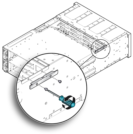
- Remove the power distribution board.
- Remove the disk midplane module.
- Before disconnecting the two front indicator module (FIM) cable connectors from the disk midplane module, label them [1].
The lower connector on the disk midplane is for SN0 and the upper connector is for SN1.
- Disconnect the two FIM cable connectors from the disk midplane module [1].
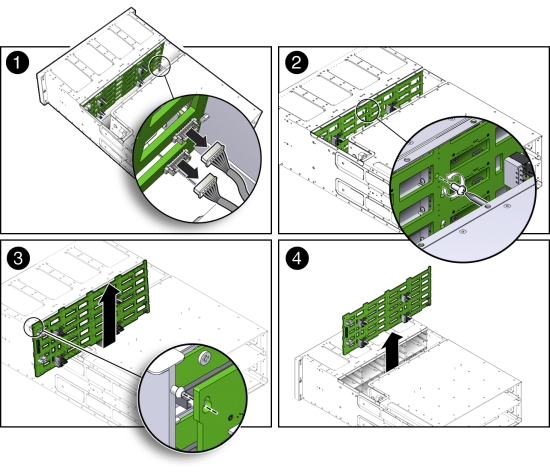
- Remove the Phillips screw that secures the disk midplane module to the disk drive cage [2].
- To remove the disk midplane module from the system chassis, lift the board up about 0.25 inches (6.35 mm) to clear the standoffs that hold it in place [3].
To remove the board, you might need to move the bottom of the board away from the disk drive cage to disengage the standoff located at the top left corner of the board. Then, you should be able to lift the board up and out of the system.
There are four columns of standoffs, four in the left-most column and three in each of the remaining columns.
- Lift the disk midplane module up and out of the system [4].
- Place the board on an antistatic mat.
- Before disconnecting the two front indicator module (FIM) cable connectors from the disk midplane module, label them [1].
Install Disk Midplane Module
Note:
Information in this appendix does NOT apply to Oracle Database Appliance X3-2, Oracle Database Appliance X4-2, Oracle Database Appliance X5-2 or Oracle Database Appliance X6 series. Refer to the preceding chapters in this document for information on servicing those systems.This section describes installing the disk midplane module from Oracle Database Appliance Version 1.
- Install the disk midplane module.
- Move the front indicator module (FIM) cable connectors toward the rear of the system so that the disk midplane module is not installed over them.
- Lower the disk midplane module in the system chassis [1].
- Position the disk midplane module against the disk drive cage, tilting the top slightly forward so that it fits over the top-most standoff on the left side and then position board so that it fits over the remaining 12 standoffs, then push downward on the board to engage the standoffs [2].
- To secure the disk midplane module to the disk drive cage, install the Phillips screw [3].
- Reconnect the two FIM cable connectors to the receptacles on the disk midplane module [4].
Ensure that the FIM connectors are properly connected. The lower connector on the disk midplane is for SN0 and the upper connector is for SN1.
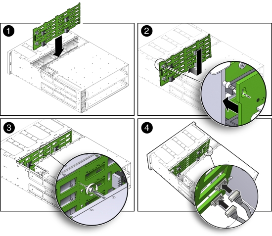
- Install the power distribution board into the system.
- Position the side-wall cover into the chassis and tighten the two captive Phillips screws to secure the side-wall cover to the chassis.
- Install the middle section of the system's top cover.
Install and tighten the Phillips screws that secure the middle section of the top cover to the system chassis.
- Reinstall all of the front storage drives.
- Reinstall both server nodes into the system.
- Return the system to operation.
- Install both power supplies into the system.
- If the system was installed in a rack, reinstall it into the rack.
See the Oracle Database Appliance Owner's Guide for instructions.
- Reconnect the power cords to the system and power on the system.
Servicing the Disk Midplane Module HDD Cable (FRU)
Note:
Information in this appendix does NOT apply to Oracle Database Appliance X3-2, Oracle Database Appliance X4-2, Oracle Database Appliance X5-2 or Oracle Database Appliance X6 series. Refer to the preceding chapters in this document for information on servicing those systems.The Oracle Database Appliance Version 1 HDD cable connects the power distribution board to the disk midplane module.
The disk midplane module HDD cable is a FRU and can only be replaced by an Oracle-qualified service technician.
Caution:
Equipment damage. Remove all power from the system before removing or installing the disk midplane module HDD cable. Power down both server nodes (also called system controllers) and disconnect the power cords from the system before performing these procedures. For instructions, see Shutting Down a Server Node and Powering Off the System.The following topics are covered in this section:
Remove Disk Midplane Module HDD Cable
Note:
Information in this appendix does NOT apply to Oracle Database Appliance X3-2, Oracle Database Appliance X4-2, Oracle Database Appliance X5-2 or Oracle Database Appliance X6 series. Refer to the preceding chapters in this document for information on servicing those systems.This section describes removing the disk midplane module HDD cable from Oracle Database Appliance Version 1.
- Prepare the system for service.
- Power off the system.
See Shutting Down a Server Node and Powering Off the System.
- Disconnect the power cords from the system.
- If the system is installed in a rack, remove it.
See the Oracle Database Appliance Owner's Guide for instructions.
- Attach an antistatic wrist strap.
See Performing Electrostatic Discharge and Antistatic Prevention Measures.
- Power off the system.
- Remove the middle section of the system top cover.
- Disconnect the HDD ribbon cable connector located on the power distribution board [1]).
- Disconnect the HDD ribbon cable connector located on the disk midplane module [2].
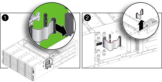
Install Disk Midplane Module HDD Cable
Note:
Information in this appendix does NOT apply to Oracle Database Appliance X3-2, Oracle Database Appliance X4-2, Oracle Database Appliance X5-2 or Oracle Database Appliance X6 series. Refer to the preceding chapters in this document for information on servicing those systems.This section describes installing the disk midplane module HDD cable in Oracle Database Appliance Version 1.
- Reconnect the HDD ribbon cable connector located on the disk midplane module [2]).
- Reconnect the HDD ribbon cable connector located on the power distribution board [1].
- Return the system to operation.
- Install the middle section of the system top cover.
Install and tighten the Phillips screws that secure the middle section of the top cover to the system chassis.
- If the system was installed in a rack, reinstall it into the rack.
See the Oracle Database Appliance Owner's Guide for instructions.
- Reconnect the power cords to the system and power on the system.
- Install the middle section of the system top cover.
Servicing the Front Indicator Panels (FRU)
Note:
Information in this appendix does NOT apply to Oracle Database Appliance X3-2, Oracle Database Appliance X4-2, Oracle Database Appliance X5-2 or Oracle Database Appliance X6 series. Refer to the preceding chapters in this document for information on servicing those systems.The Oracle Database Appliance Version 1 front indicator panels contain the LEDs and indicators on the front of the system. Each server node has its own front indicator panel, which sits behind the ears on the system chassis.
The front indicator panels are FRUs and can only be replaced by an Oracle-qualified service technician.
Caution:
Equipment damage. Remove all power from the system before removing or installing the front indicator panels. Power down both server nodes (also called system controllers) and disconnect the power cords from the system before performing these procedures. For instructions, see Shutting Down a Server Node and Powering Off the System.The following topics are covered in this section:
Remove Front Indicator Panel
Note:
Information in this appendix does NOT apply to Oracle Database Appliance X3-2, Oracle Database Appliance X4-2, Oracle Database Appliance X5-2 or Oracle Database Appliance X6 series. Refer to the preceding chapters in this document for information on servicing those systems.This section describes removing the front indicator panel from Oracle Database Appliance Version 1.
- Prepare the system for service.
- Power off the system (both server nodes).
See Shutting Down a Server Node and Powering Off the System.
- Disconnect the power cords from the system.
- If the system is installed in a rack, remove it.
See the Oracle Database Appliance Owner's Guide for information on racking the system chassis.
- Attach an antistatic wrist strap.
See Performing Electrostatic Discharge and Antistatic Prevention Measures.
- Power off the system (both server nodes).
- Remove the adjacent disk drives [1].
Be sure to mark them so that you can return them to the correct drive bays later.
- Unscrew the three Phillips screws from the back of the ear bezel [2].
- Remove four more Phillips screws from the inside of the drive bays [3].
- Remove the ear bezel [4].
The ear bezel and indicator panels remain connected to the ribbon cables.
- Disconnect the ribbon cables from the indicator panel you wish to change [5].
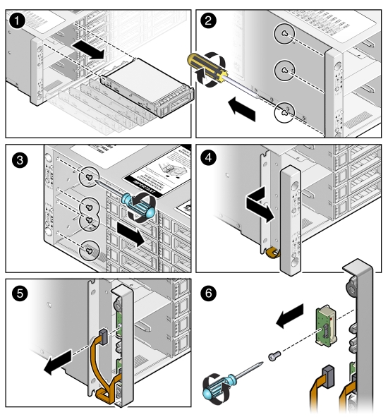
- Remove the screw that holds the indicator panel to the ear bezel [6].
Make sure you remove the correct indicator panel. There are two indicator panels on the ear bezel.
Install Front Indicator Panel
Note:
Information in this appendix does NOT apply to Oracle Database Appliance X3-2, Oracle Database Appliance X4-2, Oracle Database Appliance X5-2 or Oracle Database Appliance X6 series. Refer to the preceding chapters in this document for information on servicing those systems.This section describes installing the front indicator panel in Oracle Database Appliance Version 1.
- Use the Phillips screw to attach the new indicator panel to the ear bezel [1].
- Connect the ribbon cable to the indicator panel [2].
- Place the ear bezel on the chassis [3].
- Fasten the four Phillips screws inside the drive bays [4].
- Fasten the three Phillips screws on the back of the ear bezel [5].
- Replace the disk drives in the drive bays [6].
Use the marks to ensure that you return each drive to its original bay.
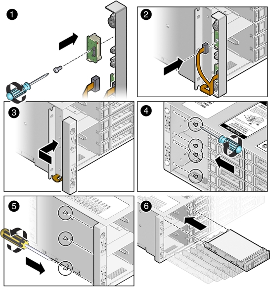
- Return the system to operation.
- Reinstall the system into the rack.
See the Oracle Database Appliance Owner's Guide for instructions.
- Reconnect the power cords to the system and power on the system.
- Reinstall the system into the rack.
Servicing Server Node Cables
Note:
Information in this appendix does NOT apply to Oracle Database Appliance X3-2, Oracle Database Appliance X4-2, Oracle Database Appliance X5-2 or Oracle Database Appliance X6 series. Refer to the preceding chapters in this document for information on servicing those systems.This section includes information on servicing cables in Oracle Database Appliance Version 1.
The internal server node cables are FRUs and can only be replaced by an Oracle-qualified service technician.
Caution:
Equipment damage. These procedures require that you handle components that are sensitive to static discharge. This sensitivity can cause the component to fail. To avoid damage, ensure that you follow antistatic practices as described in Performing Electrostatic Discharge and Antistatic Prevention Measures.The following topics are covered in this section:
Servicing the Fan Power Cables (FRU)
Each Oracle Database Appliance Version 1 server node has two fans and each fan has a separate power cable.
Remove Fan Power Cables
Note:
Information in this appendix does NOT apply to Oracle Database Appliance X3-2, Oracle Database Appliance X4-2, Oracle Database Appliance X5-2 or Oracle Database Appliance X6 series. Refer to the preceding chapters in this document for information on servicing those systems.This section describes removing the fan power cables from Oracle Database Appliance Version 1.
- Prepare the server node for service.
- Attach an antistatic wrist strap.
See Performing Electrostatic Discharge and Antistatic Prevention Measures.
- Remove the server node from the system.
Power is removed from the server node when you remove it from the system. See Removing Server Nodes From the System Chassis.
- Remove the server node top cover.
- Attach an antistatic wrist strap.
- Disconnect the fan power cables and remove them from the server node.
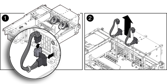
Install Fan Power Cables
Note:
Information in this appendix does NOT apply to Oracle Database Appliance X3-2, Oracle Database Appliance X4-2, Oracle Database Appliance X5-2 or Oracle Database Appliance X6 series. Refer to the preceding chapters in this document for information on servicing those systems.This section describes installing the fan power cables in Oracle Database Appliance Version 1.
- Reconnect the fan power cables.
- Return the server node to operation.
- Install the server node top cover.
- Install the server node into the system.
- Power on the server node.
Servicing the PCIe Card Cables (FRU)
The Oracle Database Appliance Version 1 PCIe card cables are used to connect the internal PCIe card, the primary HBA and a riser-mounted PCIe card, and the secondary HBA to the motherboard. See the following sections for instructions.
The PCIe card cables are FRUs and can only be replaced by an Oracle-qualified service technician.
Remove PCIe Card Cables From Primary HBA PCIe Card
Note:
Information in this appendix does NOT apply to Oracle Database Appliance X3-2, Oracle Database Appliance X4-2, Oracle Database Appliance X5-2 or Oracle Database Appliance X6 series. Refer to the preceding chapters in this document for information on servicing those systems.This section describes removing PCIe card cables from Oracle Database Appliance Version 1.
- Prepare the server node for service.
- Attach an antistatic wrist strap.
See Performing Electrostatic Discharge and Antistatic Prevention Measures.
- Remove the server node from the system.
Power is removed from the server node when you remove it from the system. See Removing Server Nodes From the System Chassis.
- Remove the server node top cover.
- Attach an antistatic wrist strap.
- Disconnect the primary HBA PCIe card cables and remove them from the server node.
- Loosen the three green, captive Phillips screws that secure the server node's front cover and remove the cover [1].
- Disconnect the two cables from the primary HBA PCIe card and remove the cables [2].
To remove each cable connector, push the connector inward, press down on the connector to release it, and pull the connector out.
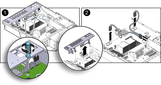
Install PCIe Card Cables for Primary HBA PCIe Card
Note:
Information in this appendix does NOT apply to Oracle Database Appliance X3-2, Oracle Database Appliance X4-2, Oracle Database Appliance X5-2 or Oracle Database Appliance X6 series. Refer to the preceding chapters in this document for information on servicing those systems.This section describes installing PCIe card cables in Oracle Database Appliance Version 1.
- Reconnect the PCIe card cables.
- Reconnect the two PCIe card cables to the primary HBA PCIe card and the connectors on the motherboard [2].
Notice that there are two sets of connectors on the motherboard. Be sure to connect the cables to the connector on the right in each set (looking at the connectors from the rear of the server node).
- Position the server node's front cover onto the server node and tighten the three green, captive Phillips screws that secure the server node's front cover to the motherboard [1].
- Reconnect the two PCIe card cables to the primary HBA PCIe card and the connectors on the motherboard [2].
- Return the server node to operation.
- Install the server node top cover.
- Install the server node into the system.
- Power on the server node.
Remove PCIe Card Cables From Secondary HBA PCIe Card
Note:
Information in this appendix does NOT apply to Oracle Database Appliance X3-2, Oracle Database Appliance X4-2, Oracle Database Appliance X5-2 or Oracle Database Appliance X6 series. Refer to the preceding chapters in this document for information on servicing those systems.This section describes removing secondary HBA PCIe card cables from Oracle Database Appliance Version 1.
- Prepare the server node for service.
- Attach an antistatic wrist strap.
See Performing Electrostatic Discharge and Antistatic Prevention Measures.
- Remove the server node from the system.
Power is removed from the server node when you remove it from the system. See Removing Server Nodes From the System Chassis.
- Remove the server node top cover.
- Attach an antistatic wrist strap.
- Disconnect the PCIe card cables and remove them from the server node.
The Secondary HBA PCIe Card sits in the top slot on the PCIe riser (PCIe slot 2)
- Loosen the three green, captive Phillips screws that secure the server node's front cover and remove the cover [1].
- Disconnect the two secondary HBA PCIe card cables and remove the cables [2].
To remove each cable connector, push the connector inward, press down on the connector to release it, and pull the connector out.
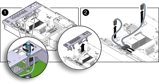
Install PCIe Card Cables for Secondary HBA PCIe Card
Note:
Information in this appendix does NOT apply to Oracle Database Appliance X3-2, Oracle Database Appliance X4-2, Oracle Database Appliance X5-2 or Oracle Database Appliance X6 series. Refer to the preceding chapters in this document for information on servicing those systems.This section describes installing secondary HBA PCIe card cables in Oracle Database Appliance Version 1.
- Reconnect the PCIe card cables.
- Reconnect the two PCIe card cables between to the secondary PCIe card and the connectors on the motherboard [2].
The Secondary HBA PCIe Card sits in the top slot on the PCIe riser (PCIe slot 2)
Notice that there are two sets of connectors on the motherboard. Be sure to connect the cables to connector on the left in each set (looking at the connectors from the rear of the server node).
- Position the server node's front cover onto the server node and tighten the three green, captive Phillips screws that secure the server node's front cover to the motherboard [1].
- Reconnect the two PCIe card cables between to the secondary PCIe card and the connectors on the motherboard [2].
- Return the server node to operation.
- Install the server node top cover.
- Install the server node into the system.
- Power on the server node.
Servicing the SAS Expander Cable (FRU)
Note:
Information in this appendix does NOT apply to Oracle Database Appliance X3-2, Oracle Database Appliance X4-2, Oracle Database Appliance X5-2 or Oracle Database Appliance X6 series. Refer to the preceding chapters in this document for information on servicing those systems.The Oracle Database Appliance Version 1 SAS expander cable runs from a connector on the front of the motherboard to a connector near the rear of the motherboard. See the following sections for instructions.
The SAS expander cable is a FRU and can only be replaced by an Oracle-qualified service technician.
The following topics are covered in this section:
Remove SAS Expander Cable
Note:
Information in this appendix does NOT apply to Oracle Database Appliance X3-2, Oracle Database Appliance X4-2, Oracle Database Appliance X5-2 or Oracle Database Appliance X6 series. Refer to the preceding chapters in this document for information on servicing those systems.This section describes removing the SAS expander cable from Oracle Database Appliance Version 1.
- Prepare the server node for service.
- Attach an antistatic wrist strap.
See Performing Electrostatic Discharge and Antistatic Prevention Measures.
- Remove the server node from the system.
Power is removed from the server node when you remove it from the system. See Removing Server Nodes From the System Chassis.
- Remove the server node top cover.
- Remove the PCIe riser.
- Attach an antistatic wrist strap.
- Disconnect the SAS expander cable and remove it from the server node.
- Loosen the three green, captive Phillips screws that secure the server node's front cover and remove the cover [1].
- Disconnect both cable connectors from the motherboard and remove the cable [2].
Push the connector inward, press down on the connector to release it, and pull the connector out.
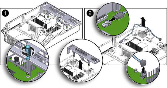
Install SAS Expander Cable
Note:
Information in this appendix does NOT apply to Oracle Database Appliance X3-2, Oracle Database Appliance X4-2, Oracle Database Appliance X5-2 or Oracle Database Appliance X6 series. Refer to the preceding chapters in this document for information on servicing those systems.This section describes installing the SAS expander cable in Oracle Database Appliance Version 1.
- Reconnect the SAS expander cable.
- Reconnect the SAS expander cable connectors to the motherboard [2].
- Position the server node's front cover onto the server node and tighten the three green, captive Phillips screws that secure the server node's front cover to the motherboard [1].
- Return the server node to operation.
- Install the PCIe riser.
- Install the server node top cover.
- Install the server node into the system.
- Power on the server node.
Servicing the Boot Disk Backplane Cables (FRU)
Note:
Information in this appendix does NOT apply to Oracle Database Appliance X3-2, Oracle Database Appliance X4-2, Oracle Database Appliance X5-2 or Oracle Database Appliance X6 series. Refer to the preceding chapters in this document for information on servicing those systems.The Oracle Database Appliance Version 1 boot disk backplane cables connect the boot disk backplane to the motherboard.
The boot disk backplane cables are FRUs and can only be replaced by an Oracle-qualified service technician.
The following topics are covered in this section:
Remove Boot Disk Backplane Cables
Note:
Information in this appendix does NOT apply to Oracle Database Appliance X3-2, Oracle Database Appliance X4-2, Oracle Database Appliance X5-2 or Oracle Database Appliance X6 series. Refer to the preceding chapters in this document for information on servicing those systems.This section describes removing the boot disk backplane cables from Oracle Database Appliance Version 1.
- Prepare the server node for service.
- Attach an antistatic wrist strap.
See Performing Electrostatic Discharge and Antistatic Prevention Measures.
- Remove the server node from the system.
Power is removed from the server node when you remove it from the system. See Removing Server Nodes From the System Chassis.
- Remove the server node top cover.
- Attach an antistatic wrist strap.
- Disconnect the power cable and hard disk drive (HDD) cables and remove them from the server node.
- Disconnect the power cable and HDD cables from the motherboard [1].
- Disconnect the power cable and HDD cables from the boot disk backplane [2].
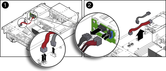
Install Boot Disk Backplane Cables
Note:
Information in this appendix does NOT apply to Oracle Database Appliance X3-2, Oracle Database Appliance X4-2, Oracle Database Appliance X5-2 or Oracle Database Appliance X6 series. Refer to the preceding chapters in this document for information on servicing those systems.This section describes installing the boot disk backplane cables in Oracle Database Appliance Version 1.
- Reconnect the power cable and hard disk drive (HDD) cables.
- Reconnect the power cable and HDD cables to the boot disk backplane [2].
- Reconnect the power cable and HDD cables to the motherboard [1].
- Return the server node to operation.
- Install the server node top cover.
- Install the server node into the system.
- Power on the server node.
Servicing the Motherboard Assembly (FRU)
Note:
Information in this appendix does NOT apply to Oracle Database Appliance X3-2, Oracle Database Appliance X4-2, Oracle Database Appliance X5-2 or Oracle Database Appliance X6 series. Refer to the preceding chapters in this document for information on servicing those systems.Each Oracle Database Appliance Version 1 server node has a motherboard assembly. The service strategy for the motherboard is to remove the replaceable components from the server node and then return the server node with the motherboard in place to Oracle for repair or replacement.
The motherboard assembly is a FRU and can only be replaced by an Oracle-qualified service technician.
Caution:
Equipment damage. These procedures require that you handle components that are sensitive to static discharge. This sensitivity can cause the component to fail. To avoid damage, ensure that you follow antistatic practices as described in Performing Electrostatic Discharge and Antistatic Prevention Measures.The following figure shows the components that must be removed from the server node.
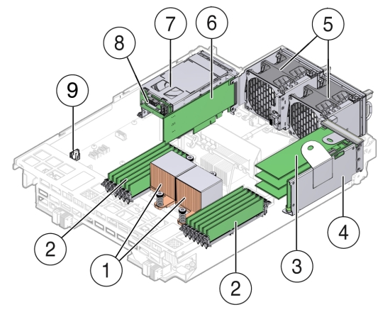
| Callout | Description |
|---|---|
|
1 |
CPUs and Heatsinks |
|
2 |
Memory modules (DIMMs) |
|
3 |
PCIe Cards mounted on the PCIe Riser |
|
4 |
PCIe Riser |
|
5 |
Fan Modules (2) |
|
6 |
Internally Mounted PCIe Card |
|
7 |
Boot Disk Drives (2) |
|
8 |
Boot Disk Drive Backplane |
|
9 |
Battery |
The following topics are covered in this section:
Remove Replaceable Components From Motherboard Assembly
Note:
Information in this appendix does NOT apply to Oracle Database Appliance X3-2, Oracle Database Appliance X4-2, Oracle Database Appliance X5-2 or Oracle Database Appliance X6 series. Refer to the preceding chapters in this document for information on servicing those systems.This section describes removing the replaceable components prior to removing the motherboard from Oracle Database Appliance Version 1.
- Prepare the server node for service.
- Attach an antistatic wrist strap.
See Performing Electrostatic Discharge and Antistatic Prevention Measures.
- Remove the server node from the system.
Power is removed from the server node when you remove it from the system. See Removing Server Nodes From the System Chassis.
- Remove the server node top cover.
- Attach an antistatic wrist strap.
- With the exception the SAS expander cable, disconnect and remove all internal cables from the server node.
Note:
To identify the SAS expander cable, see Install SAS Expander Cable.The cables for the fans, the primary and secondary HBA PCIe cards, and the boot disk backplane must be removed.
-
Fan power cables
See Remove Remove Fan Power Cables.
-
Primary HBA PCIe card data cables
-
Secondary HBA PCIe card data cables
See Remove PCIe Card Cables From Secondary HBA PCIe Card.
Caution:
Equipment damage. The HBA data cables are delicate. Ensure that they are removed and safely out of the way when servicing the motherboard. -
Boot disk board cables.
-
- Remove the following components from the server node.
-
Fan modules
-
Boot disk drives
-
Boot disk drive backplane
-
Memory modules (DIMMS)
-
PCIe riser and attached PCIe cards
-
CPUs
-
Internal primary HBA PCIe card
-
Battery
-
Install Replaceable Components in Motherboard Assembly
Note:
Information in this appendix does NOT apply to Oracle Database Appliance X3-2, Oracle Database Appliance X4-2, Oracle Database Appliance X5-2 or Oracle Database Appliance X6 series. Refer to the preceding chapters in this document for information on servicing those systems.This section describes reinstalling the replaceable components removed when replacing the motherboard in Oracle Database Appliance Version 1.
- Attach an antistatic wrist strap.
See Performing Electrostatic Discharge and Antistatic Prevention Measures.
- Install the following components into the server node.
-
Fan modules
See Install a Fan Module.
-
Boot disk drives
See Install a Boot Drive.
-
Memory modules (DIMMS)
See Install DIMMs.
-
PCIe riser and attached PCIe cards
-
CPUs
-
Internal primary HBA PCIe card
-
- Reconnect and install the following cables.
-
Fan module power cables.
-
Internal PCIe card data cables.
See Servicing the PCIe Card Cables (FRU).
Caution:
Equipment damage. The disk drive data cables are delicate. Handle them carefully. -
Boot disk backplane cables.
-
- Return the server node to operation.
- Install the server node top cover.
- Install the server node into the system.
- Reconnect all external data cables from the PCIe card(s) that are installed in the PCIe riser.
- Power on the server node.
Returning the Appliance to Operation
This section describes returning Oracle Database Appliance Version 1 to operation after servicing. If you have Oracle Database Appliance X6-2 series, go to Returning Oracle Database Appliance X6-2 Series to Operation. If you have Oracle Database Appliance X3-2, Oracle Database Appliance X4-2, or Oracle Database Appliance X5-2, go to Returning Oracle Database Appliance X3-2/X4-2/X5-2 to Operation.
Installing the Server Node Top Cover
Note:
Information in this appendix does NOT apply to Oracle Database Appliance X3-2, Oracle Database Appliance X4-2, Oracle Database Appliance X5-2 or Oracle Database Appliance X6 series. Refer to the preceding chapters in this document for information on servicing those systems.If you removed the top cover from an Oracle Database Appliance Version 1 server node, perform the following procedure to replace it.
Caution:
Hazardous voltage present. Do not run the system with the top cover removed.Caution:
Equipment damage. Install the top cover properly before starting the system.Install Server Node Top Cover
Note:
Information in this appendix does NOT apply to Oracle Database Appliance X3-2, Oracle Database Appliance X4-2, Oracle Database Appliance X5-2 or Oracle Database Appliance X6 series. Refer to the preceding chapters in this document for information on servicing those systems.This section describes installing the server node top cover for Oracle Database Appliance Version 1.
- Place the top cover down on the server node so that it hangs over the front of the chassis by 0.5 inches (12.7 mm).
- Ensure that all six of the standoffs on the underside of the cover (three on each side) fit into the slots on the top of the chassis side walls.
When the top cover is positioned (as described in previous step), the six standoffs on the underside of the cover fit into the slots in the top of the chassis sidewalls.
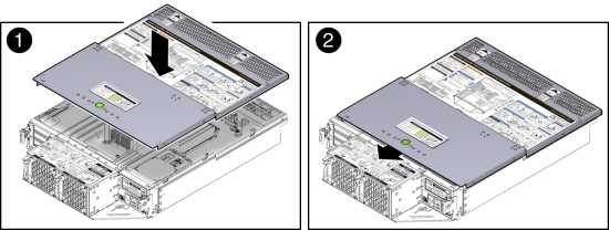
- Slide the top cover toward the rear of the server node until it seats [2].
Installing a Server Node Into the System Chassis
If you removed a Oracle Database Appliance Version 1 server node from the chassis, perform the following procedure to reinstall it.
Install Server Node Into System Chassis
Note:
Information in this appendix does NOT apply to Oracle Database Appliance X3-2, Oracle Database Appliance X4-2, Oracle Database Appliance X5-2 or Oracle Database Appliance X6 series. Refer to the preceding chapters in this document for information on servicing those systems.This section describes installing a server node into the system chassis for Oracle Database Appliance Version 1.
Note:
Replacing a server node FRU with a new server node is a service activity that must be performed by an Oracle-qualified service technician. The customer may remove the server node to service other customer serviceable components in the server node.- Before inserting the server node into the system chassis, ensure that both release latches on the rear of the server node are in the open position.
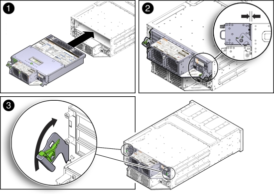
- Slide the server node into the rear of the system chassis until the bottom lips of the release latches touch the chassis [2].
- To re-seat the server node in the system chassis, grasp both release latches, one on each side of the server node, and push them upward simultaneously to the closed position [3].
Caution:
Equipment damage. Always use the release latches to re-seat the server node into the system chassis as described in this procedure. Failure to do so might damage the connectors on the front of the server node and/or the connectors on the disk midplane module. - Reinstall the system chassis into the rack.
Follow the instructions listed in the "Inserting Oracle Database Appliance Version 1 Into a Rack" section in the Oracle Database Appliance Owner's Guide.
Powering On Oracle Database Appliance Version 1
Note:
Information in this appendix does NOT apply to Oracle Database Appliance X3-2, Oracle Database Appliance X4-2, Oracle Database Appliance X5-2 or Oracle Database Appliance X6 series. Refer to the preceding chapters in this document for information on servicing those systems.To power on Oracle Database Appliance Version 1, follow this procedure.
Each server node is powered on separately.
Note:
To use Oracle ILOM to power on a server node, ensure that you have performed its initial configuration as described in "Connecting and Configuring Oracle ILOM" in the Oracle Database Appliance Getting Started Guide.Power On Oracle Database Appliance Version 1
Note:
Information in this appendix does NOT apply to Oracle Database Appliance X3-2, Oracle Database Appliance X4-2, Oracle Database Appliance X5-2 or Oracle Database Appliance X6 series. Refer to the preceding chapters in this document for information on servicing those systems.This section describes powering on Oracle Database Appliance Version 1.
- Ensure that the power cord (or cords) are connected to the power supplies on the rear of the server node that was serviced.
Once plugged in, the server node goes into the standby power state. The SP status LED on the front panel of the server node lights green and goes from slow blink to steady on. The Power/OK LED on the front panel of the server node lights green and goes to standby blink. It might take about five minutes for the LED to reach standby blink after the power cord is inserted.
For the location of the SP status LED and Power/OK LED, see Server Node Status Indicators.
Standby power state indicates that the server node's service processor is active, but the server node host is powered off.
- Power on a server node by performing one of the following:
If you powered off a single server node without shutting down the appliance, perform this step only for that server node. If you shut down the appliance completely, then perform this step for both server nodes.
- Using the server node's Power button: Momentarily press and release the recessed Power button on the front panel [1].

On the server node, the green Power/OK LED [2] blinks while the server node is booting, and remains steady on when the server node is operational.
- Using the Oracle ILOM web interface:
- Open a browser and enter the server node's service processor IP address in the browser's address field.
- At the log in page, type a user name (the account must have Reset and Host Control (r) privileges) and password, and click the Log In button.
- Go to Remote Power Control and select Power On from the Select Action list box and then click Save and OK.
On the server node, the green Power/OK LED [2] blinks while the server node is booting, and remains steady on when the server node is operational.
- Using the Oracle ILOM CLI:
- Log in to Oracle ILOM using an ssh client. Type:
$ssh username@sp_ip_address
Where username is a user account name with Reset and Host Control (r) privileges and sp_ip_address is the IP address of the server node service processor.
- When prompted, enter the user account password.
- Enter the command to power on the server node:
-> start /SYS
On the server node, the green Power/OK LED [2] blinks while the server node is booting, and remains steady on when the server node is operational.
- Log in to Oracle ILOM using an ssh client. Type:
- Using the server node's Power button: Momentarily press and release the recessed Power button on the front panel [1].
Server Node Basic Input/Output System (BIOS)
Note:
Information in this appendix does NOT apply to Oracle Database Appliance X3-2, Oracle Database Appliance X4-2, Oracle Database Appliance X5-2 or Oracle Database Appliance X6 series. Refer to the preceding chapters in this document for information on servicing those systems.This section describes the Oracle Database Appliance Version 1 BIOS utility. If you have Oracle Database Appliance X6-2 series, go to Oracle Database Appliance X6-2 Series BIOS Utility. If you have Oracle Database Appliance X3-2, Oracle Database Appliance X4-2, or Oracle Database Appliance X5-2, go to Oracle Database Appliance X3-2/X4-2/X5-2 BIOS Utility.
This section describes the Oracle Database Appliance Version 1 BIOS utility.
All settings are set to the optimal defaults at startup.
Caution:
You should not configure system BIOS settings. Oracle Database Appliance patch software will do this for you. The only time you might need to configure BIOS settings would be if requested to do so by Oracle Service.The following topics are included:
BIOS Booting and Setup
Note:
Information in this appendix does NOT apply to Oracle Database Appliance X3-2, Oracle Database Appliance X4-2, Oracle Database Appliance X5-2 or Oracle Database Appliance X6 series. Refer to the preceding chapters in this document for information on servicing those systems.The following sections describe the tests performed by BIOS during Oracle Database Appliance Version 1 bootup:
Default BIOS Power-On Self-Test (POST) Events
Note:
Information in this appendix does NOT apply to Oracle Database Appliance X3-2, Oracle Database Appliance X4-2, Oracle Database Appliance X5-2 or Oracle Database Appliance X6 series. Refer to the preceding chapters in this document for information on servicing those systems.When an Oracle Database Appliance Version 1 server node (also called a system controller) starts, the BIOS performs a power-on self-test that checks the hardware to ensure that all components are present and functioning properly. The following table identifies the events that can occur during BIOS POST, as well as specifies whether these events can prevent the host from powering-on.
| Event | Cause | Boot Continues on Host? |
|---|---|---|
|
User password violation |
Attempt to enter password fails three times |
No |
|
Setup password violation |
Attempt to enter password fails three times |
No |
|
Correctable ECC |
Memory Correctable ECC (error correction code) error is detected |
Does not apply |
|
Uncorrectable ECC |
Memory Uncorrectable ECC error is detected |
Does not apply |
|
No system memory |
No physical memory is detected in the system |
No |
|
No usable system memory |
All installed memory has experienced an unrecoverable failure |
No |
|
Hard disk controller failure |
No disk controller is found |
Yes |
|
Keyboard failure |
Keyboard cannot be initialized |
Yes |
|
Boot media failure |
No removable boot media is found |
Yes |
|
No video device |
No video controller is found |
No |
|
Firmware (BIOS) ROM corruption |
BIOS checksum fails and the boot block is not corrupted |
No |
|
System restart |
System boot is initiated |
Yes |
|
Initiated by hard reset |
Boot process is started by hard reset |
Yes |
|
Memory initialization |
Memory sizing is occurring System firmware progress |
Does not apply |
|
Primary processor initialization |
Primary CPU initialization System firmware progress |
Does not apply |
|
Initiated by warm reset |
Boot process is started by warm reset |
Does not apply |
|
Embedded controller management |
Management controller initialization |
Does not apply |
|
Secondary processor(s) initialization |
Secondary CPU initialization asserted System firmware progress |
Does not apply |
|
Video initialization |
When BIOS initializes keyboard |
Does not apply |
|
Keyboard controller initialization |
When BIOS initializes keyboard |
Does not apply |
|
Option ROM initialization |
BIOS initializes Option ROMs System firmware progress |
Does not apply |
|
Option ROM space exhausted |
BIOS cannot install an Option ROM (typically a plug-in card driver) into memory from that device preventing booting |
Yes |
|
User initiated system set up |
User initiated access to BIOS Setup Utility System firmware progress |
Does not apply |
|
User initiated boot to OS |
System boot is initiated System firmware progress |
Does not apply |
|
No bootable media |
No media from which to boot |
No |
|
PXE server not found |
Boot error - PXE server not found F12 key was pressed but BIOS fails to boot from PXE server |
No. BIOS tries next boot device. |
|
ACPI Power state |
Soft-off power applied |
Does not apply |
BIOS POST F1 and F2 Errors
Note:
Information in this appendix does NOT apply to Oracle Database Appliance X3-2, Oracle Database Appliance X4-2, Oracle Database Appliance X5-2 or Oracle Database Appliance X6 series. Refer to the preceding chapters in this document for information on servicing those systems.Each Oracle Database Appliance Version 1 power-on-self-test (POST) diagnostic is a low-level test designed to detect faults in a specific hardware component. If the POST diagnostic discloses an F1 or F2 error, it typically reports the following information about the error:
-
Type of error detected
-
When or where the error occurred
The following table lists some of the F1 and F2 error messages that could appear during the POST diagnostics along with instructions for how to possibly resolve the error reported.
| BIOS POST Error Message | Error Type | Resolution |
|---|---|---|
|
Uncorrectable Error Detected on Last Boot:IOH(0) Protocol Error (Please Check SP Log for more Details) |
IOH error |
|
|
Uncorrectable Error Detected on Last Boot:IOH(0) QPI [x] Error (Please Check SP Log for more Details)
|
IOH error |
Note - Where QPI [x] equals 0 for QPI Link 0 or 1 for QPI Link 1. |
|
Uncorrectable Error Detected on Last Boot:IOH(0) PCI-E [x] Error (Please Check SP Log for more Details)
|
IOH error |
Note - Where PCI-E [x] port number can range from 1 to 10 depending on the PCI root port on IOH. |
|
Uncorrectable Error Detected on Last Boot:IOH(0) ESI Error (Please Check SP Log for more Details) |
IOH error |
|
|
Uncorrectable Error Detected on Last Boot:IOH(0) Thermal Error (Please Check SP Log for more Details) |
IOH error |
|
|
Uncorrectable Error Detected on Last Boot:IOH(0) DMA Error (Please Check SP Log for more Details) |
IOH error |
|
|
Uncorrectable Error Detected on Last Boot:IOH(0) Miscellaneous Error (Please Check SP Log for more Details) |
IOH error |
|
|
Uncorrectable Error Detected on Last Boot:IOH(0) VTd Error (Please Check SP Log for more Details) |
IOH error |
|
|
BMC Not Responding |
Oracle ILOM error |
Note - This error message might display if during the SP/BIOS communication an internal error occurs. This error might require you to restart the SP. |
Note - These error messages are not supported on Oracle Database Appliance. |
IDE/ATAPI error |
Note - These type of error messages display when the BIOS is attempting to configure IDE/ATAPI devices in POST. |
|
Timer Error |
8254 timer error |
Note - This type of error typically indicates an error while programming the count register of channel 2 of the 8254 timer. This could indicate a problem with system hardware. |
|
RAM R/W test failed |
Memory test failure |
Note - This type of error typically indicates that the RAM read/write test failed. |
|
KBC BAT Test failed |
Keyboard controller basic assurance test error |
Note - Keyboard controller BAT test failed. This error might indicate a problem with keyboard controller initialization. |
|
Display memory test failed |
Video display error |
|
|
CMOS Battery Low |
CMOS battery error |
|
|
CMOS error |
|
|
Password check failed |
Password check error |
Note - This type of error indicates that the password entered does not match the password specified in the BIOS Setup Utility. This condition might occur for both Supervisor and User password verification. |
|
Keyboard/Interface Error |
Keyboard controller error |
Note - This type of error indicates that the Keyboard Controller failure. This error might indicate a problem with system hardware. |
|
S.M.A.R.T error on the drive |
S.M.A.R.T device error |
Note - Self-Monitoring, Analysis, and Reporting Technology (S.M.A.R.T.) failure messages might indicate the need to replace the storage device. |
How BIOS POST Memory Testing Works
Note:
Information in this appendix does NOT apply to Oracle Database Appliance X3-2, Oracle Database Appliance X4-2, Oracle Database Appliance X5-2 or Oracle Database Appliance X6 series. Refer to the preceding chapters in this document for information on servicing those systems.The Oracle Database Appliance Version 1 BIOS POST memory testing is performed as follows:
-
The first megabyte of DRAM is tested by the BIOS before the BIOS code is copied from ROM to DRAM.
-
After existing out of DRAM, the BIOS performs a simple memory test (where a write/read of every location with the pattern 55aa55aa is performed).
Note:
The simple memory test is performed only if Quick Boot is not enabled from the Boot Settings Configuration screen. Enabling Quick Boot causes the BIOS to skip the memory test. -
The BIOS polls the memory controllers for both correctable and non-correctable memory errors and logs those errors into the SP.
Clearing Server Node CMOS NVRAM
Note:
Information in this appendix does NOT apply to Oracle Database Appliance X3-2, Oracle Database Appliance X4-2, Oracle Database Appliance X5-2 or Oracle Database Appliance X6 series. Refer to the preceding chapters in this document for information on servicing those systems.You can clear the CMOS NVRAM by pressing the CLR CMOS button on the Oracle Database Appliance Version 1 server node motherboard. This action sets the BIOS to defaults values, which clears the BIOS user and supervisor passwords.
You can also set or reset the BIOS password from the BIOS Setup Utility. See BIOS Security Menu Screen for more information.
Caution:
Data loss. You should not perform this procedure unless instructed to do so by Oracle Service.Reset BIOS Password and Clear CMOS NVRAM Using CLR CMOS Button
Note:
Information in this appendix does NOT apply to Oracle Database Appliance X3-2, Oracle Database Appliance X4-2, Oracle Database Appliance X5-2 or Oracle Database Appliance X6 series. Refer to the preceding chapters in this document for information on servicing those systems.- Prepare the server node for service.
- Attach an antistatic wrist strap.
See Performing Electrostatic Discharge and Antistatic Prevention Measures.
- Remove the server node from the system.
Power is removed from the server node when you remove it from the system. See Removing Server Nodes From the System Chassis.
- Remove the server node top cover.
- Attach an antistatic wrist strap.
- Using a stylus, press and release the CLR CMOS button.
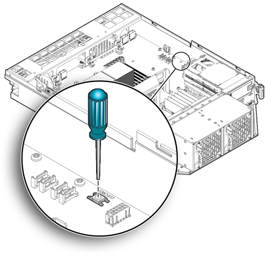
- Return the server node to operation.
- Install the server node top cover.
- Install the server node into the system.
- Power on the server node.
See Powering On Oracle Database Appliance Version 1.
When the server node powers on and boots, it displays a message that indicates that NVRAM has been cleared.
The CMOS NVRAM, including the BIOS password is cleared to its default state.
The default state for the BIOS passwords is that no password is required. To set a BIOS password, see BIOS Security Menu Screen.
- Verify that the Power/OK LED is lit on the server node.
Ethernet Port Naming and Boot Order
Note:
Information in this appendix does NOT apply to Oracle Database Appliance X3-2, Oracle Database Appliance X4-2, Oracle Database Appliance X5-2 or Oracle Database Appliance X6 series. Refer to the preceding chapters in this document for information on servicing those systems.Each Oracle Database Appliance Version 1 server node supports two 10/100/1000Base-T Gigabit Ethernet ports on the rear of the chassis. For port locations, see the Oracle Database Appliance Owner's Guide.
The device naming for the Ethernet interfaces is reported differently by different interfaces and operating systems. See the following table for the physical (BIOS) and logical (operating system) naming conventions used for each interface.
| Interface | NET0 | NET1 |
|---|---|---|
|
BIOS |
NET0 |
NET1 |
|
Oracle Linux |
eth0 |
eth1 |
The order in which the BIOS detects the Ethernet ports during boot time, and the corresponding drivers that control those ports, are listed below:
-
NET 0 (INTEL NIC 0)
-
NET 1 (INTEL NIC 1)
Configuring Support for TPM
Note:
Information in this appendix does NOT apply to Oracle Database Appliance X3-2, Oracle Database Appliance X4-2, Oracle Database Appliance X5-2 or Oracle Database Appliance X6 series. Refer to the preceding chapters in this document for information on servicing those systems.If you intend to use the Oracle Database Appliance Version 1 Trusted Platform Module (TPM) feature set, you must configure the server node to support this feature.
TPM enables you to administer the TPM security hardware in your server node. For additional information about implementing this feature, see the Trusted Platform Module Management documentation.
Configure TPM Support in BIOS
Note:
Information in this appendix does NOT apply to Oracle Database Appliance X3-2, Oracle Database Appliance X4-2, Oracle Database Appliance X5-2 or Oracle Database Appliance X6 series. Refer to the preceding chapters in this document for information on servicing those systems.- Access the BIOS Setup Utility menus.
For instructions, see Accessing the BIOS Setup Utility Menus.
When BIOS is started, the main BIOS Setup Utility top-level System Overview screen appears.
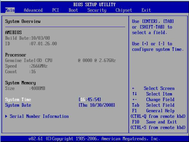
- In the BIOS Setup Utility screen, select the Advanced menu option.
The Advanced Settings screen appears.
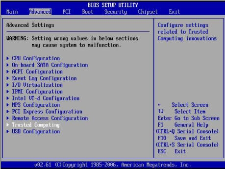
- In the Advanced Settings screen, select Trusted Computing and press Enter.
The Trusted Computing screen appears.
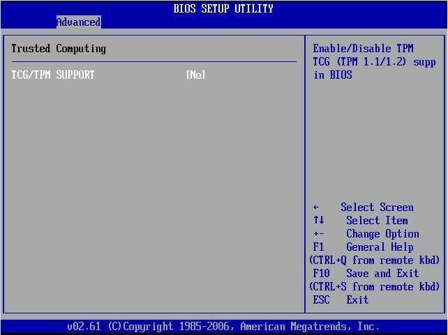
- In the Trusted Computing screen, select the TCG/TPM Support.
A pop-up dialog box appears.
- In the pop-up dialog box, set the TCG/TPM Support option to Yes and click OK.
Note:
Even if the TCG/TPM Support was already set to Yes in the dialog shown above, continue on and complete the remaining steps of this procedure to ensure that all TPM configuration requirements are satisfied.The updated Trusted Computing dialog appears and shows that the TCG/TPM Support setting has changed to Yes.
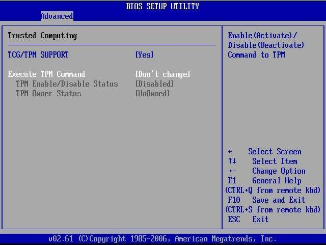
Note:
In the above screen, the Execute TPM Command setting shows the default, Don't Change. - In the Trusted Computing screen, select the Execute TPM Command option setting.
A pop-up dialog box appears.
- In the pop-up dialog box, set the Execute TPM Command option to Enabled and click OK.
The updated Trusted Computing screen appears and shows that the Execute TPM Command setting has changed to Enabled.
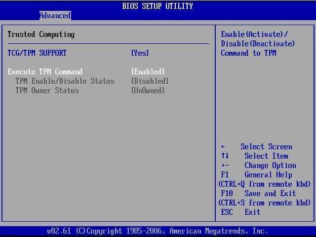
- Press F10 to save the changes and exit the BIOS Setup Utility.
- To verify that TPM support is configured, do the following:
- Reboot the server node.
- To enter the BIOS Setup Utility, press the F2 key while the system is performing the power-on self-test (POST).
When BIOS is started, the main BIOS Setup Utility top-level screen appears.
- Select Advanced, then select Trusted Computing and press Enter.
The updated Trusted Computing screen appears.
Confirm that the TCG/TPM Support setting is set to Yes and the TPM Enabled/Disable Status is set to Enabled.
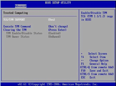
- Press F10 to exit the BIOS Setup Utility.
This completes the TPM configuration.
Configuring SP LAN Settings
Note:
Information in this appendix does NOT apply to Oracle Database Appliance X3-2, Oracle Database Appliance X4-2, Oracle Database Appliance X5-2 or Oracle Database Appliance X6 series. Refer to the preceding chapters in this document for information on servicing those systems.You can assign an IP address for the Oracle Database Appliance Version 1 server node SP from the BIOS Setup Utility on the IPMI LAN configuration menu. Alternatively, you can also specify the LAN settings for the SP using Oracle ILOM. For instructions for setting the IP address in Oracle ILOM, see Oracle Integrated Lights Out Manager (Oracle ILOM) 3.0 Documentation Collection.
Configure LAN Settings for SP
- Access the BIOS Setup Utility menus.
For instructions, see Accessing the BIOS Setup Utility Menus.
- In the BIOS Setup Utility menus, use the arrow keys (or Tab key) to navigate to the Advanced menu.
- In the Advanced menu, select IPMI Configuration.
- In the IPMI Configuration menu, select LAN Configuration.
The LAN Configuration screen appears.
- In the LAN Configuration screen, use the arrow keys to select and specify the appropriate LAN configuration settings.
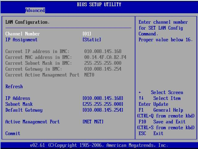
- After making the necessary changes, select Commit and press Enter to apply the changes.
- Press F10 to save the changes and exit BIOS.
Configuring Option ROM Settings in BIOS
Note:
Information in this appendix does NOT apply to Oracle Database Appliance X3-2, Oracle Database Appliance X4-2, Oracle Database Appliance X5-2 or Oracle Database Appliance X6 series. Refer to the preceding chapters in this document for information on servicing those systems.The Oracle Database Appliance Version 1 BIOS Option ROM space is 128 Kbytes. Of these 128 Kbytes, approximately 80 Kbytes are used by the VGA controller, the disk controller, and the network interface card. Approximately 48 Kbytes remain to be shared by the Option ROMs on all bootable PCI-Express plug-in cards.
Enable or Disable Option ROM Settings
Note:
Information in this appendix does NOT apply to Oracle Database Appliance X3-2, Oracle Database Appliance X4-2, Oracle Database Appliance X5-2 or Oracle Database Appliance X6 series. Refer to the preceding chapters in this document for information on servicing those systems.- Access the BIOS Setup Utility menus.
For instructions, see Accessing the BIOS Setup Utility Menus.
- In the BIOS Setup Utility menus, use the arrow keys (or Tab key) to navigate to the Boot menu.
The Boot menu appears.
- In the Boot menu, highlight the Option ROM setting, and then press Enter.
- Check whether the settings in your screen output match what is shown above. If they do not match, proceed to the next step. If they match, proceed to Step 7 and exit BIOS.
- To change the settings, in the Boot menu listing the Option ROM settings, highlight the applicable Option ROM setting to modify, then press Enter.
A dialog box appears listing the available settings.
- In the dialog box, do one of the following:
- Select –Enabled to enable the Option ROM setting.
- Select –Disabled to disable the Option ROM setting.
- Press F10 to save the changes and exit the BIOS Setup Utility.
BIOS Setup Utility Hot Keys
Note:
Information in this appendix does NOT apply to Oracle Database Appliance X3-2, Oracle Database Appliance X4-2, Oracle Database Appliance X5-2 or Oracle Database Appliance X6 series. Refer to the preceding chapters in this document for information on servicing those systems.The following table provides a description of the Oracle Database Appliance Version 1 BIOS Setup Utility Oracle ILOM Remote Console keys and the directly attached keyboard keys, and the corresponding serial connection key combinations.
| Oracle ILOM Remote Console Keys | Serial Connection Hot Key Combinations | Function |
|---|---|---|
|
F1 |
Ctrl+Q (Press and hold the Control key and type Q) |
Access the BIOS Setup Utility if there is an error during the boot process. |
|
F2 |
Ctrl+E |
Enter BIOS Setup Utility when the system has completed the power-on self-test (POST). |
|
F7 |
Ctrl+D |
Discard changes, but do not exit. |
|
F8 |
Ctrl+P |
Select the BBS Popup menu, which allows you to select a boot device. |
|
F9 |
Ctrl+O |
Load optimal BIOS defaults. |
|
F10
F10 is not supported on the Oracle ILOM Remote Console; instead, use the arrow keys to navigate to the Exit menu and press Enter. |
Ctrl+S |
Save changes and exit. |
|
F12 |
Ctrl+N |
Boot the server node from the network (PXE boot). |
Accessing the BIOS Setup Utility Menus
Note:
Information in this appendix does NOT apply to Oracle Database Appliance X3-2, Oracle Database Appliance X4-2, Oracle Database Appliance X5-2 or Oracle Database Appliance X6 series. Refer to the preceding chapters in this document for information on servicing those systems.You can access Oracle Database Appliance Version 1 BIOS Setup Utility screens from the following interfaces:
-
Use a USB keyboard, mouse, and VGA monitor connected directly to the server node.
-
Use a terminal (or terminal emulator connected to a computer) through the serial port on the back panel of the server node.
-
Connect to the server node using the Oracle ILOM Remote Console.
The following procedure describes the steps for accessing the BIOS Setup Utility menus.
Access BIOS Setup Utility Menus
Note:
Information in this appendix does NOT apply to Oracle Database Appliance X3-2, Oracle Database Appliance X4-2, Oracle Database Appliance X5-2 or Oracle Database Appliance X6 series. Refer to the preceding chapters in this document for information on servicing those systems.- Power-on or power-cycle the server node.
- The following information appears on the screen:
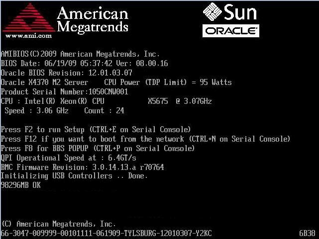
- To enter the BIOS Setup Utility, do the following:
- Wait for the last line of the screen output to change to Initializing USB Controllers..Done
This will take several seconds.
- When Done appears, press the F2 key immediately.
Note:
If there is an error during the boot process, you can press F1 to access the BIOS Setup Utility.The BIOS Setup Utility dialog appears.

Note:
If the BIOS Setup Utility dialog does not appear, you waited too long to press the F2 key. When Done appears on the screen, you must press the F2 key immediately. Try again.
- Wait for the last line of the screen output to change to Initializing USB Controllers..Done
- Use the left and right arrow keys to select the different menu options.
- As you select each menu option, the top-level screen for that menu option appears.
- To select an option on a top-level screen, use the up and down arrow keys to scroll up and down the options presented.
Only options that can be modified are highlighted when you press the up and down arrow keys.
- If a field can be modified, as you select the option, user instructions for modifying the option appear in the right column of the screen.
- If a field is a link to a sub-screen, instructions to press the Enter key to access the sub-screen appear in the right column.
- Modify the setup field and press the Esc key to save the changes and exit the screen.
Some screens present a confirmation dialog box that enables unwanted changes to be retracted.
- On sub-screens that only provide configuration information and cannot be modified, press the Esc key to exit the screen.
- To continue modifying other setup parameters, repeat Step 4 through Step 8. Otherwise, go to Step 10.
- Press and release the right arrow key until the Exit menu screen appears.
- Follow the instructions on the Exit menu screen to save or discard your changes and exit the BIOS Setup Utility.
BIOS Setup Utility Screens
Note:
Information in this appendix does NOT apply to Oracle Database Appliance X3-2, Oracle Database Appliance X4-2, Oracle Database Appliance X5-2 or Oracle Database Appliance X6 series. Refer to the preceding chapters in this document for information on servicing those systems.This section describes the Oracle Database Appliance Version 1 BIOS setup utility screens. It includes the following sections:
The BIOS utility includes seven top-level screens, many of which include sub-screens. Arrow keys provide navigation, and the options or fields that you can configure appear in color. Online instructions provide additional information.
Note:
The screens shown are examples. The version numbers and the screen items and selections shown are subject to change over the life of the product.BIOS Setup Utility Screen Overview
Note:
Information in this appendix does NOT apply to Oracle Database Appliance X3-2, Oracle Database Appliance X4-2, Oracle Database Appliance X5-2 or Oracle Database Appliance X6 series. Refer to the preceding chapters in this document for information on servicing those systems.The following table contains summary descriptions of the Oracle Database Appliance Version 1 top-level BIOS setup screens.
| Screen | Description | See This Section |
|---|---|---|
|
Main |
General product information, including BIOS type, processor, memory, and time/date. |
|
|
Advanced |
Configuration information for the CPU, memory, IDE, Super IO, trusted computing, USB, PCI, MPS and other information. |
|
|
PCI |
Configure the system to clear NVRAM during system boot. |
|
|
Boot |
Configure the boot device priority (storage drives and boot disk drives). |
|
|
Security |
Set or change the user and supervisor passwords. |
|
|
Chipset |
View the configuration of system chip set. |
|
|
Exit |
Save changes and exit, discard changes and exit, discard changes, or load optimal or fail-safe defaults. |
The following figures shows a map of the BIOS screens.
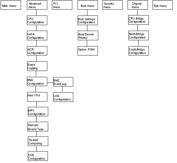
BIOS Main Menu Screen
The Oracle Database Appliance Version 1 BIOS Main screen provides general product information, including BIOS, processor, system memory, and system time/date.

BIOS Advanced Menu Screen
The Oracle Database Appliance Version 1 BIOS Advanced screen provides detailed configuration information for the CPU, memory, IDE, Super IO, trusted computing, USB, PCI, MPS and other system information.
BIOS PCI Menu Screen
The Oracle Database Appliance Version 1 BIOS PCI screen enables you to configure the server node to clear NVRAM during system boot.
BIOS Boot Menu Screen
The Oracle Database Appliance Version 1 BIOS Boot screen enables you to configure the boot device priority (storage drives and the DVD-ROM drive).
BIOS Security Menu Screen
The Oracle Database Appliance Version 1 BIOS Security screen enables you to set or change the supervisor and user passwords. The default state is for the passwords to be unconfigured (not required).
-
If you configure a supervisor password, users must enter it to access BIOS setup.
-
If you configure a user password, users must enter it before booting an OS.
BIOS Chipset Menu Screen
The Oracle Database Appliance Version 1 BIOS Chipset screen enables you to set the chipset parameters.
BIOS Exit Menu Screen
The Oracle Database Appliance Version 1 BIOS Exit options enable you to save changes and exit, discard changes and exit, discard changes, or load optimal defaults.
Exit From the BIOS Setup Utility
- Use the up and down arrow keys to scroll up and down the BIOS Exit options.
- Press Enter to select the option.
A confirmation dialog box appears that enables you to save the changes and exit the Setup Utility or cancel the exit option.
Note:
The confirmation dialog box is only shown below for the Save Changes and Exit option screen. The other exit confirmation screens work in a similar way.