Before defining a non-CMP cluster, ensure the following:
- The server software is installed on all servers in the cluster.
- The servers have been configured with network time protocol (NTP), domain name server (DNS), IP Routing, and OAM IP addresses.
- The server IP connection is active.
- The server software is running on at least one server.
To set up a non-CMP cluster:
- From the Platform Setting section of the navigation pane, select Topology Settings.The Cluster Configuration page opens; the initial group is All Clusters.
- From the work area, select Add MPE/MRA/Mediation Cluster.Note: The list of available cluster types to add to the topology depends on the CMP modes configured. See the CMP Wireless User's Guide for more information.The Topology Configuration page opens.
- In the Cluster Settings section of the page:
- (Required) Enter the Name for the cluster.The name can only contain the characters A through Z, a through z, 0 through 9, period (.), hyphen (-), and underline (_). The maximum length is 250 characters.
- Select the Appl Type from the list.Available options are:
- MPE (default)
- MRA
- Mediation
Note: The list of available application types depends on the CMP modes configured. See the CMP Wireless User's Guide for more information. - Select the HW Type from the list.Available options are:
- C-Class (default)—HP ProLiant BL460 Gen8 server
- C-Class (Segregated Traffic) (a configuration where Signaling and other networks are separated onto physically separate equipment) – HP ProLiant BL460 Gen8
- Oracle RMS—Oracle Server X5-2
- RMS (rack-mounted server)—HP ProLiant DL380 Gen8 server
- VM (virtual machine)
- VM(Automated) (VM managed by NF Agent)
See Setting Up a VM (Automated) Non-CMP Cluster for details on adding a VM (Automated) cluster.
- (Required) To enter up to two OAM VIP (one IPv4 and one IPv6) addresses, click Add New VIP.The New OAM VIP dialog box appears.
- Enter the OAM VIP addresses and the Mask. This is the IP address the CMP server uses to communicate with a Policy Management cluster.Note: Enter the IPv4 address in standard dot format and its subnet mask in CIDR notation from 0 to 32, or the IPv6 address in standard 8-part colon-separated hexadecimal string format and its subnet mask in CIDR notation from 0 to 128.
- Click Save.
The OAM VIP address and Mask are saved.
- Enter the OAM VIP addresses and the Mask.
- If needed, repeat the process for the second OAM VIP.
- (Optional) To enter up to six Signaling VIPs addresses (up to two each for each of SIG-A, SIG-B, and SIG-C), click Add New VIP.The signaling VIP is the IP address a PCEF device uses to communicate with the cluster. A non-CMP cluster supports redundant communication channels, named SIG-A, SIG-B, or SIG-C for carriers who use redundant signaling channels.The New Signaling VIP dialog appears.
- Enter the Signaling VIP address and the Mask. This is the IP address the CMP server uses to communicate with an external signaling network.Note: Enter the IPv4 address in standard dot format and its subnet mask in CIDR notation from 0 to 32, or the IPv6 address in standard 8-part colon-separated hexadecimal string format and its subnet mask in CIDR notation from 0 to 128.
- Select the Interface from the list.Available options are:
- SIG-A
- SIG-B
- SIG-C
- Click Save.
The Signaling VIP address and Mask are saved.
- Enter the Signaling VIP address and the Mask.
- Repeat the process for any remaining Signaling VIPs.
- If the hardware type is C-Class, C-Class(Segregated Traffic), or Oracle RMS, configure the General Network settings:
- Enter the OAM VLAN ID.
The default value is 3.
- Enter the SIG-A VLAN ID.
The default value is 5.
- (Optional) Enter the SIG-B VLAN ID.
The default value is 6.
- (Optional) Enter the SIG-C VLAN ID.
The default value is 7.
- Enter the OAM VLAN ID.
- If the hardware type is C-Class or C-Class(Segregated Traffic), for the User Defined Network, enter the REP VLAN ID.Virtual LAN (VLAN) IDs are in the range of 1 to 4095.
- (Required) Enter the Name for the cluster.
- To configure Server-A hardware, in the Server-A section of the page:
- (Required) To enter the IP address, click Add New IP.The Add New IP dialog box appears.
- Enter the IP address in either IPv4 or IPv6 format.
The IP address of the server. For an IPv4 address, enter it in the standard IP dot-format. For an IPv6 address, enter it in the standard 8-part colon-separated hexadecimal string format.
- Select the IP Preference.Either IPv4 or IPV6. If IPv6 is selected, the server will preferentially use the IPv6 address for communication.Note: If neither an IPv6 OAM IP nor a static IP address is defined, IPv6 cannot be selected. If neither an IPv4 OAM IP nor a static IP address is defined, IPv4 cannot be selected.
- Enter the IP address in either IPv4 or IPv6 format.
- Enter the HostName of the server.The name can only contain the characters A through Z, a through z, 0 through 9, period (.), hyphen (-), and underline (_). This must exactly match the host name provisioned for this server (the output of the Linux command uname –n).Note: If the server has a configured server IP, you can click Load to retrieve the remote server host name. If the retrieve fails, you must enter the host name.
- Select Forced Standby to put Server-A into forced standby status.By default, Server-A will be the initial active server of the cluster.
- (Required) To enter the IP address, click Add New IP.
- (Optional) Click Add Server-B and enter the information for the standby server of the cluster.Server-B is defined for the cluster.
- Click Save.A confirmation message appears.
- Click OK.
The cluster is defined. To set up another cluster, repeat the steps.
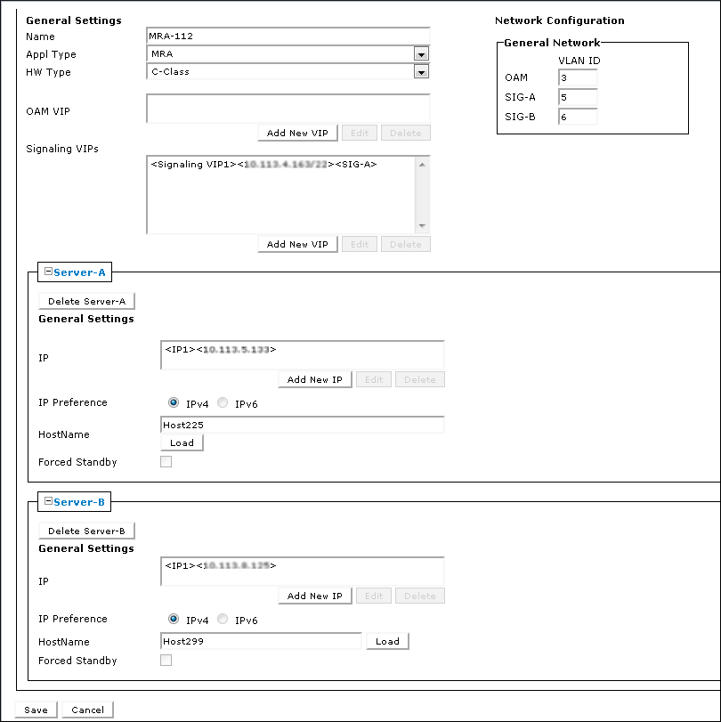
Figure 1 shows the configuration for a georedundant (two-site) MRA cluster, using SIG-B for a replication network and OAM for the backup heartbeat network, with eight WAN replication streams.
Sample MRA Cluster Topology Configuration