Go to primary content
Oracle® Communications EAGLE SIGTRAN User's Guide
Release 46.6
E97352 Revision 1
Go To Table Of Contents
Contents

Previous
Previous
Next
Next

IPGW/M3UA deployment scenarios

Active/standby configurations

Figure A-2 IPGWx active/standby configuration

  • Active/standby configurations should be implemented at the IP Signaling Points (IPSPs) rather than at the EAGLE.
  • All DCMs assigned to an IPGWx mateset should host connections to nodes comprising an Application Server and should loadshare traffic in the absence of failures. Deployments of active/standby DCMs result in excessive IMT utilization in the absence of failures due to double-hopped outbound traffic.

Two-pair IPGWx

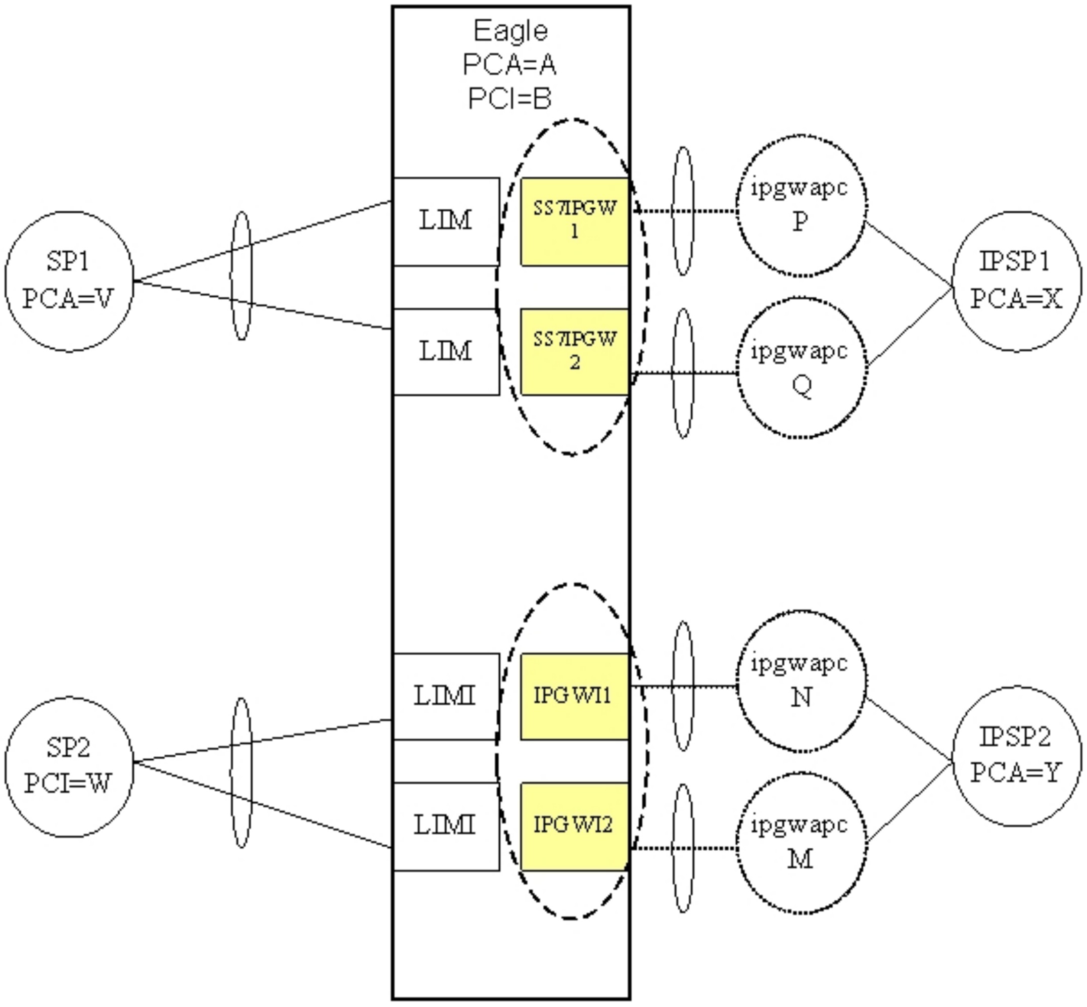
Figure A-3 Two-Pair IPGWx for maximum TPS

  • Two IPGWx cards are deployed as a mateset. No more than two cards for each application are allowed.
  • Each card has one signaling link, represented by a hatched line. Each IPGWx signaling link is alone in a linkset, represented by an ellipse.
  • Each card has a fake adjacent signaling point represented by a hatched circle and having an IPGWx Adjacent Point Code. Each of the IPGWx linksets has an IPGWAPC.
  • Two equal cost routes are provisioned for X, thereby combining the two SS7IPGW linksets. Two equal cost routes are provisioned for Y, thereby combining the two IPGWI linksets.
  • Each card has one or more IP connections to the IPSP, represented by a solid line. Each IP connection has only an indirect relationship to a signaling link.
  • If each card is rated at 2,000 TPS, then the maximum transaction rate to/from a point code is 2,000 TPS (1+1 redundancy), and the total system-wide TPS supported is 4,000 TPS.
  • This feature will continue to allow the preceding deployment (two pairs, combined linksets) to be used, and will expand the number of deployment variations supported. It will do this by modifying the definition of a SS7IPGW or IPGWI mateset.

Four IPGWx pairs

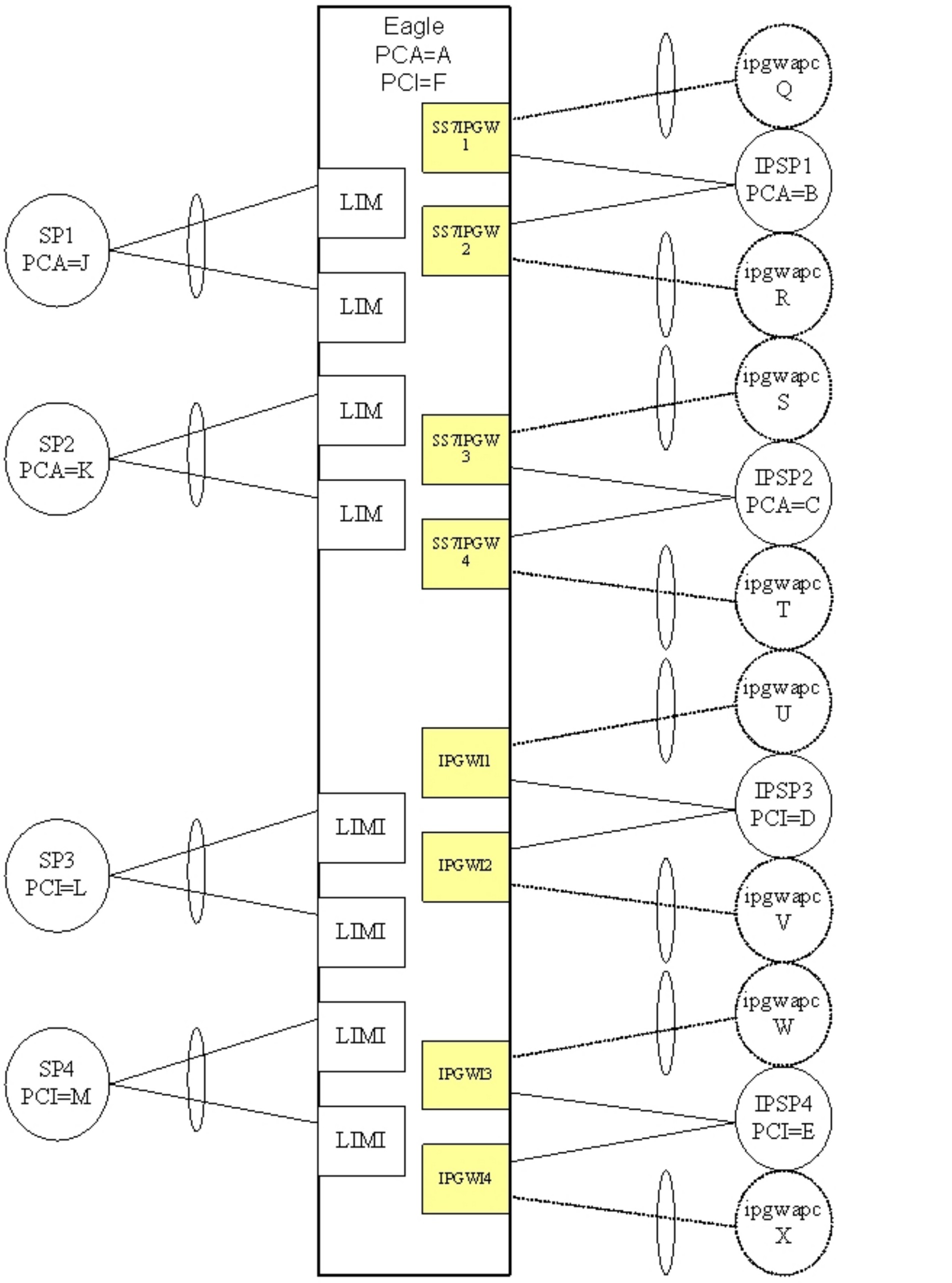
Figure A-4 Four IPGWx pairs (two SS7IPW pairs and two IPGWI pairs)

  • There are four IPGWx matesets, each comprised of two linksets (a combined linkset).
  • Each IPSP is only connected to cards within an IPGWx mateset. No IPSP (or Application Server) crosses IPGWx mateset boundaries.
  • This deployment is 1+1 redundancy.
  • Another supported variation of this deployment would involve different numbers pairs or linksets, and possibly one linkset per pair.

Eight IPGWx cards

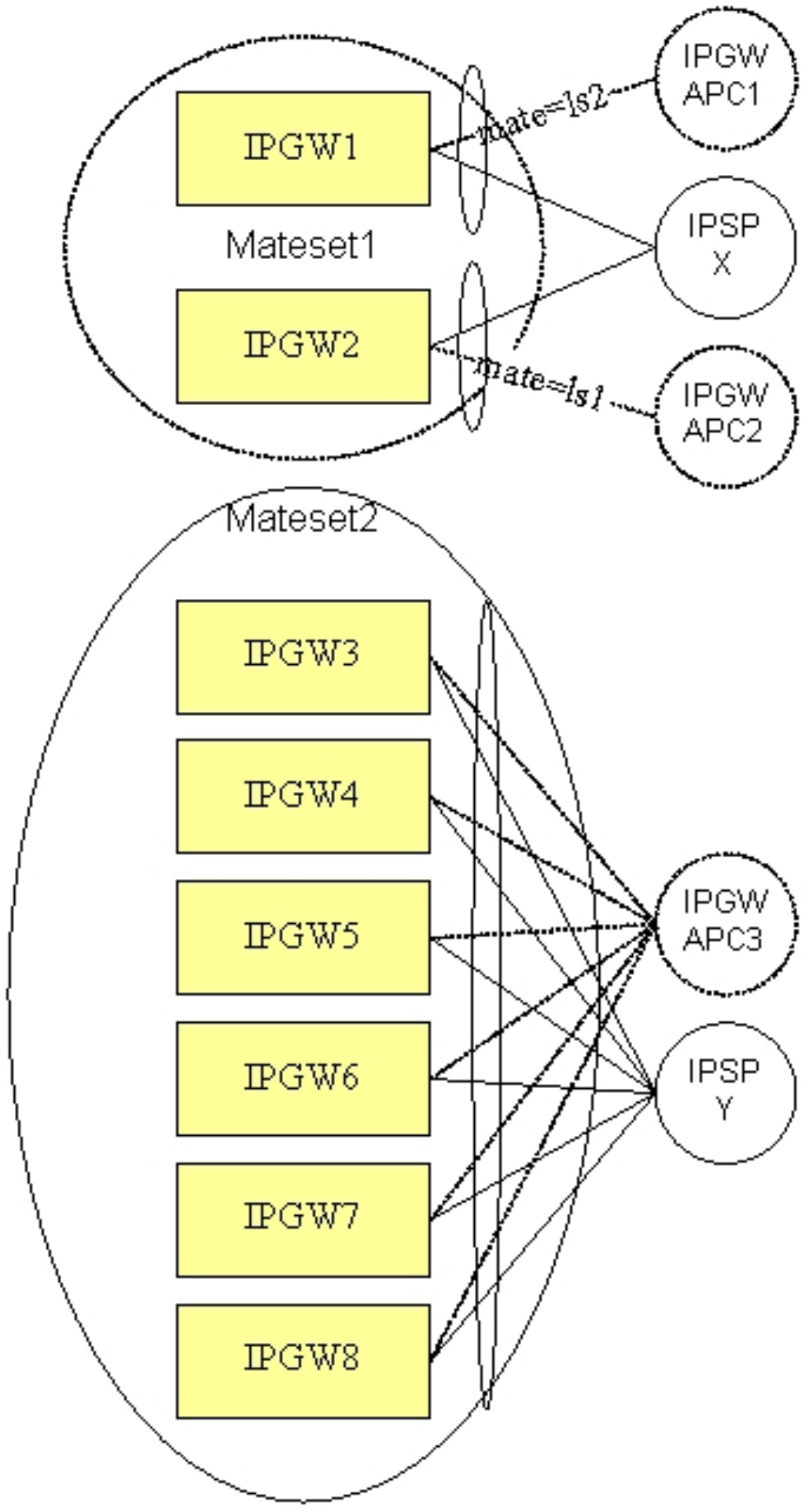
Figure A-5 Eight IPGWx cards, two mates, three linksets
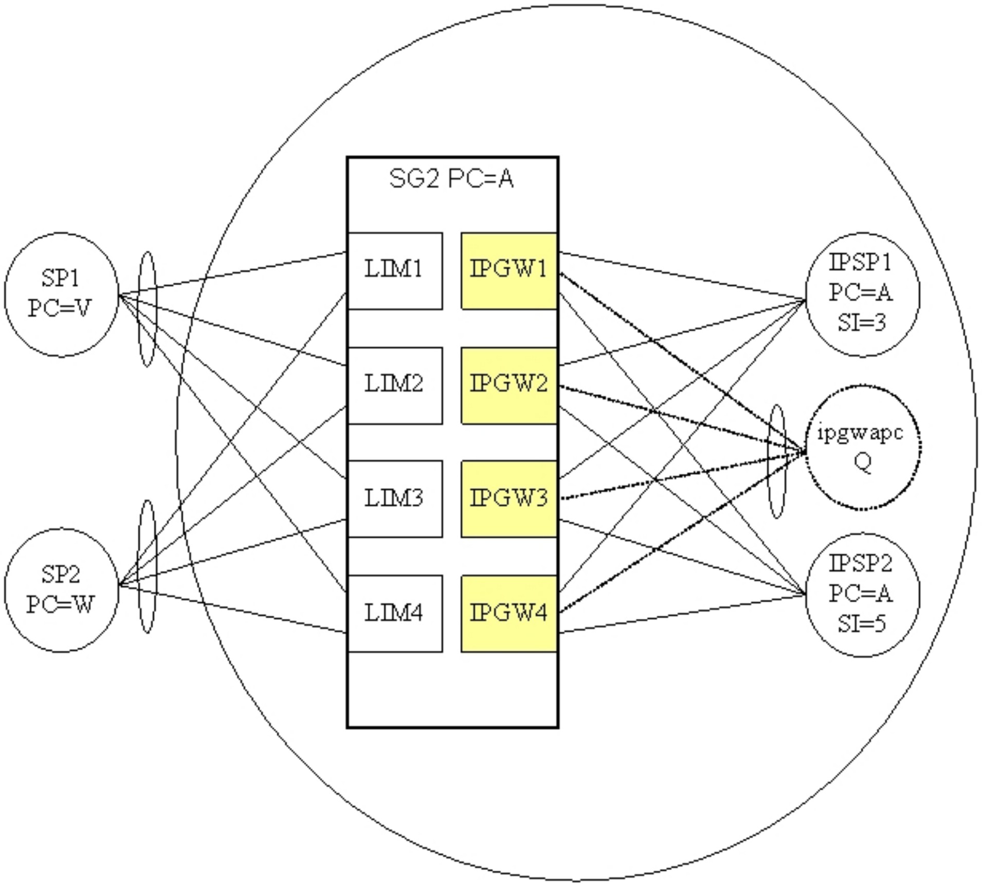
  • Eight IPGWx cards are present, each having a single signaling link. IPGW1 and IPGW2 have their links assigned to distinct linksets. The remaining IPGWx cards have their links assigned to a common linkset.
  • The route-set to PC X involves a combined linkset, i.e. two equal-cost routes.
  • Connectivity to the IPSPs does not cross IPGWx mateset boundaries.
  • More than two IPSPs can be supported in either IPGWx mateset. The actual limit is based on IP connections and routing keys.
  • Other supported variations of this deployment involve different numbers of cards in the Mateset2 or different numbers of IPSPs.

Four IPGWx cards

Figure A-6 Four IPGWx cards, one linkset for end office

  • Four IPGWx cards are present, each having a single signaling link. All of the IPGWx signaling links are assigned to a linkset having an IPGWAPC (virtual point code) of Q.
  • Two IP-based signaling points or Application Servers are each connected to the full set of IPGWx cards and are distinguished by user part (SI).
  • Because the IPGWx signaling links are part of a single linkset, each card cannot use TFP/TFA to divert traffic to other IPGWx cards.
  • The EAGLE is operating in End Office Mode. This means that the IPSPs are IP-attached remote user-parts that share the true and secondary point codes of EAGLE (PC=A). In order to route from the inbound LIMs to the outbound IPGWx cards, an internal point code (IPC) is used.
  • Because only one IPC is currently supported, only one IPGWx mateset is supported for End Office mode traffic. There can be other IPGWx matesets, but only one can serve End Office remote applications.
  • Other supported variations of this deployment involve different numbers of cards in the mateset or different numbers of IPSPs.

Unsupported Scenarios

Figure A-7 shows that the route to IPGWx linksets 1 and 2 are combined. Combined linksets are not supported.

Figure A-7 Unsupported deployment scenario: combined linksets (1)

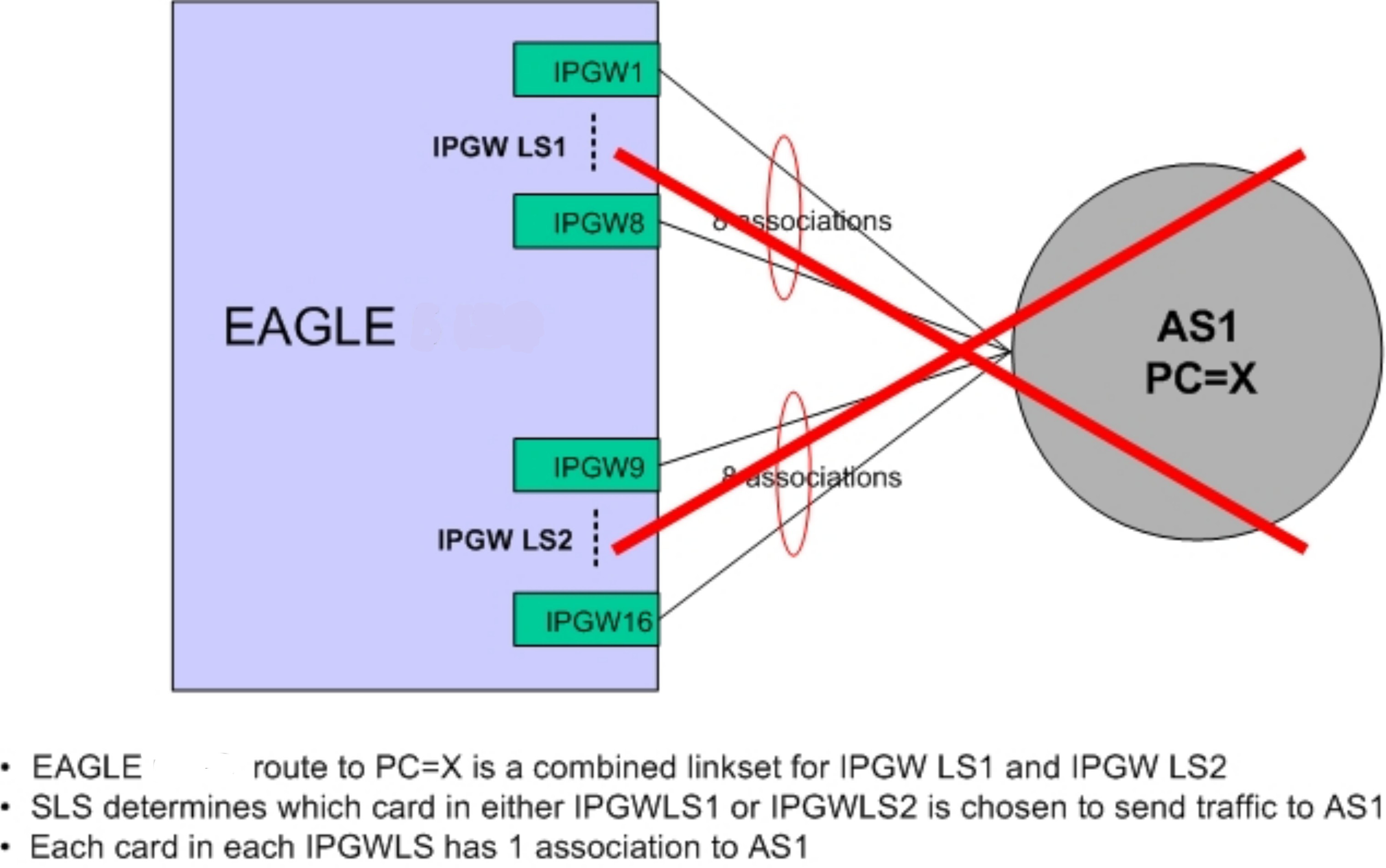
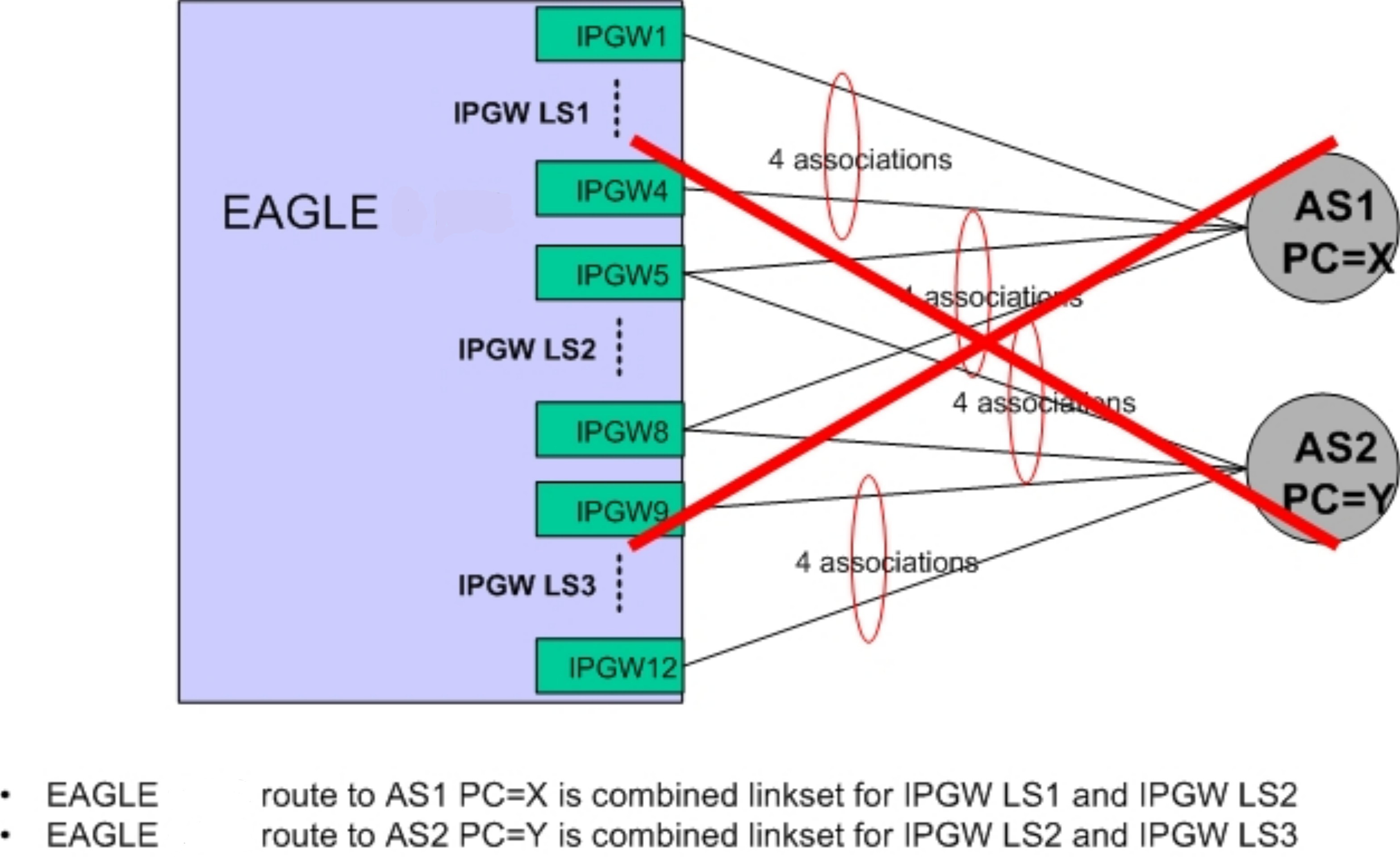
Figure A-8 shows that the route to IPGWx linksets 1 and 2 are combined for AS1; and linksets 2 and 3 are combined for AS2. Combined linksets are not supported.

Figure A-8 Unsupported deployment scenario: combined linksets (2)