IPGWx links and IPSG-M3UA links cannot co-exist in the same linkset for the following reasons:
- IPGWx linksets require provisioning of Routing Keys and Application Server (AS) table entries in the EAGLE to communicate with M3UA ASs; IPSG-M3UA linksets require only SS7 routes, since the IPSG-M3UA linkset defines the scope of the AS
- The M3UA AS’s point code is a non-adjacent route accessed by a provisioned EAGLE Routing Key for an IPGWx linkset; this point code is the adjacent point code of an IPSG-M3UA linkset. This results in significant differences in network management behavior between IPGWx and IPSG-M3UA
- IPSG implements IP TPS control with subtle differences from IPGWx that result in incompatibilities
IPGWx M3UA AS must have the following attributes to qualify for conversion to IPSG-M3UA linksets:
- The Routing Key(s) used by the M3UA AS must be DPC-only; or the use of DPC-only Routing Key(s) would not degrade current or planned capability
- The M3UA AS-Pending procedure using a non-zero value for T (recovery) must not be a critical function provided by the Signaling Gateway
- M3UA ASP Failure notifications must not be a critical function provided by the Signaling Gateway
- The number of IPGWx-M3UA Application Servers to be converted to IPSG-M3UA linksets must not result in the total EAGLE link or linkset limits being exceeded. A maximum of 2,000 links and 1,024 linksets are supported.
- IPGWx cards that will be redeployed as IPSG cards MUST be E5-ENET or E5-ENET-B cards.
The method by which a customer migrates from existing IPGWx M3UA deployments to IPSG-M3UA deployments will vary based primarily on the following:
- The number of Routing Keys and ASs provisioned on the IPGWx linkset being converted
- The IPGWx redundancy model used
- The connected AS’s reliance on AS procedures
- The connected AS’s maximum supported number of connections and attached Signaling Gateways
Examples of typical deployments and possible conversion strategies are listed below, but contact your Oracle Communications sales representative to assist in planning an actual conversion:
The chg-card command allows the IPLIM application running on E5-ENET, E5-ENET-B, or SLIC cards to be migrated to the IPSG application, if the following requirements are met:
- The IPLIM application must be running on an E5-ENET, E5-ENET-B or SLIC card.
- The hardware can be changed to IPSG running on E5-ENET, E5-ENET-B cards or SLICs.
- The card must be manually inhibited prior to successful execution of the change command
- All IP associations configured for the card must use adapter type M2PA.
- Al links configured for the card must have an association configured.
- The migrated IPSG card TPS and system TPS must pass limit checks.
- The card must be manually allowed after successful execution.
Note:
If changing the configuration from IPLIM to IPSG exceeds the Transactions per Second (TPS) limits of the card or system, then the command is rejected.
If the chg-card command will not be used, then it is highly recommended that ProComm scripts or other automated EAGLE provisioning functionality be used to further mitigate risk.
IPGWx to IPSG-M3UA Conversion Example 1
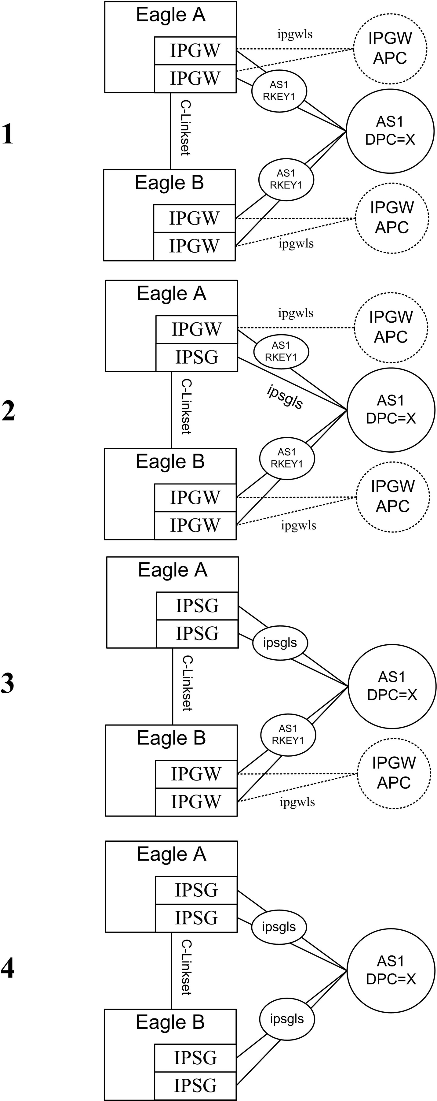
Figure 6-1 depicts one strategy to convert a simple IPGWx deployment to IPSG-M3UA.
The IPGWx deployment shown in #1 of
Figure 6-1 has the following attributes:
- Each STP in the mated pair of STPs utilizes a single IPGWx card to provide connectivity to AS1
- Each IPGWx card hosts a single M3UA association referenced by AS1
- AS1 is referenced by a single DPC-only Routing Key with DPC=X in each STP
The configuration shown in #2 of
Figure 6-1is a result of the following steps:
- The IPGWx signaling link in the top EAGLE is gracefully removed from service.
- The Routing Keys for AS1/DPC=X and AS1 are deleted from the EAGLE database.
- The M3UA association settings are recorded for use when the association is re-entered on the IPSG card.
- The M3UA association is deleted from the EAGLE database .
- The SS7 routes to DPC X and the IPGWx APC are deleted from the EAGLE database.
- The IPGWx Signaling Link and Linkset is deleted from the EAGLE database.
- The IP-CARD, IP-LNK, and IP-RTE settings for the IPGWx card are recorded. These settings are not preserved when the IPGWx card is deleted.
- The IPGWx card is deleted from the EAGLE database and entered as an IPSG card (assumes that there is an E5-ENET, E5-ENET-B or SLIC card in the slot).
- The IP-CARD, IP-LNK, and IP-RTE entries are updated in the EAGLE database for the new IPSG card with the setting recorded for the IPGWx card prior to its deletion.
- An M3UA association is entered into the EAGLE database and is updated with any non-default settings recorded for the IPGWx association prior to its deletion.
- A new IPSG-M3UA linkset with
APC=X is provisioned in the EAGLE database with the appropriate SLKTPS.
- A single IPSG-M3UA SLK is added to the IPSG-M3UA linkset referencing the M3UA association that is hosted by the IPSG card.
- An SS7 route to DPC X over the IPSG-M3UA linkset is entered into the EAGLE database. The relative cost of this route is determined by the customer’s requirements and approach to proving and soaking the IPSG-M3UA link. Initially, it may be desirable for the cost of the route over the IPSG-M3UA linkset to be higher than the cost of the route over the C-linkset; however, it should be noted that this approach will not prevent the AS from sending SS7 traffic over the IPSG-M3UA link once the IPSG-M3UA link becomes IS-NR.
- The IPSG-M3UA association is opened and SCTP connectivity is confirmed. The state of the IPSG-M3UA SLK should be
OOS-MT-DISABLED. The state of the AS-ASP instance should be ASP-INACTIVE, assuming the ASP is not administratively blocked at the AS.
- The IPSG-M3UA SLK is activated; it's state should become IS-NR. The state of the AS-ASP instance should be ASP-ACTIVE, assuming the ASP is not administratively blocked at the AS.
- The cost of the SS7 route to DPC X in EAGLE A is adjusted as appropriate to allow/prevent EAGLE A from using the IPSG-M3UA linkset to deliver MSU traffic destined for DPC X.
The configuration shown in #3 of Figure 6-1 is a result of utilizing the same steps used in EAGLE A to convert the IPGWx linkset in EAGLE B to IPSG-M3UA.
IPGWx to IPSG-M3UA Conversion Example 2
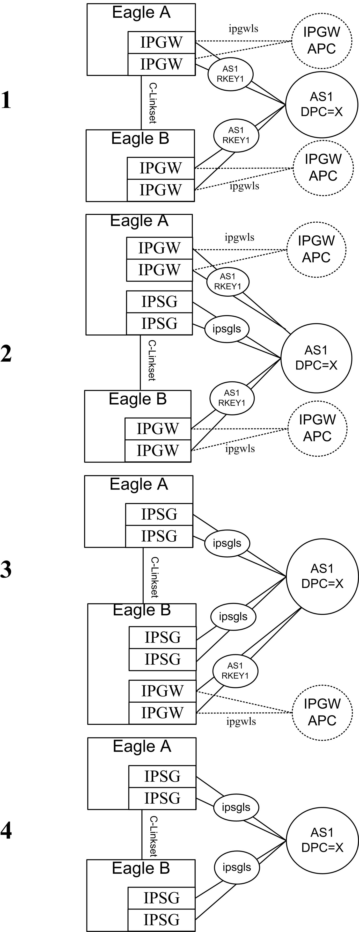
Figure 6-2 depicts one strategy to convert a more complex IPGWx deployment to IPSG-M3UA.
It should be noted that the IPGWx deployment shown in #1 of Figure 6-2 has the following attributes:
- Each STP in the mated pair of STPs utilizes two IPGWx cards to provide connectivity to AS1
- Each IPGWx card hosts a single M3UA association referenced by AS1
- AS1 is referenced by a single DPC-only Routing Key with DPC=X in each STP
The configuration shown in #2 of Figure 6-2 is a result of re-provisioning one of the IPGWx cards in EAGLE A to be a single-link IPSG-M3UA linkset with an APC of X, while leaving one of the original IPGWx links in place. From the M3UA AS’s perspective, provisioning the IPSG-M3UA link in EAGLE A while the remaining IPGWx links in EAGLE A and EAGLE B are still provisioned may be viewed as:
- Effectively connecting a third Signaling Gateway to the AS; this will be true if the AS relies on AS Notifications to operate correctly, since EAGLE treats AS1 over IPGWx linkset as a separate AS than AS1 over the IPSG-M3UA linkset.
OR
- No configuration change; this will be true if the AS does not rely on AS Notifications to operate correctly. In this case, AS notifications sent by EAGLE A are ignored by the AS and the IPSG-M3UA link is simply used as a path to the SS7 network if it is ACTIVE. The fact that the AS notifications sent by EAGLE A are not scoped across the IPGWx and the IPSG-M3UA linkset is not applicable. For ASs with this attribute, it may be desirable to disable AS notifications on the IPSG-M3UA linkset by setting the
asnotif linkset parameter to NO.
Similar to the earlier example, the relative cost of the route to DPC X over the IPSG-M3UA linkset in #2 of Figure 6-2 is dependent on the customer’s cutover strategy. It is important to note here again that the AS may begin sending SS7 traffic over the IPSG-M3UA link once the ASP becomes ACTIVE and the IPSG-M3UA link becomes IS-NR regardless of the relative cost of this route in the EAGLE.
The configuration shown in #3 of Figure 6-2 is a result of re-provisioning the remaining IPGWx card in EAGLE A to be an IPSG card hosting a single IPSG-M3UA link and adding the link to the existing IPSG-M3UA linkset connected to AS1. From the AS’s perspective, this change may be viewed as 1) reducing the number of connected Signaling Gateways back to the original two OR 2) no change. In either case, once the second IPSG-M3UA link is brought into service in EAGLE A, conversion activities are complete for EAGLE A.
The configuration shown in #4 of Figure 6-2 is a result of performing the same steps in EAGLE B as described for EAGLE A in steps #2 and #3.
IPGWx to IPSG-M3UA Conversion Example 2A
Figure 6-3 depicts an alternative strategy to convert the IPGWx configuration from the one described in IPGWx to IPSG-M3UA Conversion Example 2 to IPSG-M3UA.
The strategy shown in Figure 6-3 can be used to minimize risk and increase the flexibility in switching traffic between the IPGWx and IPSG-M3UA links and is dependent on:
- The customer’s willingness and ability to provision new E5-ENET, E5-ENET-B or SLIC cards and associated cabling and network connectivity for the IPSG links while leaving the existing IPGWx cards and associated cabling and network connectivity in place during the soak period
- The AS’s ability to support the configuration shown in #2 and #3 of Figure 6-3. As described earlier, the IPSG-M3UA linksets may be viewed by the AS as additional Signaling Gateway instances or simply additional M3UA connections to the SS7 network.
In #2 and #3 of Figure 6-3, the SS7 route cost for the routes to DPC X over the IPGWx linkset, the IPSG-M3UA linkset, and the C-linkset provides maximum control over which path is used to deliver MSUs destined for DPC X to the M3UA AS. It should be noted that multiple-link IPGWx linksets were not designed to be in combined linksets (i.e having SS7 routes to the connected ASs with equal cost to other SS7 routes in the same EAGLE) and so there exists the potential for the loadsharing across associations in a multiple link IPGWx linkset to be uneven when the IPGWx and IPSG-M3UA route costs are the same, especially if one or more SLKs or connections is not IS-NR.