| Oracle® Communications EAGLE Database Administration - SS7 User's Guide Release 46.6 E93318 Revision 1 |
|

 Previous |
 Next |
| Oracle® Communications EAGLE Database Administration - SS7 User's Guide Release 46.6 E93318 Revision 1 |
|
|
Previous |
Next |
Local Loopback Support
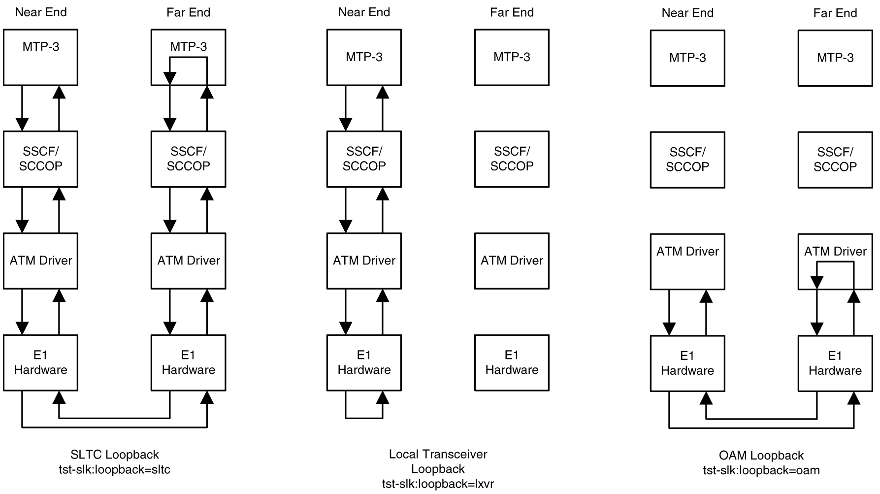
There are five link testing capabilities for an ATM high-speed signaling link. All five of these tests can be used for an ANSI ATM high-speed signaling link; three of these tests can be used for an E1 ATM high-speed signaling link. Table C-2 gives a description of each test and shows which the type of ATM high-speed signaling link each test can be used. Figure C-9 and Figure C-10 show diagrams of each test.
Table C-2 ATM High-Speed Signaling Link Loopback Support
| Loopback Type | ANSI ATM High-Speed Signaling Link | E1 High-Speed High-Speed Signaling Link | When can the Loopback Test be Performed | How does the Loopback test Work | What is Tested (Assume Near End Unless Specified) |
|---|---|---|---|---|---|
| SLTC |
Yes |
Yes |
When the link is in service and activated |
MTP-3 exchanges SLTM/SLTA messages with remote MTP-3. Appears as normal MSU traffic to SSCF and SSCOP. |
MTP-3 layer, ATM protocol stack (near end and far end), and wire |
| OAM |
Yes |
Yes |
When the link is connected to a remote STP. The state of the link is either activated or deactivated. |
ATM driver exchanges OAM F5 Loopback cells with remote ATM driver. One OAM cell per request with a maximum of three attempts made. |
ATM driver (near end and far end) and wire |
| LXVR |
Yes |
Yes |
When the link is deactivated. |
MTP-3 attempts to align link. If alignment fails, test fails. Appears as normal alignment request to SSCF and SSCOP. |
SSCF, SSCOP, ATM driver and T1 hardware (for an ANSI ATM high-speed link) or E1 hardware (for an E1 ATM high-speed signaling link) on near end |
| Payload |
Yes |
No |
When the link is deactivated, connected to remote STP and no Yellow Alarm BOC is being transmitted. |
MTP-3 attempts to align link. If alignment fails, test fails. Appears as normal alignment request to SSCF and SSCOP. |
SSCF, SSCOP, ATM driver (near end only) and T1 hardware (near end and far end) and wire |
| Line |
Yes |
No |
When the link is deactivated and connected to remote STP and no Yellow Alarm BOC is being transmitted. |
MTP-3 attempts to align link. If alignment fails, test fails. Appears as normal alignment request to SSCF and SSCOP. |
SSCF, SSCOP, ATM driver (near end only) and T1 hardware (near end and far end) and wire |
Figure C-9 ANSI ATM High-Speed Signaling Link Loopback Support
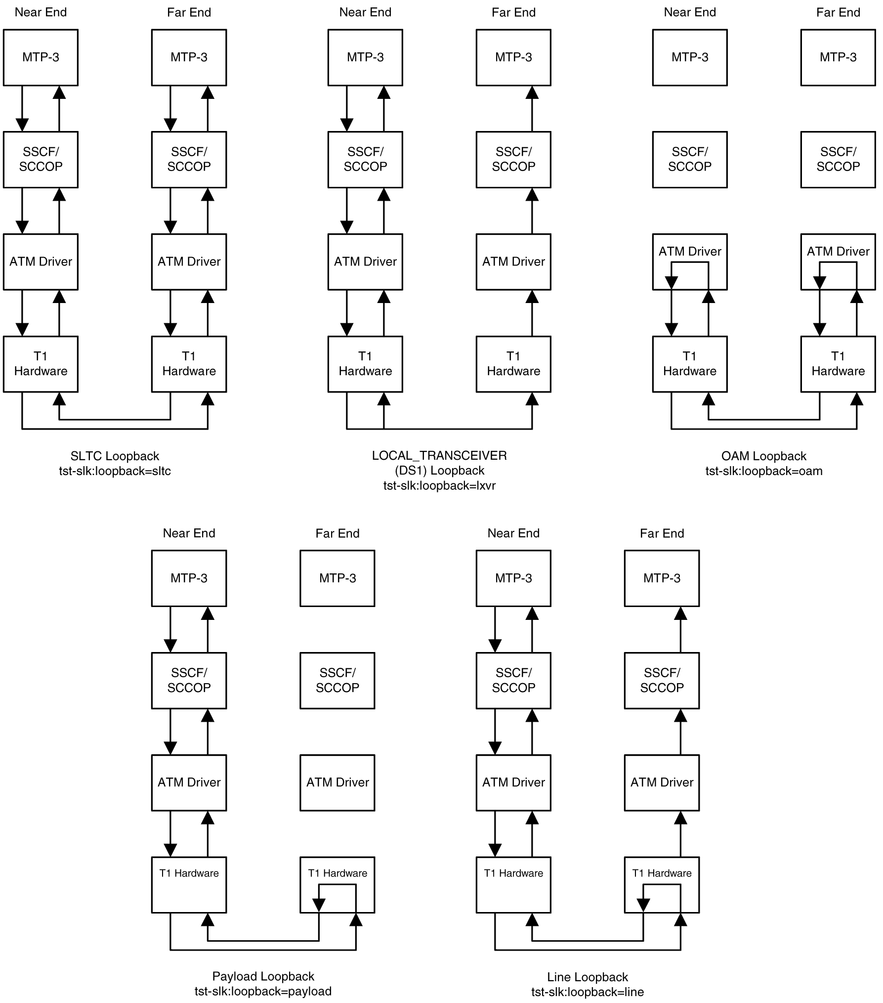
Figure C-10 E1 ATM High-Speed Signaling Link Loopback Support
Remote Loopback Support
The LIM containing the ATM high-speed signaling link must provide remote loopback support so that the EAGLE 5 ISS can act as the far end STP as shown in Figure C-9 or Figure C-10. The support provided for ATM high-speed signaling link cards is identical to low-speed signaling link cards by providing the same initialization and detection capabilities.
Link Status Logging Capability
The Enhanced Link Diagnostics capability stores link status information. The link status information is divided into 2 categories: service data and alignment data. Currently, each logging routine can store up to 69 events, all of which can be displayed using the rept-stat-slk command. The service data and alignment data categories are described in the following sections.
Service Data Category
Service events and their timestamps are buffered during transitions between the In-Service/Data Transfer Ready states and all other states. This buffer contains a history of the link failure reasons (as seen from Level 2’s point of view) and the subsequent realignments. Each entry in the buffer is either the link failure reason and time, or the time the link came back in service. Table C-3 provides a list of all high-speed signaling link failure reasons, however, not all of these failures will show up in the service data. Several types of failure that are recognized by Level 3 (like Changeover Order Received or Failed SLT) are mapped to a Stop Commanded event at Level 2. If the history indicates the link did not realign after the failure, the alignment data buffer shows the reason the link was unable to be realigned.
The service data history contains only the high-speed signaling link failure reason as seen by Level 2. As highlighted above, there actual failure reason can be hidden from the Level 2 Service Data if it is an event that is detected by level 3. For example, there are many reasons why Level 3 sends a Stop command to Level 2, such as link deactivated by user, changeover order received, false link congestion, etc. Therefore, the service data should only be used as a guide in determining a link failure.
Table C-3 High-Speed Signaling Link vs. Low-Speed Signaling Link Unavailability Reasons by Priority
| High-Speed Signaling Link Unavailability Reason | Low-Speed Signaling Link Unavailability Reason |
|---|---|
| Remote Loopback |
Remote Loopback |
| LOS |
|
| LOF |
|
| LCD |
|
| Too Many Interrupts |
Too Many Interrupts |
| Stopped Receiving Data |
|
| ISERM threshold exceeded |
|
| SUERM |
|
| Remote Out of Service |
|
| Remote Protocol Error |
|
| Remote Management Initiated |
|
| Remote Processor Outage |
|
| Local Processor Outage |
|
| Timer_No_Credit expired |
|
| Timer_No_Response expired |
|
| T1 expired(ready, not ready) |
|
| T3 expired |
|
| T2 expired |
|
| Exceeded Proving Period Count |
|
| SIO received |
|
| SIN received |
|
| SIE received |
|
| SIOS received |
|
| SIPO received |
|
| RC/BSNR link failure |
|
| RC/FIBR link failure |
|
| T6 expired |
|
| T7 expired |
|
| COO Received |
COO Received |
| False SLK Congestion |
False SLK Congestion |
| SLK Restart Delayed |
SLK Restart Delayed |
| Far End Loopback |
Far End Loopback |
| Link Not Aligned (default) |
Link Not Aligned (default) |
| Remote Blocked |
Remote Blocked |
| Local Blocked |
Local Blocked |
| Remote Inhibited |
Remote Inhibited |
| Local Inhibited |
Local Inhibited |
Alignment Data Category
Alignment events are buffered at all times when link is not in service. Only the first unique occurrence of an event and its timestamp is buffered. High-speed signaling link alignment events are divided into:
Table C-4 High-Speed Signaling Link State Transition Alignment Events
| SSCOP | SSCF | MAAL |
|---|---|---|
| Idle |
OOS Idle |
OOS |
| Outgoing Conn. Pending |
OOS ODP |
Alignment |
| Incoming Conn. Pending |
Alignment Idle |
Proving |
| Outgoing Disc. Pending |
Alignment OCP |
Aligned/Ready |
| Outgoing Resync Pending |
Alignment ODP |
In Service |
| Incoming Resync Pending |
Proving Data Transfer Ready |
|
| Outgoing Recovery Pending |
Aligned/Ready Data Transfer Ready |
|
| Recovery Response Pending |
In Service/Data Transfer Ready |
|
| Incoming Recovery Pending |
||
| Data Transfer Ready |
Table C-5 High-Speed Signaling Link Transmitted/Received Alignment PDUs
| SSCOP | SSCF |
|---|---|
| BGN |
Out of Service |
| BGAK |
Processor Outage |
| END |
In Service |
| ENDAK |
Normal |
| RS |
Emergency |
| RSAK |
Alignment Not Successful |
| BGREJ |
Mgmt Initiated |
| SD |
Protocol Error |
| ER |
Proving Not Successful |
| POLL |
|
| STAT |
|
| USTAT |
|
| UD |
|
| MD |
|
| ERAK |
Table C-6 High-Speed Signaling Link Special Level 1 Alignment Events
| Special Events |
|---|
| LCD |
| LCD Cleared |
| LOF |
| LOF Cleared |
| LOS |
| LOS Cleared |
| Too Many Interrupts |
| Stop Commanded |
Display of Buffered Data
The buffered data are displayed using the rept-stat-slk command. All events are buffered with the day and time of the event. The buffered timestamp is displayed in a day of year and time of day format (YY-MM-DD HH:MM:SS.sss). The time of day and day of year are passed to the LIM card when polling for the maintenance block. A timer on the LIM card, with a 5 millisecond granularity, provides the millisecond portion of the time displayed. The user has the ability to request either alignment data, service data or both be displayed. A maximum of 69 service and/or alignment events are displayed. However, the user has the ability to display only the last 10 alignment events. See the Commands Manual for a description of the rept-stat-slk command.
