| Oracle® Communications EAGLE Database Administration - SS7 User's Guide Release 46.6 E93318 Revision 1 |
|

 Previous |
 Next |
| Oracle® Communications EAGLE Database Administration - SS7 User's Guide Release 46.6 E93318 Revision 1 |
|
|
Previous |
Next |
ATM (Asynchronous Transfer Mode) is a transport mechanism that uses virtual connections for transporting information across the network. The ATM layer uses the VPI and VCI fields to define multiple Virtual Channel Connections (VCC). Within each VCC, the PTI field is used to distinguish one type of traffic from another. A true ATM switch can support multiple VPI/VCI combinations. The EAGLE supports only a single VPI/VCI combination.
ATM is a specific packet-oriented transfer mode that uses an asynchronous time division multiplexing technique to multiplex information flow in fixed blocks, called cells. ATM replaces MTP-1 (Signaling Data Link Functions) and MTP-2 (Signaling Link Functions) in the SS7 protocol stack.
Signaling data link functions (MTP-1) are provided by an appropriate physical layer in combination with the ATM layer, signaling link functions (MTP-2) are provided by the Signaling ATM Adaptation Layer (SAAL), and the signaling network functions are provided by MTP level 3. Figure C-1 illustrates the high-speed link protocol model for CCS NEs.
Figure C-1 High-Speed Link Protocol Model for CCS Network Elements

Figure C-2 illustrates some slight differences between the SAAL and ATM layers and the actual protocol stack used in the Oracle implementation. These differences are as a result of 3 reasons:
The AATM hardware provides AAL5CP protocol support (primarily segmentation and reassembly of User Data PDUs), thus providing the AAL5CP functionality in hardware not software. The AATM hardware also provides CRC10 support for OAM F5 ATM cell flows.
The ATM driver is not a defined block in the protocol model, but is needed in the Oracle implementation to control and interface with the AATM hardware. The ATM driver provides the software interface to the hardware AAL5CP functionality. The ATM driver also provides the ATMM (ATM Layer Management) functions that are supported in the EAGLE.
As a part of providing ATM (MTP-level 2 equivalent) functionality into the existing EAGLE software (based on MTP-3 and MTP- 2, not MTP-3 and SAAL), some of the interfaces to and from MTP level 3 will be to and from MAAL (rather than SSCF handling all MTP-3 interaction).
The EAGLE implements an ANSI ATM high-speed signaling link, transmitting at a rate of 1.544 Mbps, and an E1 ATM high-speed signaling link, transmitting at a rate of 2.048 Mbps. Most of the ANSI and E1 ATM implementations are the same, but there are a few differences. The descriptions in this appendix apply to both implementations. Any differences between ANSI and E1 ATM are noted.
Figure C-2 ATM High-Speed Signaling Link Protocol Stack vs. Oracle Implementation in the EAGLE

Another way of viewing the high-speed signaling link implementation is to consider the frame formats of the data that is relevant at the various protocol stack layers. Figure C-3 illustrates the differences between the frame formats for high-speed signaling link layers versus the frame formats for traditional (MTP-2 & MTP-1) low-speed signaling link layers.
Figure C-3 Frame Formats for High-Speed and Low-Speed Signaling Link Protocol Stacks
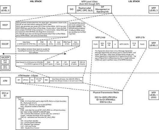
Based on Figure C-3, the following conclusions can be made regarding the ATM traffic and how ATM is used to carry MTP3 data:
The ATM layer uses the VPI and VCI fields to define multiple Virtual Channel Connections (VCC). Within each VCC, the PTI field is used to distinguish 1 type of traffic from another. A true ATM switch can support multiple VPI/VCI combinations. The EAGLE high-speed signaling link implementation needs to support only a single VPI/VCI combination.
The ATM stack contains built in fields that are used to check the integrity of the data that is received across the T1 connection. The ATM cell HEC field and the AAL5CP CRC-32 fields are used for data integrity.
MTP3 data (or MSUs) is transferred as User Data at the ATM cell level. A single MSU will require 1 or more ATM cells to transfer that MSU.
A significant amount of ATM protocol overhead is involved in transferring MSUs. The overhead includes:
ATM cell headers
AAL5CP layer pad bytes and trailer
SSCOP layer pad bytes and trailer
In addition to transferring MSUs, the ATM stack is capable of transferring
SSCOP Peer to Peer Messages - these are used primarily for connection setup and tear down and the acknowledgment of transferred data
SSCF Peer to Peer Messages - these are used primarily for high-speed signaling link alignment and proving
ATM Protocol Encapsulation
Two main types of data are delivered using ATM: SDUs and OAM cells. SDUs provide peer-to-peer information and user data (MSUs). OAM cells are used for operations and maintenance of the ATM connection. Figure C-4 provides the data encapsulation through the ATM stack. MTP3 is a user of SSCF and passes all PDUs directly to it.
Figure C-4 ATM Protocol Encapsulation

Payload Scrambling
Payload scrambling uses the x43+1 scrambling function.
Idle Cells
Idle cells uses the following 5-byte header format:
0x00 0x00 0x00 0x01 0x52.
The content of the information field shall be 0x6A repeated 48 times.
Since idle cells are transmitted on VPI=0, VCI=0, they are immediately discarded by the receiving end.
