11Using the Entity Relationship Designer
Using the Entity Relationship Designer
This chapter describes how to use the Entity Relationship Designer. It includes the following topics:
About the Entity Relationship Designer
The Entity Relationship Designer is a visual design tool that you can use to create an entity relationship diagram (ERD). You then map the entities and relationships in the diagram to objects in the Siebel repository, such as business components, links, joins, and so on. The Entity Relationship Designer includes the following capabilities:
An environment to create an ERD to relocate objects.
Various edit and layout options, such as aligning shapes, moving shapes, and modifying text.
The Entity Relationship Designer provides the following benefits:
Filters the list of objects that you choose when you bind entities and relations to Siebel objects. The list includes only the objects that support the context that the ERD represents. If no business components are suitable for binding, then you can open a wizard in the Entity Relationship Designer to assist you with creating a new business component.
Allows you to use the crows feet diagraming format to define relationships between entities.
Requires less work to define requirements for the data objects layer.
Improves your ability to trace configuration modifications back to data object layer requirements.
Creates a permanent record of entity relationship design in the Siebel repository.
Example of How the Entity Relationship Designer Filters Business Components
The following image describes an example entity relationship diagram that contains two entities and one relationship.
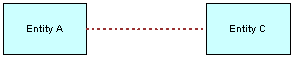
The following table describes the business components that are available to bind to Entity C. The business components that are available to bind depends on how the Entity Relationship Designer filters them.
Table Example of How the Entity Relationship Designer Filters Business Components
| Entity A | Relationship | Entity C | Business Components Available for Binding |
|---|---|---|---|
Unbound |
Any |
Unbound |
All business components are available for binding. |
Bound |
one-to-one |
Unbound |
A business component that contains a join to the primary table of the business component that is bound to Entity A is available for binding. |
Bound |
one-to-many |
Unbound |
The following business components are available for binding:
|
Bound |
many-to-one |
Unbound |
The following business components are available for binding:
|
Bound |
many-to-many |
Unbound |
A business component that is in the intersection of the one-to-many and many-to-one examples that this topic describes is available for binding. |
Example of How the Entity Relationship Designer Filters Links and Joins
Example of How the Entity Relationship Designer Filters Business Components describes an example ERD that includes two entities and one relationship. Assume you bind entities A and C to business components and that you must bind the relationship AC to a link or join. The Entity Relationship Designer filters the list of links and joins that are available for binding that the context described in the ERD requires.
The following table describes the links and joins that are available to bind to relationship AC.
Table Example of How the Entity Relationship Designer Filters Links and Joins
| Relationship AC | Objects That Are Available to Bind |
|---|---|
one-to-many |
The following objects are available to bind:
|
many-to-one |
The following objects are available to bind:
|
many-to-many |
A link between business components that are bound to Entities A and C is available to bind. |
Process of Creating and Binding an Entity Relationship Diagram
This task is a step in Roadmap for Configuring a Siebel Application.
To create and bind an ERD, perform the following tasks:
Two people are typically involved with creating and binding an ERD:
A business analyst defines an ERD that represents your business model because the analyst possesses knowledge about the business model.
A technical architect or developer binds the entities and relationships in the diagram to Siebel objects because the architect or developer possesses knowledge about the data objects layer.
Creating an Entity Relationship Diagram
This task is a step in Process of Creating and Binding an Entity Relationship Diagram.
An ERD can include business entities, entity properties, and the type of relationship that exists between entities, such as one-to-one, one-to-many, or many-to-many. Examples of common business entities include accounts, contacts, and addresses.
To create an entity relationship diagram
Open Siebel Tools.
Make sure object types for the Entity Relationship Designer are displayed.
For more information, see Displaying Object Types You Use to Configure Siebel CRM.
In the Object Explorer, click Entity Relationship Diagram.
In the Entity Relationship Diagrams list, right-click, and then click New Record.
Enter a name and associate a project to the new record.
The project must be locked to enter it in the Project field. For more information, see Using Siebel Tools.
Right-click, and then click Edit Entity Relationship Diagram.
Siebel Tools displays the canvas of the Entity Relationship Diagram.
Relocate an entity from the ERD Palette to the canvas.
Click the entity, and then enter a value in the Name property in the Properties window.
Repeatstep 7 through step 8 for the next entity in your diagram.
Relocate a relationship, such as ERD 1:1, from the pallet to the canvas.
Connect each end of the relationship to a connector point on one of the entities.
Before you connect two entities, place them on a horizontal plane, with the preceding entity placed first and the subsequent entity placed next. Place the entities in close proximity to one another. When you drop the relationship, Siebel Tools connects the start point and the end point of the relationship.
Repeat step 7 through step 11 until you added and connected all entities and relationships.
Binding an Entity to a Business Component
This task is a step in Process of Creating and Binding an Entity Relationship Diagram.
After you create an ERD that includes entities, you can bind an entity to a business component. If you bind an entity, then the Entity Relationship Designer filters the list of business components so that they fit the context of the ERD. For more information, see Example of How the Entity Relationship Designer Filters Business Components.
To bind an entity to a business component
In the Entity Relationship Designer, right-click an entity, and then click Bind Business Component.
In the Bind Business Component dialog box, choose the business component that you must bind to the entity.
If no business component meets your needs, then you can click New to start the New Business Component Wizard. For more information, see Configuring a Business Component.
After you click OK, Siebel Tools displays the name of the business component and the underlying base table in the entity.
Associating an Entity Attribute with a Business Component Field
This task is a step in Process of Creating and Binding an Entity Relationship Diagram.
After you bind an entity to a business component, you can associate an entity attribute with a business component field.
To associate an entity attribute with a business component field
In the Entity Relationship Designer, choose an entity that is bound to a business component.
Right-click in the Multi Value Property Window, and then click New Record.
In the Business Component field, click the arrow, and then choose a field.
Siebel Tools associates the attribute with the business component field. Note that the pick applet that displays if you click the arrow in the Business Component field is context-sensitive. It displays business component fields that Siebel CRM binds to the entity. If the entity is not bound to a business component, then Siebel Tools displays a set of default fields in the pick applet.
Binding a Relationship to a Link or Join
This task is a step in Process of Creating and Binding an Entity Relationship Diagram.
After you bind two entities to business components, you can bind the relationship between them. You can bind this relationship to a link or join. For more information, see Example of How the Entity Relationship Designer Filters Links and Joins, and About Links.
To bind a relationship to a link or join
In the Entity Relationship Designer, choose a relationship between entities.
Note that you must bind the two entities that the entity relationship joins before you can bind a relationship to a link or join.
Right-click, and then click Bind Entity Relation.
In the Bind Relationships dialog box, Siebel Tools displays the joins or links that exist between the two business components.
Choose the join or link that best represents the relationship that your ERD describes.
After you complete the bind, Siebel Tools bolds the relationship in the Entity Relationship Designer.
Opening or Modifying an Entity Relationship Diagram
This topic describes how to open or modify an Entity Relationship Diagram. It includes the following information:
Opening an Entity Relationship Diagram
You can open an entity relationship diagram.
To open an entity relationship diagram
In the Object Explorer, click Entity Relationship Diagram.
In the Entity Relationship Diagrams list, right-click the diagram you must open, and then click Edit Entity Relationship Diagram.
Viewing the Entities and Relations Lists of an ERD
You can toggle between the Entities List and the Relations List in the Object Explorer.
To view the entities or relations list of an ERD
To view the entities list, in the Object Explorer, expand the Entity Relationship Diagram tree, and then choose the Entity tree.
To view the relations list, in the Object Explorer, expand the Entity Relationship Diagram tree, and then choose the Entity Relation tree.
Modifying the Properties of a Relationship
You can use the Entity Relationship Diagrams list or the Properties window to modify the properties of a relationship. For example, you can modify the text that Siebel Tools displays at the end points of a relationship.
You cannot use the Entity Relationship Diagrams list or the Properties window to modify the type of relationship, such as modifying a one-to-one relationship to a one-to-many relationship. To modify the type of relationship, you delete the old relationship, and then move the new relationship from the ERD Palette to the canvas.
Using the Properties Window to Modify the Properties of a Relationship
You can use the Properties window to modify the properties of a relationship.
To use the Properties window to modify the properties of a relationship
Open an entity relationship diagram.
For more information, see Opening an Entity Relationship Diagram.
In the Entity Relationship Designer, choose the relationship you must modify.
In the Properties window, edit the property you must modify.
If you modify the value for the Name, End Name 1, or End Name 2 property, then Siebel Tools updates the labels in the diagram.
Using the Entity Relations List to Modify the Properties of a Relationship
You can use the Entity Relations list to modify the properties of a relationship.
To use the Entity Relations list to modify the properties of a relationship
In the Object Explorer, click Entity Relationship Diagram.
In the Entity Relationship Diagrams list, locate the entity relationship diagram you must modify.
In the Object Explorer, expand the Entity Relationship Diagram, and then click Entity Relations.
In the Entity Relations list, locate the record you must modify.
In the Properties window, edit the property you must modify.
If you modify the value for the Name, End Name 1, or End Name 2 property, then Siebel Tools updates the labels in the diagram.
Copying the Drawing of an Entity Relationship Diagram
You can copy the drawing of an ERD and paste it into a third-party application, such as Microsoft Word or Outlook. You cannot copy a drawing from one ERD and paste it into another ERD.
To copy the drawing of an entity relationship diagram
In the Entity Relationship Designer, right-click the canvas, click Copy, and then click Drawing.
In another application, such as Word or Outlook, choose Paste from the Edit menu.
Modifying Shapes and Lines in the Entity Relationship Designer
This topic describes how to modify the appearance of shapes and lines in the Entity Relationship Designer. It includes the following information:
Modifying Shapes in the Entity Relationship Designer
This topic describes how to modify shapes in the Entity Relationship Designer. You perform all tasks that this topic describes in the Entity Relationship Designer.
To modify shapes in the Entity Relationship Designer
To modify the appearance of a shape in an ERD:
Choose an entity or relationship.
Right-click, and then click Shape Properties.
Modify the properties in the Item Properties dialog box, and then click OK.
To choose multiple objects in an ERD:
Choose an entity.
Hold down the shift key.
With the shift key still depressed, click another entity.
Release the shift key.
To align shapes relative to each other:
Choose multiple objects in the Entity Relationship Designer.
For more information, see the following.
Right-click the canvas, click Layout, Align, and then click one of the following menu items:
Lefts
Centers
Rights
To make shapes the same size:
Choose multiple objects in the Entity Relationship Designer.
For more information, see Modifying Shapes in the Entity Relationship Designer.
Right-click the canvas, click Layout, Make Same Size, and then click one of the following menu items:
Width
Height
Both
Modifying Relationships in the Entity Relationship Designer
This topic describes how to modify relationships in the Entity Relationship Designer. You perform all tasks that this topic describes in the Entity Relationship Designer.
To modify relationships in the Entity Relationship Designer
To add a point to a relationship:
Right-click a relationship, click Edit, and then click Add Point.
Grab the point, and then move it to a new position on the canvas.
You can modify the shape of a relationship. For example, you can add a ninety degree angle. This configuration helps to avoid overlapping lines in a complex diagram.
To hide the text labels of a relationship, right-click a relationship, click Edit, and then click Hide Text.
You can hide the text label of a relationship, including the Relationship Name, End Name 1, and End Name 2.
To move the name of a relationship, right-click a relationship, click Edit, and then click Move Text Back or Move Text Forward.
You can modify where Siebel Tools displays the text label for the name of a relationship. Note that you cannot modify the location of the text labels for the End Name 1 and End Name 2 properties.
To return text labels of a relationship to the default setting, right-click a relationship, click Edit, and then click Move Text to Default.
To display a connection point, right-click the canvas, and then click Connection Points.
To hide connection points, choose Connection Points again to remove the check mark.
A connection point is the point on an entity where the relationship connects. You can display or hide a connection point. For example, you can display connection points when you create an ERD, and then hide them when you print an ERD.
Moving Shapes in the Entity Relationship Designer
To move a shape in the Entity Relationship Designer canvas, you can relocate it or use the menu items in the Layout menu.
To move shapes in the Entity Relationship Designer
In the Entity Relationship Designer, do one of the following:
Move the shape to another position on the canvas.
Right-click the shape, click Layout, Move, and then click one of the menu items described in the following table.
Menu item Description Left by 1
Moves the shape in the direction you choose by 1 pixel.
Right by 1
Up by 1
Down by 1
Left by X
Moves the shape in the direction you choose according to the number of pixels that one cell on the canvas contains. The number of pixels can vary depending on the resolution setting of your monitor.
Right by X
Up by X
Down by X
You can use the shortcut keys that Siebel Tools displays in the Move submenu of the Layout menu.
Resizing Shapes in the Entity Relationship Designer
To resize a shape, you can move it in the canvas or use the Resize menu item in the Layout menu.
To resize shapes in the Entity Relationship Designer
In the Entity Relationship Designer, choose the shape you must resize.
Do one of the following:
Click one of the connection points on the entity, and then move it to a new position.
Right-click the entity, click Layout, Resize, and then click one of the menu items described in the following table.
Menu item Description Height by 1
Resizes the dimension you choose by 1 pixel.
Height by -1
Width by 1
Width by -1
Height by X
Resizes the dimension you choose according to the number of pixels that one cell of the canvas contains. The number of pixels can vary depending on the resolution setting of your monitor.
Height by -X
Width by X
Width by -X
You can use the shortcut keys in the Expand submenu of the Layout menu.
Zooming, Displaying, and Snapping the Grid
You can zoom, display the grid, or snap an object to the grid in the Entity Relationship Designer.
To zoom, display, and snap the grid
To zoom in the Entity Relationship Designer, right-click the canvas, click Zoom, and then click one of the following menu items:
Zoom In.
Zoom Out.
Choose a percentage.
You can choose a default zoom amount or enter a percentage to zoom in and out of an ERD.
To display the grid, right-click the canvas, and then click Show Grid.
To hide the grid, click Show Grid again, which removes the check mark.
The grid helps you align entities and relationships in an ERD. It is useful to display the grid when you work in the canvas, and then hide it when you print the ERD.
To turn on the Snap to Grid feature, right-click the canvas, and then click Snap to Grid.
The Snap to Grid feature helps you keep entities and relationships aligned while you define your ERD.