IP Connections
IP connections involve the following assignments:
- Transport protocol – The SCTP transport protocol is specified by the
ent-assocandchg-assoccommands. - Adapter protocol – The M3UA, M2PA, or SUA adapter protocol is specified by the
adapterparameter of theent-assocandchg-assoccommands. - One or two near-end (local) hosts – The local host is specified by the
lhostparameter of theent-assocandchg-assoccommands. A second local host can be specified for an association using thealhostparameter of theent-assocandchg-assoccommands, allowing the near-end host of the association to be multi-homed. Specifying only one local host for an association allows the association to be uni-homed. - Far-end (remote) host – The remote host is specified by the
rhostparameter of theent-assocandchg-assoccommands. - Near-end (local) transport protocol port – The local transport protocol port is specified by the
lportparameter of theent-assocandchg-assoccommands. - Far-end (remote) transport protocol port – The remote transport protocol port is specified by the
rportparameter of theent-assocandchg-assoccommands. - SS7 signaling link – specified by the
locandlinkparameters of theent-slkcommand.
The local host is mapped to a particular Ethernet interface on the IP card by
linking the local host name of the IP connection to an IP address with the ent-ip-host command. The IP address is also assigned to an IP card and to an Ethernet
interface on that IP card using the chg-ip-lnk command. A
signaling link on that card is assigned to the IP connection using the link parameter of the ent-assoc
and chg-assoc commands and referencing the signaling link
on the IP card.
An SCTP association can establish a connection between one local host and one remote host (a uni-homed association) or between multiple local hosts and a remote host (a multi-homed association). It is possible that the remote host may be multi-homed, but the EAGLE allows only one remote host to be specified for a multi-homed association. If an IP node has multiple IP address associated with it, then an SCTP association originating from this node may take advantage of this added connectivity by establishing an SCTP multi-homed association.
For more information on multi-homed associations, see the Multi-Homed SCTP Associations section and the Routing section.
Figure 2-1 shows the components of an SCTP association and how these components interact with each other.
Figure 2-1 SCTP Association Database Relationships

There is no direct correlation between signaling link ports and Ethernet interfaces. A card can be using Ethernet interface A and signaling link B to transmit data to the remote host. Another scenario could have the card using Ethernet interface B and signaling link A to transmit data to the remote host.
The numbers of signaling link ports and Ethernet interfaces on IP cards varies depending on the card type and application running on the card, as shown in Table 2-1. The sections that follow Table 2-1 describe the IP connections supported by each IP card type. The IP connections described in these sections are uni-homed SCTP associations.
Table 2-1 Ethernet Interface and Signaling Link Combinations
| Card | Application | Ethernet Interface | Signaling Link |
|---|---|---|---|
|
E5-ENET |
IPLIMx |
A and B |
A - A7, B - B7 |
|
IPGWx |
A and B |
A |
IP Connection on an E5-ENET Card Running the IPGWx Application
Figure 2-2 IP Connections using an E5-ENET Card running the IPGWx Applications

The assignment of the transport protocol port number is made through the local host
port (lport) and remote host port (rport) parameters of the ent-assoc or chg-assoc commands (for an SCTP association).
Figure 2-3 shows typical IP connection data for a uni-homed SCTP association and how these components interact with each other.
Figure 2-3 Typical SCTP Association Configuration

The IP connection defined by the SCTP association is from local host ipnode-1204 (190.50.1.139), SCTP port 2048, to remote host remote-node-2 (190.50.1.144), SCTP port 3529, using Ethernet interface B on IP card 1204, and signaling link A on IP card 1204.
IP Connection on an E5-ENET Card Running the IPLIMx Application
E5-ENET cards running the IPLIMx applications can have 16 signaling links (A, B, A1, B1, A2, B2, A3, B3, A4, B4, A5, B5, A6, B6, A7 or B7) and 2 Ethernet interfaces (A or B) resulting in a maximum of 16 IP connections, one for each signaling link. Each link can use either Ethernet interface A or B. The local host and alternate host assigned to a signaling link must use different Ethernet interfaces; they cannot be assigned to the same Ethernet interface. Figure 2-4 shows some ways the 16 signaling links and the 2 Ethernet interfaces can be used to establish IP connections.
Figure 2-4 IP Connections using E5-ENET Cards running the IPLIMx Applications

Multi-Homed SCTP Associations
If the IP cards are EDCMs or E5-ENET cards, SCTP
associations can have two local hosts, and are referred to as multi-homed associations. A
multi-homed association uses both Ethernet interfaces on the IP card. Each Ethernet interface is
assigned to a local host. Each local host is assigned to a different local network. One of the
local hosts is configured with the lhost parameter of the
ent-assoc or chg-assoc commands.
The second local host, or alternate local host, is configured with the alhost parameter of the ent-assoc or chg-assoc commands. One of the local hosts references one of the Ethernet
interfaces on the IP card and the other local host references the other Ethernet interface on the
IP card. The multi-homed SCTP association allows the E5-ENET card to communicate with another
node over two networks. Traffic is passed to and from the remote node on either local interface
on the card.
An SCTP association can be uni-homed also. A uni-homed association uses only one
Ethernet interface (A or B), which is assigned to only one local host. This local host is
configured with the lhost parameter of the ent-assoc or chg-assoc commands. For a uni-homed
association, the alhost parameter is not be specified with the
ent-assoc or chg-assoc commands.
A uni-homed association allows the IP card to communicate to another node on one network only.
Traffic is passed to and from the remote node on the local interface on the card defined by the
lhost parameter.
The remote node can be either uni-homed or multi-homed, and is not dependent on whether or not the local node (containing the local hosts) is uni-homed or multi-homed. For example, Node A can be uni-homed and can be connected to a multi-homed Node B, or a multi-homed Node A can be connected to a uni-homed Node B. Table 2-2 illustrates the possible combinations.
Table 2-2 Uni-Homed and Multi-Homed Node Combinations
| Node A | Node B |
|---|---|
|
Uni-homed |
Uni-homed |
|
Uni-homed |
Multi-homed |
|
Multi-homed |
Uni-homed |
|
Multi-homed |
Multi-homed |
Multi-Homed Associations on EDCMs or E5-ENET Cards Running the IPLIMx Application
A multi-homed association on an IPLIMx card uses both Ethernet interfaces to reach the remote host, but only one signaling link. An association, either uni-homed or multi-homed, can be assigned to only one signaling link. That signaling link can be either signaling link A or B. The local and alternate local hosts are assigned to each Ethernet interface on the IP card. The IPLIMx cards are limited to one IP connection per signaling link. Since the IPLIMx cards can have eight signaling links on the card, eight multi-homed associations can be assigned to an IPLIMx card.
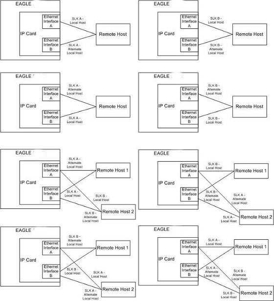
Figure 2-5 shows the ways a multi-homed IP connection can be established on an IPLIMx card. The remote hosts can be multi-homed, but only one remote host can be specified for each multi-homed association in the EAGLE, so only one remote host is shown in Figure 2-5.
Figure 2-5 Multi-Homed Associations on E5-ENET Cards running the IPLIMx Applications
Multi-Homed Associations on E5-ENET Cards Running the IPGWx Applications
A multi-homed association on an IPGWx card uses both Ethernet interfaces to reach the remote host, but only one signaling link, signaling link A on the IPGWx card. The local and alternate local hosts are assigned to each Ethernet interface on the IP card. The IPGWx cards can have up to 50 connections for each IPGWx card. The IPGWx card can contain both uni-homed and multi-homed IP connections, as long as the total number of connections does not exceed 50.
Figure 2-6 shows the way a multi-homed IP connection can be established on an IPGWx card. The remote hosts can be multi-homed, but only one remote host can be specified for each multi-homed association in the EAGLE, so only one remote host is shown in Figure 2-6.
Figure 2-6 Multi-Homed Associations on E5-ENET Cards running the IPGWx Applications
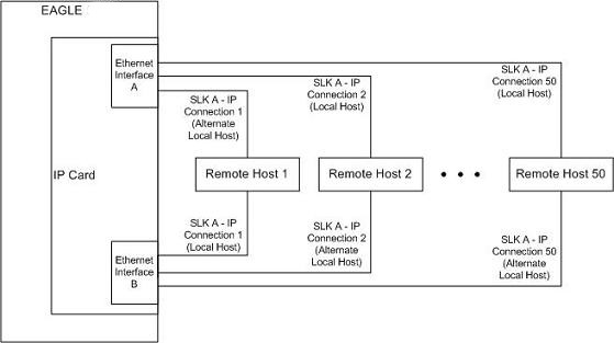
Figure 2-7 shows the components of the multi-homed SCTP association and how these components interact with each other.
Figure 2-7 Multi-Homed Association Database Relationships
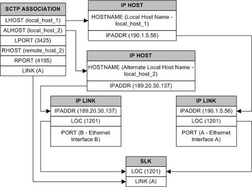
Using the data shown in Figure 2-7, the IP connection is defined as a multi-homed association, connecting to a remote host using local hosts 190.1.5.56 and 189.20.30.137 over SCTP port 3425, using signaling link B on card 1201.
Routing
The IP7 Secure Gateway functionality in the EAGLE support two transport protocols –TCP and SCTP. Although both transport protocols are connection oriented, they differ greatly with respect to operation in a multi-homed host environment. The TCP protocol provides for a point-to-point transport connection. The SCTP protocol implements connections with either point to point, point to multi-point, or multi-point to multi-point connectivity capabilities.
An SCTP IETF connection ( association) is defined as a four-tuple as follows:
- local host list – one or more of the local host’s IP interface addresses
- local SCTP port
- remote host list – one or more of the remote host’s IP interface addresses
- remote SCTP port
Based on this definition for an SCTP IETF connection, and the fact that the IPGWx and IPLIMx applications may utilize both Ethernet interfaces (a multi-homed host), an SCTP IETF association can take advantage of multi-homing and be a multi-homed SCTP endpoint. As a multi-homed endpoint, an SCTP IETF connection remains active and usable as long as at least one of the Ethernet interfaces can be reached by the remote host. Multiple paths through multiple interfaces to the remote host provides a more reliable connection. The SCTP IETF protocol is designed to make such a network outage transparent to the application.
In previous releases, an SCTP IETF endpoint could only operate as a uni-homed host using only the Ethernet A interface. In this mode, any SCTP transmission received on or transmitted out of the Ethernet B interface are silently discarded. By using the Ethernet B interface, the SCTP protocol running on the IP card can provide SCTP multi-homing endpoint support – that is, when an SCTP IETF association is formed, it may list both the Ethernet A and B IP addresses for the respective interfaces. As a multi-homed association endpoint, SCTP data would be allowed to flow on either of the Ethernet interfaces and thus provide more robust network connectivity.
In order to provide more flexible network connectivity, an association can be configured as follows with respect to the Ethernet interfaces:
- Ethernet A interface only (uni-homed)
- Ethernet B interface only (uni-homed)
- Ethernet A and B interface (multi-homed)
The interface mode is specified by the lhost and alhost parameters of the ent-assoc or chg-assoc commands.
In previous releases, the lhost parameter of the
ent-assoc or chg-assoc commands
is used to define the local IP address of the SCTP IETF association endpoint. The IP address
would have to be an IP address associated with an Ethernet A interface. With this release, the IP
address may be associated with either the Ethernet A or B interfaces. If it is an Ethernet A
interface IP address, and the alhost parameter is not specified,
then the association operates as a uni-homed SCTP endpoint on Ethernet interface A. If it is an
Ethernet B interface IP address, and the alhost parameter is not
specified, then the association operates as a uni-homed SCTP endpoint on Ethernet interface B. An
association is configured as an SCTP multi-homed endpoint by specifying both the lhost and alhost parameter values with
values corresponding to the Ethernet interface IP address for the IP card. The lhost and alhost parameter values
represent the IP addresses specified by the chg-ip-lnk command
for the specific IP card. Traffic cannot be passed between the Ethernet interfaces on the IP card
containing a multi-homed SCTP association. The IP card cannot act as an IP router between the
networks defined by the local host and alternate local hosts of a multi-homed association.
A host that is not on the local network, the network identified by the local host’s
IP address, can be reached only through a gateway router. A gateway router is a device with more
than one physical network connection, and can be connected to multiple networks. Unlike a
multi-homed host, a gateway router is permitted to route IP messages between the physical
Ethernet interfaces on the IP card. The network portion of the gateway router’s IP address must
be the same as the network portion of the IP address of one of the IP addresses of the Ethernet
interfaces on the IP card. The gateway router is configured using the defrouter of the chg-ip-card command, or using the
ent-ip-rte command.
Static entries are added to the IP Routing table using the ent-ip-rte command. Static routes are usually assigned to give control over which
routers are used, allowing different routers to be selected based upon the destination IP
address. There are two types of static routes:
- host static IP routes
- network or subnetwork static IP routes
The default route entry is a special static route. If there is not a specific host or network address in the IP Routing table that matches the destination IP address of an outbound datagram, then the datagram is sent to the default router (gateway) specified by the default route.
An IP route is configured using the ent-ip-rte
command with the location of the IP card, the IP address of the gateway router (the gtwy parameter), and the IP address and subnet mask of the destination
(that is, host or network). The IP address of the gateway router must be a locally attached IP
address (that is, the gateway IP address must share the network portion of one of the two
Ethernet interfaces).
When an IP packet is to be transmitted the IP routing table must be interrogated to determine where to send the IP datagram. If the destination IP address is local to the node (that is, directly reachable by an Ethernet interface), then the IP datagram is transmitted directly to the node with that associated IP address. If the destination IP address is determined to not be local to the node, then it must be routed (that is, sent to a gateway to reach its destination).
IP routing requires accessing the IP routing table to select a route. The destination IP address of the outbound datagram is used to search the IP routing table for the most specific route match. The order for selection is:
- Host route
- Subnetwork route
- Network route
- Aggregated route
- Default route
Based on this selection order if an IP route is found then the outbound IP datagram will be transmitted to the gateway specified by the route. If no IP route is found (where no default route is specified), then the transmission of the datagram fails due to destination unreachable.
The capability to enter static IP routes provides for flexibility and control with respect to controlling network traffic. An IP card can contain up to 64 IP routes. The EAGLE can contain up to 1024 IP routes.