| Oracle® Communications EAGLE Database Administration - SS7 User's Guide Release 46.7 E97335 Revision 1 |
|

 Previous |
 Next |
| Oracle® Communications EAGLE Database Administration - SS7 User's Guide Release 46.7 E97335 Revision 1 |
|
|
Previous |
Next |
The ITU SLS Enhancement gives customers the ability to modify the method the EAGLE distributes traffic across SS7 links.
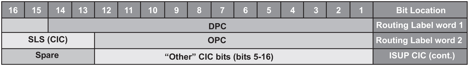
The EAGLE uses the least significant bit of the SLS to load share between linksets of a combined linkset. ITU ISUP messages use a SLS that is obtained from the lower 4 bits of the CIC field representing the circuit being used. Figure 3-2 shows the ITU ISUP routing label with the CIC field.
Figure 3-2 ITU ISUP Routing Label with CIC
CIC selection can be determined based on an odd or even method where a SSP uses either all odd CICs, or all even CICs, to help prevent “glaring” (that is, 2 SSPs attempting to seize the same trunk at the same time). This causes the least significant bit of the SLS to be fixed. If the least significant bit is fixed, inadequate load sharing occurs for the SS7 network. This situation can also occur within a single linkset (international), since the EAGLE also uses the lower 4 bits of the SLS (containing a fixed least significant bit) to select a link within a linkset.
This enhancement provides the user three options for addressing the problem:
slsrsb parameter of either the ent-ls or chg-ls commands. This action takes place on the outgoing linkset. More information on this option can be found in Bit Rotation.slsocbit parameter of either the ent-ls or chg-ls commands. More information on this option can be found in Use of the Other CIC Bit.Before the Use of the Other CIC Bit option can be set, the Other CIC Bit Used feature must be turned on with the chg-feat command and the slsocb=on parameter. This can be verified with the SLSOCB = on entry of the rtrv-feat command output.
The slsrsb and slsocbit parameters can only be specified for linksets that contain either an ITU international or ITU national adjacent point code (either a 14-bit or 24-bit ITU-N adjacent point code).
The value of the slsrsb and slsocbit parameters are only displayed in the rtrv-ls command output when a specific linkset is being displayed with the rtrv-ls:lsn=<linkset name> command.
Note:
When two linksets are used as a combined linkset, both linksets should use the sameslsrsb and slsocbit values.Note:
If therandsls parameter of the chg-stpopts command, a system-wide option, is set to either all or class0, the EAGLE uses the Random SLS Generation feature to perform load sharing between ITU linksets. The slsrsb parameter value is ignored. However, the ent-ls and chg-ls commands allow the slsrsb parameter value to be specified. For more information on the Random SLS Generation feature, refer to Configuring the System for Random SLS Generation.islsrsb parameter of either the ent-ls or chg-ls commands. More information on this option can be found in Incoming Bit Rotation.Only the link selection algorithm is modified by this feature, not the actual SLS field of the message (that is, the SLS value received by the EAGLE is the SLS value sent by the EAGLE).
Bit Rotation
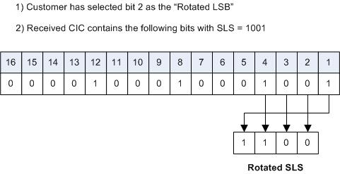
To alleviate the situation of the EAGLE selecting the same linkset of a combined linkset, the customer can apply the bit rotation option. Bit rotation can be used, on a per linkset basis, to ensure the EAGLE does not use the static least significant bit (always 0 or always 1) in the received SLS for linkset selection.
When defining a link set using the ent-ls or chg-ls commands, the customer will be able to select which bit (1-4) of the SLS field to use as the least significant bit for link set selection. This rotation only affects the 4 bits of the SLS during linkset selection, as follows:
For example: SLS = 0110 becomes Rotated SLS = 1100. SLS = 1011 becomes Rotated SLS = 0111
For example: SLS = 0110 becomes Rotated SLS = 1001. SLS = 1011 becomes Rotated SLS = 1110
For example: SLS = 0110 becomes Rotated SLS = 0011. SLS = 1011 becomes Rotated SLS = 1101
Figure 3-3 shows an example of bit rotation.
Figure 3-3 Example of Bit Rotation
After the SLS is rotated, the existing algorithm for selecting a linkset and signaling link is performed, and the message is sent out the selected link. Note that the SLS is modified only for the link selection algorithm, and is not modified in the outgoing message.
Use of bit rotation alone does not guarantee an even distribution of ITU-ISUP messages across all links within a linkset. The EAGLE uses all 4 bits of the SLS to determine the actual link to route messages. Since the static bit is simply rotated within the SLS, all possible values of the SLS field will still not be realized. A second option, Use of the Other CIC Bit, must be applied to guarantee even distribution across all links within the linkset.
Use of the Other CIC Bit
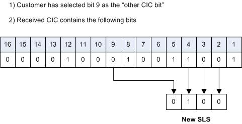
The Use of the Other CIC Bit option can be applied by the customer to alleviate the problem of the EAGLE not load sharing between all links within a linkset. When defining a linkset with the chg-ls or ent-ls command, the user can specify whether the Use of the Other CIC Bit option is to be used during link selection. If the option is to be used, the customer can also specify which bit (bits 5 through 16 of CIC) is to be used as the “other CIC bit”.
During link selection, the specified bit acts as the most significant bit of the new SLS, and bits 2 through 4 of the received CIC become the least significant bits of the new SLS.
Figure 3-4 shows how the new SLS field is generated using the “other CIC bit.”
Figure 3-4 SLS creation Using “Other CIC Bit”
After the SLS is generated using the “other CIC bit”, the existing algorithm for selecting a linkset and signaling link is performed, and the message is sent out from the selected link. Note that the SLS is modified only for the link selection algorithm, and is not modified in the outgoing message.
Incoming Bit Rotation
Incoming Bit Rotation is set on the incoming linkset, where the existing SLS bit rotation option is set on the outgoing linkset. The algorithm used for rotating the SLS bits on outgoing linksets is also used on incoming linksets. This method provides additional capability to fairly distribute traffic across links and linksets, however it still does not guarantee an even distribution of messages for all set of input SLS values. Rotating SLS Bits on outgoing linksets is supported only for ITU linksets. Rotating SLS bits on incoming linksets is supported for ANSI and ITU linksets. For ITU linksets, the SLS value is only four bits and all four bits are considered for bit rotation. Table 3-4 shows examples of bit rotation for ITU linksets.
Table 3-4 ITU SLS Bit Rotation
| Incoming ITU SLS Value | Least Significant Bit Being Rotated | Rotated SLS Value |
|---|---|---|
| 0110 | 2 | 0011 |
| 1110 | 3 | 1011 |
| 0010 | 1 | 0010 |
| 1101 | 4 | 1011 |
For ANSI linksets, which may have a five or eight bit SLS value, the full five or eight bits are considered for link and linkset selection. Table 3-5 shows the rules that apply to rotating the SLS bit value in an ANSI linkset.
Table 3-5 ANSI Linkset Incoming Bit Rotation Rules
| Rule | Incoming Linkset ASL8 Value | Incoming Linkset RSLS8 Value | ISLSRSB Values | SLSCNV/ Outgoing Linkset SLSCI Value | Incoming SLS Bit Rotation (ISLSBR) |
|---|---|---|---|---|---|
| 1 | No | No | 1 - 5 | No | The least significant 5 bits of the SLS are considered for rotation. |
| 2 | No | No | 1 - 5 | Yes | The least significant 5 bits of the SLS are considered for rotation. |
| 3 | No | Yes | 1 - 8 | No | No incoming SLS bit rotation is performed. The 5-Bit to 8-Bit SLS Conversion feature must be turned on to perform incoming SLS bit rotation. |
| 4 | No | Yes | 1 - 8 | Yes | The 8 bit SLS value is obtained after the 5-bit to 8-bit SLS conversion is performed is considered for rotation. |
| 5 | Yes | No | 1 - 5 | N/A | The least significant 5 bits of the SLS are considered for rotation. |
| 6 | Yes | Yes | 1 - 8 | N/A | The 8-bit SLS value is considered for rotation. |
Rotating the SLS bits on ANSI linksets is based on the combination of the ASL8, RSLS8, SLSCNV/SLSCI, and ISLSRSB parameter values.
The ASL8 parameter value for the incoming linkset specifies whether the adjacent node is sending messages with a 5-bit SLS or an 8-bit SLS.
If the ASL8 parameter value for the incoming linkset is No, and the global SLSCNV/SLSCI parameter value for the outgoing linkset is Yes, the 5-Bit to 8-Bit SLS Conversion feature is applied to the incoming 5-bit SLS value.
The RSLS8 parameter value for the incoming linkset specifies the number of SLS bits to be considered for rotation. If the RSLS8 value is Yes, 8 bits are considered for rotation. If the RSLS8 value is No, the least significant 5 bits of the SLS are considered for rotation. If the ASL8 value is No, the RSLS8 value is Yes, and the STPCNV/SLSCI value is No, then no rotation is performed. See Table 3-6.
Table 3-6 ANSI SLS Bit Rotation
| Incoming ANSI SLS | Incoming Linkset RSLS8 Value | Least Significant Bit Being Rotated | Outgoing ANSI SLS | Rotated SLS | Rule Applied |
|---|---|---|---|---|---|
| 11000110 | No | Bit 2 | 11000110 | 11000011 | 5 |
| 01011110 | Yes | Bit 7 | 01011110 | 01111001 | 6 |
| 10010 | No | Bit 4 | 10110010 | 10101010 | 2 |
| 10010 | Yes | Bit 8 | 10110010 | 01100101 | 4 |
| 01101 | No | Bit 4 | 01101 | 10101 | 1 |
| 01101 | Yes | Bit 7 | 01101 | No Rotation | 3 |
The new SLS value created after the SLS bits have been rotated is used for linkset and signaling link selection.
Combining the Bit Rotation, Use of the Other CIC Bit, Incoming Bit Rotation, and Random SLS Options
on, then an 8-bit random SLS value is generated.on, the randomly generated SLS value is replaced. Go to step 5. on, the 5-bit ANSI SLS value is converted to an 8-bit SLS value using the 5-Bit to 8-bit SLS Conversion feature.lst=c), the SLS value is modified using the standard fifth bit rotation, replaced in the MSU, and sent to the selected signaling link.