This chapter helps to configure and manage the External Data Descriptors and Connectors.
Topics:
External Data Descriptors (EDD) are definitions of specific data content from External Data Sources (EDS). Each EDS may have a number of EDDs defined against it. EDD definitions can be used for ingesting data into OFSAA Data Foundation or extracting data from it.
DIH also supports the usage of control information while ingesting data into the Data Foundation. Such control information may also be defined as EDDs.
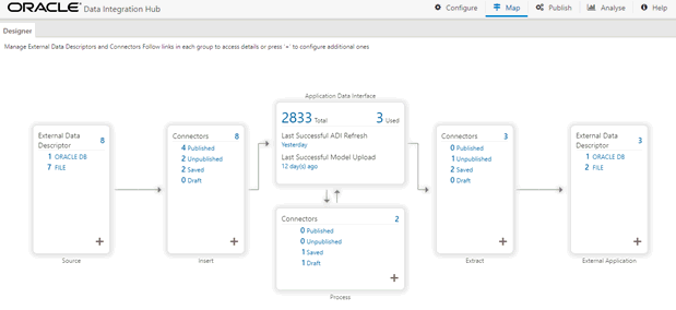
1. From the Data Integration Hub Designer window, to manage External Data Descriptors, click links in each group to access details.
Figure 19: DIH Designer Window

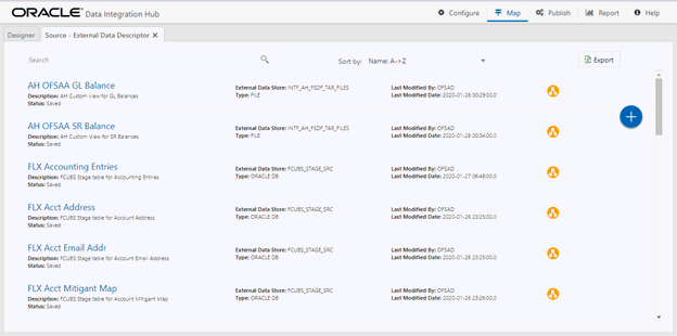
2. To manage Source – External Data Descriptor, click the links under Source.
Figure 20: Source – External Data Descriptor

The Source - External Data Descriptor window is displayed.
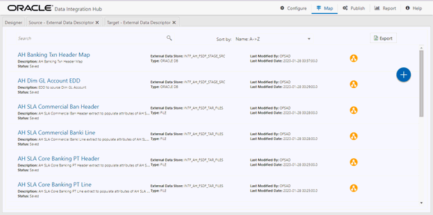
3. To manage Target – External Data Descriptor, click the links under External Application.
Figure 21: Target – External Data Descriptor

The Target - External Data Descriptor window is displayed.
4. From the Data Integration Hub Designer window, click  Source
or Target EDD windows. to configure additional
EDDs or click Add
  from
the Source or External Application.
5. For more information, see Defining an External Data Descriptor.
6. Click Export. The List of EDDs are exported to an Excel sheet with the following information:
a. EDD IDs
b. EDD Name
c. Description
d. EDS Name
e. EDS Type
f. Status
g. Last Modified By and
h. Last Modified Date
The following sections describe the fields in the External Data Descriptor window.
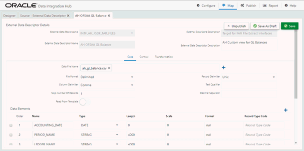
The following table describes the fields in the Data tab.
Fields |
Description Fields marked in red asterisk (*) are mandatory |
|---|---|
Data File Name |
You can add multiple data files to an EDD. For example, you need to add the Term Deposits Contracts data file. There are Term Deposits Contracts data files for Retail as well as Corporate accounts. Therefore, to get both these details, you first add the Term Deposits Contracts data file for Retail accounts, such as td_contracts%#MISDATE%_1.csv, and as the next record, add Term Deposits Contracts data file for Corporate accounts. Example: td_contracts%#MISDATE%_1.csv |
Record Delimiter |
The records are stored differently in different operating systems. The options available are: · MS-DOS · Unix · No Record Delimiter · Other For example, select Unix. |
File Format |
There are two options: · Fixed Length: The file has records and columns with a fixed length. Each column has a predetermined and unchanging size, set when the record layout is designed, and the sum of the column sizes add up to the record size. · Delimited: There is a separation of the records and columns using a delimiter character like a comma, semicolon, hyphen, and so on. For example, select Delimited. |
Text Qualifier |
A character that identifies a text. This is used when some characters exist within a text. Generally, double quotes are used, prefixed, and suffixed with text. This is optional. |
Skip Number Of Records |
Provide the number of records to be skipped. The records are skipped from the top. Generally, this is used to skip Headers. |
Decimal Separator |
This mentions up to which decimal digit you want to view the result. |
Read from template |
A
template contains all the values and is in Excel file format.
If the template is not available, you must create it manually
by clicking Add You can also drop the template in the area “Drop template here or click to select “. |
Select Template (*.xls,*.xlsx,*.CSV Files Only |
Click Browse and select the required template. |
Data Elements
|
|
Name |
Name of the field in EDD. Example: Field name in a file or column name in a table. NOTE: The Field name of XML type must not be more than 25 characters and for others must not be more than 30 characters. |
Type |
This shows the Data type of the field. Example: String, Number, EBCDIC, and so on. |
Length |
This is applicable only for the EBCDIC format. This is the length of the EBCDIC data type. In the case of a file, it is length only. |
Precision |
This is used to specify the decimal point. Example: 10.3. |
Format |
Specify the format for columns of type date here. If left blank, a default format of DD/MM/YYYY is assumed and used. NOTE: · The default format is fixed and does not change with database or system language settings. · For data ingestion, enter the format in which date fields are provided. · For data extraction, enter the format in which extracted date fields must be recorded. For example, in the file extract, to represent the date, 31st January 2020, as “31/01/2020”, specify the format as DD/MM/YYYY for the date columns. |
Record Type Code |
This identifies the Record type in a file where Header, Trailer, and Data are of different record length and type. The values can be any string available in the text file. This value is only possible for the first field in a file. Example: The values can be DATA; CTRL to specify it is a control record. |
In the Control tab, DIH enables you to:
1. Reconcile between source data received and data loaded into OFSAA, using the control information available from the source system. This feature is used to implement record count validation or amount reconciliation from a source file. It also allows specifying a threshold for validation. The specified threshold is compared with the difference (record count or amount) to perform the validation. Only in case, the difference is more than the threshold value the execution fails. A detailed report on control information from both source and the final data loaded along with threshold breach is available in Execution History.
2. The threshold can be absolute or percentage value. The connector execution process considers the threshold type while performing reconciliation.
3. Generate control information for File extracts from OFSAA. Specifying control for extract EDDs generates control details, based on the configuration in the EDD. Both record count and amount value (sum, average, max, and so on) for specific columns are recorded into the control file.
NOTE:
This option is applicable only for File type EDDs (ASCII and EBCDIC).
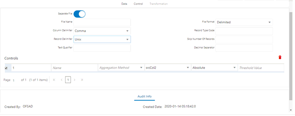
The following fields must be configured to achieve this functionality.
Fields |
Description Fields marked in red asterisk(*) are mandatory |
|---|---|
When Separate File is selected as Yes. |
|
File Name |
Specify the name of the file. |
File Format |
There are two options: · Fixed Length: The file has records and columns with a fixed length. Each column has a predetermined and unchanging size, set when the record layout is designed, and the sum of the column sizes add up to the record size. · Delimited: There is a separation of the records and columns using a delimiter character like a comma, semicolon, hyphen, and so on. In the previous example, select Delimited. |
Column Delimiter |
If the File Format is selected as Fixed Length, the Column Delimiter would by default be Other. If the File format is selected as Delimited, the following options are available in the drop-down list. · Other · Space · Semicolon · Comma · Tab In the previous example, select Comma. |
Record Type Code |
Used to uniquely identify a record within a file. A Financial Institution sometimes provides files that have data and control records within the same file. In that case, to distinguish between data record and control record, the first field is Record Type. It has a specific value to identify that. Here, specify the value that identifies the Data. Values can be ‘DATA’ and so on. For the Control record, the value is specified under the Control tab. Only the first field of a file is used for Record Type. |
Record Delimiter |
The records are stored differently in different operating systems. The following options are available: · MS-DOS · Unix · No Record Delimiter · Other For example, select Unix. |
Skip number of records |
Provide the number of records to be skipped. The records are skipped from the top. Generally, this is used to skip Headers. |
Text Qualifier |
A character that identifies a text. This is used when some characters exist within a text. Generally, double quotes are used, prefixed, and suffixed with text. This is optional. |
Decimal separator |
Specify up to which decimal digit you want to view the result. |
Record Type Length |
The length of the record type value to pick up the correct record. For example, if the control record is “DATATotal Records400” and DATA is the Record type, the length is ‘4’. This is applicable only for Control records that are of Fixed length. |
Control Name Length |
Based on the previous example, the Control name is “Total Records”. Hence, the Control Name Length is ‘13’. |
Control Value Length |
Based on the previous example, the Control value is 400. Hence, the length of the control value is ‘3’. |
When Separate File is selected as No. |
|
Record Type Code |
Used to uniquely identify a record within a file. A Financial Institution sometimes provides files that have data and control records within the same file. In that case, to distinguish between data record and control record, the first field is Record Type. It has a specific value to identify that. Here, specify the value that identifies the Data. Values can be ‘DATA’ and so on. For the Control record, the value is specified under the Control tab. Only the first field of a file is used for Record Type. |
Control Value Length |
Based on the previous example, the Control value is 400. Hence, the length of the control value is ‘3’ |
Control Name Length |
Based on the previous example, the Control name is “Total Records”. Hence, the Control Name Length is ‘13’. |
Controls |
|
Control Name |
Specify the name of the control. |
Aggregation Method |
Select either Aggregation Method or Count. The supported aggregation methods are as follows: · Min · Max · Average · Sum |
Aggregation Column Name |
Select the column on which the aggregation method is applied. NOTE: For count, no column needs to be selected. |
Threshold Type |
This field is optional. There are two selections of threshold, percentage, or absolute. If the percentage is selected, the reconciliation difference in percent is matched against this threshold value. If absolute is selected, the absolute percent difference is matched against this threshold value. |
Threshold Value |
Specify the difference value in percent or absolute. |
The following table describes the fields in the Transformation tab.
Fields |
Description Fields marked in red asterisk(*) are mandatory |
|---|---|
Transformation Type |
A drop-down listing different types of transformation supported. Currently, the only Aggregation is supported. |
If the Transformation Type is selected as None: |
|
Derived Data Elements |
|
Name |
Name of the derived field in EDD. NOTE: Field names must not be more than 30 characters. |
Type |
Shows the Data type of the field. Example: Varchar2, Number, Date, and so on. |
Expression |
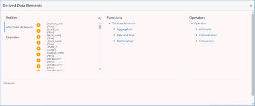
When you select the ‘Add option’, the Specify Expression window is displayed. Here, you can select the required Entities, Functions, and Operators. That is, you can write your expression. Enter the field name and click OK. Now the newly created field name is listed. |
If the Transformation Type is selected as Aggregation: |
|
Derived Data Elements |
|
Name |
Name of the derived field in EDD. Note: Field names must not be more than 30 characters. |
Type |
This shows the Data type of the field. Example: Varchar2, Number, Date, and so on. |
Expression |
When you select the ‘Add option’, the Specify Expression window is displayed. Here, you can select the required Entities, Functions, and Operators. That is, you can write your expression. Enter the field name and click OK. Now the newly created field name is listed. |
Aggregation Properties |
|
Group By |
This is available when Aggregation is selected. |
Having |
This is available when Aggregation is selected. |
To define a new EDD from the DIH Designer window, follow these steps:
1. From the Source or External application,
click Add  .
The External Data Descriptor new window is displayed.
2. In the External Data Store Name section, select Data Source from the drop-down list. The Data Source is the Source you had created. In this example, it is, DRM_SRC_FILES. The values in Defining an External Data Store example are used. The description comes up automatically.
NOTE:
The fields in the External Data Descriptor Specification Details section change as per the Source Code selected.
For HDFS data, the working date format is YYYY-MM-DD.
For the Hive table, the working date format is YYYY-MM-DD.
For the Sybase source database, the date data type is not supported. It must be a timestamp.
Figure 22: External Data Descriptor Data Tab
3. Click Reload/Refresh to
reload/refresh the data elements.
4. Enter the values in the fields as described in the Fields and their Description section.
Figure 23: Read From Template

5. If data needs to be reconciled post-loading, then click the Control tab. In this version, only the Number of Records controls is possible.
Figure 24: External Data Descriptor Controls Tab
6. To transform the EDD, click the Transformation tab.
Figure 25: External Data Descriptor Transformation Tab

7. You can add derivation to data elements of the EDD.
a. Click Add  to
create derived data elements.
b. To edit the
derived data element, click Edit  . The Expression window is
displayed.
c. The expression can be specified using the data elements defined in the Data tab and functions.
Figure 26: Derived Data Elements Window
d. To delete
the derived data element, click Delete  .
.
8. Click the Transformation tab and select the Transformation Type.
a. Select Aggregation and click Edit
 to
view Expression Window.
b. Specify the Group by clause and Having expression, if applicable.
c. Define Derived Data Elements for the field to be aggregated under the previous tab.
NOTE:
It is applicable only in the case of DB2, Oracle, Sybase, My SQL, and Hive.
9. Click Save.
You can edit or view an existing EDD, other than EDDs in Published status.
NOTE:
You cannot edit EDDs in Published status.
To edit or view an EDD, follow these steps:
1. Select the required EDD from the EDD Summary.
2. The details of the selected EDD are displayed. You can modify or view the details.
3. Update the required details.
4. Click Save to save the changes made.
5. Click Save as Draft to save and update later. The status shows as Draft.
This option only checks the higher-order object. That is, if the order has a dependency, you cannot delete it unless the dependency is removed.
For example, assume EDD is used in Connector. Then, unless the Connector is deleted, the used EDD cannot be deleted.
To delete an existing EDD, follow these steps:
1. On the EDD Summary, click Delete . A
confirmation dialog box is displayed.
2. Click Yes. The EDD details are deleted.
NOTE:
Delete is enabled only in the following cases:
If the EDD is not in Published status.
If the EDD is not used by any object.
You can unpublish an EDD only when all the following conditions are met:
· The EDD is in Published status.
· All the connectors using the EDD are unpublished.
To unpublish an EDD, follow these steps:
1. Select the required EDD from the EDD Summary. The details of the selected EDD are displayed.
2. Click Unpublish.
NOTE:
The EDD gets published automatically by the system whenever the higher objects (Connector) using it are published.
Clicking Dependency lists where the entire parent EDD has a dependency.
The Search and Filter option in the UI helps you to find the required information. You can enter the nearest matching keywords to search and filter the results by entering information on the search box. You can search for an EDD using either the name, description, status, or type.
For example, enter the EDD keyword as ‘AATB_ACCT’ in the search box. The entire EDD name with AATB_ACCT is listed.
While defining an EDD, the parameter can be used as a placeholder in a data filename.
For example:
Consider a table with two columns, such as Account number and Balance.
Account Number |
Balance |
|---|---|
A1 |
1000 |
A2 |
1000 |
A3 |
1000 |
A1 |
1000 |
A2 |
1500 |
A3 |
1500 |
In this example, a customer has three accounts (A1, A2, and A3).
The customer has deposited different amounts on January 1st and 2nd 2014. The CSV data files can be created for those two dates as follows:
· The account transaction for January 1st, 2014 is saved as td_contracts_/01012014/.csv
· The account transaction for January 2nd, 2014 is saved as td_contracts_/01022014/.csv
If a parameter, MISDATE, is defined as a runtime, this can be used as a placeholder that substitutes date in mmddyyyy format. That is, the data filename can be mentioned as td_contracts_%#MISDATE%.csv. When this file is called, it substitutes the date in the file name, dynamically, in the runtime.
Parameters Data Types need not always be runtime. They can be Constants or values like Current Date, which can also be used to substitute a value in a data filename.
This tile displays the total number of ADIs that are available in the setup and the number of used ADIs in connectors.
To view the total number of ADIs that are present and used, follow these steps:
1. Click Total or Used on the Application Data Interface.
Figure 27: Application Data Interface Summary Window

The Application Data Interface Summary window is displayed:
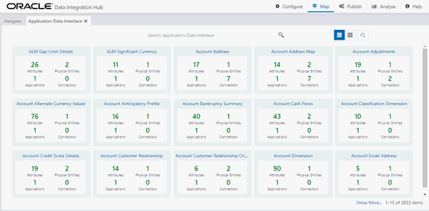
2. Click Analyse to view the Mapping Report for that particular ADI. For more information, see the Error! Reference source not found. section.
3. You can view
the summary details of all the ADIs that are present or used in either
Card view  or
List view
 .
.
4. The search bar helps you to find the required information. You can enter the nearest matching keywords to search and filter the results by entering information on the search box. You can search for an ADI name using either the name or description.
5. Click  to filter
the ADI. The RHS displays the applications you can select to filter. Select
the required application and the feature.
Figure 28: Application Selection Drawer
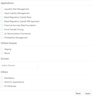
6. Select the required application and then click Apply. The summary window displays the filtered ADIs.
7. Click Reset to deselect the filter options and clear the Subject area.
8. Depending on the ADI selected, there may or may not be additional subtype filters. Such as, for Transactions: Customer Account, there is a Product Class list as subtype filters available. You can choose one or more Product classes to filter the attributes listed below.
9. The selected ADI details are displayed. There are two views for each ADI:
§ Logical View: shows all the attributes and their associated description with additional information. For example, if the attribute is mandatory or not for the selected application, its domain and LOV (List of values) are possible for the particular attribute.
§ Physical View: shows the underlying physical table name of the selected ADI. Selecting the physical table name shows the mapping between the logical attribute name and its corresponding physical column name.
10. At any given time, you can switch between Logical and Physical Views.
11. In Logical View, you can see the attribute details as follows:
§ List with the logical name
§ Description
§ Domain
§ List of values
Figure 29: Logical View Window
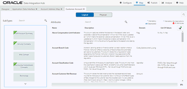
12. Attributes contain:
§ Sensitive
information PII (Personally Identifiable Information)
is displayed with  before
the attribute.
§ Deprecated attributes are shown as strikethrough text.
§ Mandatory attributes have * next to them.
§ Attributes that are mandatory for selected applications have ** next to them.
13. In Logical View, you can search for an attribute name or description.
14. The progress can also be viewed based on the filters applied to this window.
NOTE:
The percentage is calculated based on the number of attributes sourced versus the total number of attributes.
15. In Physical View, click the table name. You can view the attribute name, field name, data type, length, precision, and .format.
16. For example, in the case of ADI with a subtype such as a Customer Account, the physical table name is based on the Subtype. Hence, one or more physical table names are displayed.
17. When you select the table, the respective attribute is displayed.
Figure 30: Physical View Window
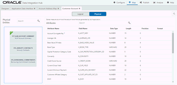
18. In Physical View, you can search with either an attribute name or physical column name.
19. In both Logical and Physical views, you can click the filter.
20. A filter drawer is displayed with options to filter based on applications, OFSAA Module, Logical Domain, and other properties.
21. Select the required application and then click Apply. The Summary window displays the filtered ADIs.
22. Click Reset to deselect all filter options.
23. Click Apply to filter the attribute list.
Connectors allow mapping one or more External Data Descriptors with an Application Data Interface, in the case of “Insert Connectors “or vice versa, in the case of “Extract Connectors”.
Factory-defined and maintained Connectors are available for specific Oracle applications – FLEXCUBE, Oracle Banking Platform, Data Relationship Management, and Accounting Hub Cloud Service. See the User Guides of these applications from the OFSAA Data Integration Application Pack at OHC Documentation Library. You can configure Insert and Extract Connectors for data exchange with other applications.
To create a connector, you must understand each of the icons at the beginning. While creating a Connector, the icons that are displayed are explained as follows:
Icon |
Description |
|---|---|
|
Click this icon to view the list of all External Data Descriptors created in the setup. You can drag the desired EDD on the canvas. |
|
Click this icon to view the list of all ADIs created in the setup. You can drag the desired ADI on the canvas. |
|
Click this icon to open the Mapping window. You can map the source column to the target column in the window. |
|
This component is used for defining a join between two entities. Click this icon to open the window where you can define the join condition between two entities. |
|
This component is used for defining the filter of a given entity. Click this icon to open the window where you can define the filter condition. |
|
This component is used for defining the lookup condition. Click this icon to open the window where you can define the join condition between two entities. |
|
This component is used for defining the Derived column. Click this icon to open the window where you can define an expression, which can be mapped to the target column. |
|
This component is used for transforming flattened hierarchy entities into parent-child hierarchy entities. |
|
This component is used for Transpose (Rows to Columns) for a given entity. Click this icon to open the window where you can define the pivot data element and the new columns, which are transposed from multiple rows of source entity. |
|
This component is used for Transpose (Columns to rows) for a given entity. Click this icon to open the window where you can define the unpivot data element and new rows which are transposed from columns of the source entity. |
|
This component is used for defining a group by and having a clause for Aggregation. Click this icon to open the window where you can define a group by and having a clause for aggregation. |
|
Click this button to remove all the nodes added to the canvas. |
|
This is displayed on the connector window when the connector is published and is opened in view mode. The connector is not editable. |
|
This is displayed on the connector window when the connector is not published. The connector is editable. |
The connector allows mapping one or more External Data Descriptor with Application Data Interface. It allows mapping of one or more ADI with EDD as well, in the case of extract type connector.
There are pre-built Connectors for Oracle applications such as FLEXCUBE, Oracle Banking Platform, and so on. For other applications, you need to define Connectors for your EDDs.
To create a Connector for loading data into OFSAA, follow these steps:
1. On the Connector Summary window, click .
.
Or:
2. From the Data Integration Hub Designer window, click  in Insert
Connectors, to move the data from an EDD to an ADI.
3. The New Connectors Definition window is displayed.
4. To define a connector, you must have a source with EDD and a target, which is ADI.
5. Click Source to select the required EDDs. Here, you can filter your selection based on the EDS selected. The EDD node’s color depends on the source system type.
Figure 31: Connectors - Source

For example:
§ File types are in blue.
§ Oracle types are in red.
§ HDFS types are in orange.
6. If you select ‘OBP_STAGE_SRC’ as the EDS, it displays the EDDs for that particular EDS selected.
7. Click Search  to
search for a particular EDD. You can select multiple EDS.
8. Select the required EDD and drag it to the canvas.
9. Click Target. Here you can filter ADIs based on the application selected.
Figure 32: Connectors - Target

10. Click Search to search for a particular ADI.
11. Select the required ADI. Drag it to the canvas and then link the input and output nodes.
12. Click the input white circle. The anchor symbol is displayed. Drag and drop the line to link it to the required component.
Figure 33: New Connector Window

13. At any given time, you can right-click the node to either delink or remove links/outline or delete a node.
14. To edit or
view the properties, on the Connector window,
click .
.
15. In Connector Details, enter the name and description for the connector.
Figure 34: Connector Details Window
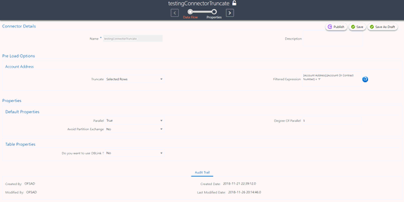
16. In Pre Load Options, select the truncate option to be defined in the target. To remove data from the table as per the truncate option specified, select Truncate.
§ Select No, if you do not wish to truncate the table before loading.
§ If you select Partial Truncate, provide the Partition Name. The parameter name can be provided here. If you want to truncate a partition, the Partial Truncate option must be selected. Specify the partition to be truncated before load.
NOTE:
For multi-target loads, the truncate type must be the same for all targets. However, truncate expression may vary.
§ Select Full Truncate to fully truncate. Here no expression is required. If you want to truncate the entire table, the Full Truncate option must be selected.
§ Select Selected Rows to truncate on the selected expressions. If you remove specific rows, the selected rows option must be selected. Specify the filter condition for the rows to be deleted. Specific rows are removed from the table before load.
NOTE:
If OFSAA is hosted on a Big Data environment, then the Truncate with Selected Rows option is not supported.
— Click Edit  to
filter the selected rows.
— Select the required entity and click Validate. This validates the expression.
— Click Ok once the expressions are selected.
In the image, truncate details are selected for Account Address.
17. In Properties, select the Default Properties, File Properties, and Table Properties if you have selected a default type or file type or a table type respectively.
NOTE:
See the Connector Properties section for more information on the properties.
To create a Connector for processing data within OFSAA, follow these steps:
1. To create
a new connector, on the Connector Summary window,
click .
.
Or:
2. From the Data Integration Hub Designer window, click  from Process Connectors
to move the data within an ADI.
3. The New Connectors Definition window is displayed.
4. To define a connector, you must have an ADI for source and another for Target.
5. Click Source to select the required ADIs.
6. Click Search
 to
search for a particular ADI. You can select multiple ADIs.
7. Select the required ADI and drag it to the canvas.
8. Click Target. Here you can filter ADIs based on the application selected.
Figure 35: Connectors - Target

9. Click Search
 to
search for a particular ADI.
10. Select the required ADI. Drag it to the canvas and then link the input and output nodes.
11. Click the input white circle. The anchor symbol is displayed. Drag and drop the line to link it to the required component.
Figure 36: New Connector Window

12. At any given time, you can right-click the node to either delink or remove inlinks / outlink or delete a node.
13. To edit or
view the properties, on the Connector window,
click .
.
14. In Connector Details, enter the name and description for the connector.
Figure 37: Connector Details Window
15. In Pre Load Options, select the truncate option to be defined in the target. When you select Truncate, it removes data from the table as per the truncate option specified.
§ Select No, if you do not wish to truncate the table before loading.
§ If you select Partial Truncate, provide the Partition Name. The parameter name can be provided here.
§ If you want to truncate a partition, the Partial Truncate option must be selected. Specify the partition to be truncated before the load.
NOTE:
For multi-target loads, the Truncate type must be the same for all targets. However, truncate expression may vary.
§ Select Full Truncate to fully truncate. Here no expression is required. If you want to truncate the entire table, the Full Truncate option must be selected.
§ Select Selected Rows to truncate on the selected expressions. If you want to remove specific rows, the selected rows option must be selected. Specify the filter condition for the rows to be deleted. Specific rows are removed from the table before load.
NOTE:
If OFSAA is hosted on a Big Data environment, then the Truncate with Selected Rows option is not supported.
— Click Edit  to
filter the selected rows.
— Select the required entity and click Validate. This validates the expression.
— Click Ok once the expressions are selected.
In the image, truncate details are selected for Account Address.
16. In Properties, select the Default Properties, File Properties, and Table Properties if you have selected a default type or file type, or a table type respectively.
NOTE:
See the Connector Properties section for more information on the properties.
To create a Connector for extracting data from OFSAA, follow these steps:
1. On the Connector Summary window, click .
.
Or:
2. From the Data Integration Hub Designer window, click  from Extract
Connectors to move the data from an ADI to an EDD. The New
Connectors Definition window is displayed.
3. To define a connector, you must have a source with EDD and a target, which is ADI.
4. Click Source to select the required ADIs.
5. Here, you can filter your selection based on the ADI selected. The ADI node’s color depends on the source system type.
6. Click Search
 to
search for a particular ADI.
7. Select the required ADI. Drag it to the canvas and then link the input and output nodes.
Figure 38: Connectors - Source
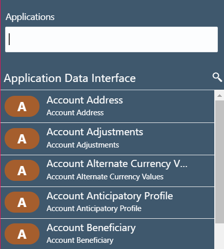
For example:
§ The file types are in blue.
§ Oracle types are in red.
§ HIVE types are in brown.
8. Click Target. Here you can filter EDS based on the application selected.
Figure 39: Connectors - Target

9. If you select ‘OBP_STAGE_SRC’ as the EDS, it displays the EDDs for that particular EDS selected.
10. Click Search
 to
search for a particular EDD. You can select multiple EDS.
11. Select the required EDD and drag it to the canvas.
12. Click the input white circle. The anchor symbol is displayed. Drag and drop the line to link it to the required component.
Figure 40: New Connector Window

13. At any given time, you can right-click the node to either delink or remove inlinks / outlink or delete a node.
14. To edit or
view the properties, on the Connector window, click .
.
15. In Connector Details, enter the name and description for the connector.
Figure 41: Connector Details Window
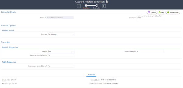
16. In Pre Load Options, select the truncate option to be defined in the target. When you select Truncate it removes data from the table as per the truncate option specified.
§ Select No, if you do not wish to truncate the table before loading.
§ If you select Partial Truncate, provide the Partition Name. The parameter name can be provided here. If you want to truncate a partition, the Partial Truncate option must be selected. Specify the partition to be truncated before load.
§ Select Full Truncate to fully truncate. Here no expression is required. If you want to truncate the entire table, the Full Truncate option must be selected.
§ Select Selected Rows to truncate on the selected expressions. If you remove specific rows, the Selected Rows option must be selected. Specify the filter condition for the rows to be deleted. Specific rows are removed from the table before load.
NOTE:
If data is extracted into a Big Data environment, then the Truncate with Selected Rows option is not supported.
— Click Edit  to
filter the selected rows.
— Select the required entity and click Validate. This validates the expression.
— Click Ok once the expressions are selected.
In this image, truncate details are selected for the Account Address.
17. In Properties, select the Default Properties, File Properties, and Table Properties in case you have selected a default type or file type or a table type respectively.
NOTE:
See the Connector Properties section for more information on the properties.
To manage existing connectors, follow these steps:
1. From the Data Integration Hub Designer window, to manage Connector, click links in each group to access details.
Figure 42: Connector Designer Window
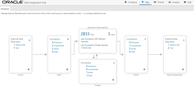
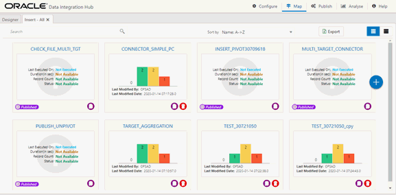
2. To manage Insert Connectors, click the links under Insert.
Figure 43: Insert Connectors

The Insert - Connectors window is displayed.
Figure 44: Insert Connectors Window
3. To manage Process Connectors, click the links under Process.
Figure 45: Process Connectors

4. The Process - Connectors window is displayed.
Figure 46: Process Connectors Window

5. To manage Extract Connectors, click the links under Extract.
Figure 47: Extract Connectors

The Extract - Connectors window is displayed.
Figure 48: Extract Connectors Window

6. The Connectors window lists all connectors that are defined in the setup. It displays the entire insert, process, and extract type connector details. It gives information about the number of parameters, EDS, EDDs, and ADI used in a specific connector.
7. Click Export. The Select Export Columns window is displayed.
Figure 49: Select Export Columns
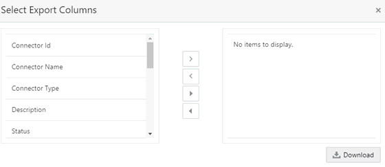
8. Select the required ID and click Download. The list of connectors is exported to an Excel sheet with Connector IDs and Connector Name. This lists both insert and extract type connector details.
9. Click  to view
the connectors in the card view. It gives information about the number
of parameters, EDS, EDDs, and ADI used in a specific connector.
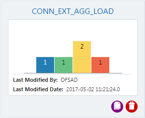
In case, the connector is published:
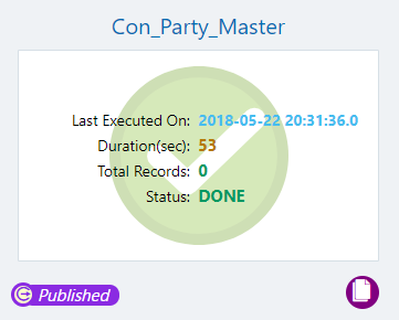
10. Click the
Navigation icon  . The Connectors
are displayed in the list view.

In case, the connector is published:

To use the filter component, follow these steps:
1. Drag and drop
the Filter  component on
the canvas to define a filter on an entity. For example, EDD (insert
connector) / ADI (Process and Extract Connector).
2. Alternatively, you can navigate to the component using the Tab key and use key board shortcut Ctrl C (Copy) and Ctrl V (Paste) to copy and paste the component on the canvas. To position the component, select the component and use arrow keys on the keyboard to reorder.
3. It accepts input only from an entity and it can have only one output.
4. If you have multiple entities selected, and you want to have a filter for more than one entity, then you must select as many numbers of filters, connect to the respective entity, and then define their expressions.
5. For example, to add a filter to three entities, drag three filters.
Figure 50: Filter New Connector Window
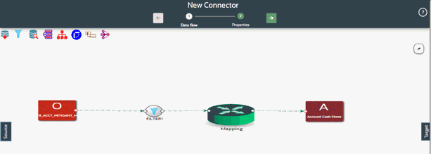
6. At any given time, right-click the filter component to either delink or remove inlinks / outlinks or delete the filter component.
7. Double-click filter component. The Filter Expression window is displayed.
8. The selected entities and parameters are displayed in the Filter Expression window.
9. Specify the required filter expression using columns and parameters.
10. Click Validate to verify the correctness of the SQL expression.
11. Click OK.
NOTE:
You do not need to add the ‘WHERE’ clause for the filter.
1. For File data loading, use the filter expression of the Number type along with single quotes. For example: N_DRAWN_AMOUNT ='40000'.
2. For the Date field, see To_CHAR function for comparison.
3. Parameters can also be used in the filter expression. The date format must be a valid SQL date format.
For Example:
[EDD_GL_DATA].[EXTRACTION_DATE] = TO_DATE(#DIHDEV.MIS_DATE,’dd-MM-yyyy’)
12. If the Source type is Hive, the filter expressions must conform to the following restrictions:
— Must be valid HiveQL
— Does not include Oracle built-in or user-defined functions
— Does not include Subqueries
— Includes Hive built-in functions only
— Parameters can also be used in the filter expression. MISDATE can also be passed dynamically so that it is loaded from the Batch Execution window. The date format specified must be valid Hive Date format i.e. yyyy-MM-DD
— For Example:
— Filter Expression in Connector:-[EDD_GL_DATA].[EXTRACTION_DATE] = #DIHDEV.MIS_DATE
— MISDATE Parameter in Batch:
— MISDATE=$MISDATE:yyyy-MM-dd
To use the join component, follow these steps:
1. Drag and drop
the Join  component
on the connector window to link multiple entities. For example, EDDs
(insert connector) / ADIs (Process and Extract Connector).
2. Alternatively, you can navigate to the component using the Tab key and use key board shortcut Ctrl C (Copy) and Ctrl V (Paste) to copy and paste the component on the canvas. To position the component, select the component and use arrow keys on the keyboard to reorder.
3. The Join component accepts input from two entities.
Figure 51: Join New Connector Window
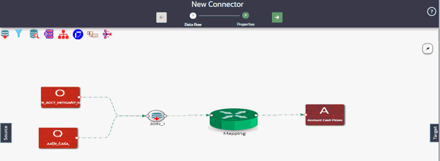
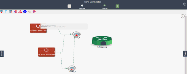
4. To join more than two entities, drag another join component. Link the output of the first join to the input of the second join and then connect the other entities. You can repeat this for multiple entities. Select the Source Entity and click Ok.
Figure 52: Multiple Join Entities
5. At any given time, right-click the join component to either delink or remove inlinks / outlinks or delete a join component.
6. Double-click the join component to define a join condition. The Join window is displayed:
7. Here you see the selected entities in the left and right tab.
Figure 53: Join Window
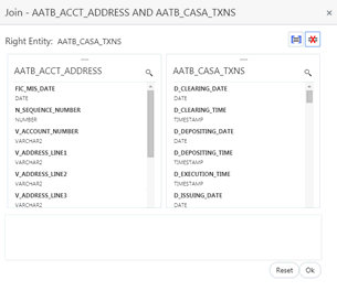
8. You can drag and reorder the left and right tab to choose the right/left entity in a join condition.
9. To join entities,
the select column from the left and right tab and click Add
Join .
This displays the joined entities. You can join multiple entities.

10. To remove
two joined conditions, select two columns from the left and right tab,
and click Remove Join .
The joined condition is removed from the list.
11. Click Reset to reset all the joined conditions.
12. Click Ok.
NOTE:
This creates an inner join between the connected EDDs.
To use the lookup component, follow these steps:
1. Drag and drop
the Lookup  component on
the canvas to define a filter on an entity. For example, EDD (insert
connector) / ADI (Process and Extract Connector).
2. Alternatively, you can navigate to the component using the Tab key and use key board shortcut Ctrl C (Copy) and Ctrl V (Paste) to copy and paste the component on the canvas. To position the component, select the component and use arrow keys on the keyboard to reorder.
3. You can lookup values from an entity using this component.
NOTE:
The lookup component accepts input from two entities. One from Value Entity and the other one from the Lookup Entity.
Figure 54: Lookup New Connector Window
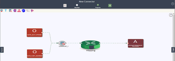
4. At any given time, right-click the lookup component to either delink or remove inlinks / outlinks or delete a lookup component.
5. Double-click the lookup component to define a lookup condition. The Lookup window is displayed:
6. Here you see the connected entities in the left and right tab.
Figure 55: Lookup Window
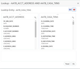
7. The entity that is on the right side of the window is the lookup entity. You can change the lookup entity by moving it to the right side. The “LookUp Entity” field displays the entity specified for lookup.
8. To specify
lookup condition, select data elements from left and right entities and
click Add Join  .
Lookup condition is displayed as follows:

9. To remove
a lookup condition, select data elements from left and right entities
and click Remove Join . The lookup condition is removed
from the list.
10. Click Reset to reset the lookup condition.
11. Click Ok.
NOTE:
This creates a left outer join between the connected entities.
To use the aggregation component, follow these steps:
1. Drag and drop
the Aggregation  component
on the canvas to define an aggregation on an EDD.
2. Alternatively, you can navigate to the component using the Tab key and use key board shortcut Ctrl C (Copy) and Ctrl V (Paste) to copy and paste the component on the canvas. To position the component, select the component and use arrow keys on the keyboard to reorder.
3. It accepts input only from an EDD and it can have only one output.
4. If you have multiple EDDs to be aggregated then you must select as many numbers of aggregation components, connect to the respective EDD, and then define their group by and having clauses.
5. For example, to add aggregation to three EDDs, drag three aggregation components.
Figure 56: Aggregation for an EDD New Connector Window
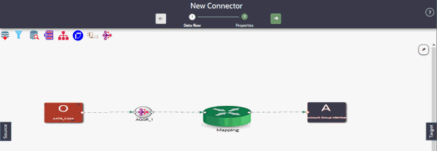
6. At any given time, right-click the aggregation component to either delink or remove inlinks / outlinks or delete the aggregation component.
7. Double-click the aggregation component to define an aggregation condition. The Aggregation window is displayed:
8. Here you see the selected EDD under the entity tab.
Figure 57: Aggregation Window
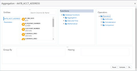
9. Select the group by columns and specify an expression for the having clause.
10. Click Reset to reset all the aggregation conditions.
11. Click Validate to verify the correctness of the SQL expression.
12. Click Ok.
To use the aggregation component, follow these steps:
1. Drag and drop
the Aggregation  component
on the canvas to define an aggregation on the entire dataset.
2. Alternatively, you can navigate to the component using the Tab key and use key board shortcut Ctrl C (Copy) and Ctrl V (Paste) to copy and paste the component on the canvas. To position the component, select the component and use arrow keys on the keyboard to reorder.
3. It accepts input only from the mapping component or filter that is connected to the mapping component.
Figure 58: Aggregation for Entire Dataset New Connector Window
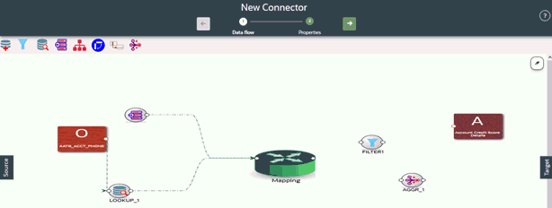
4. At any given time, right-click the aggregation component to either delink or remove inlinks / outlinks or delete the aggregation component.
5. Double-click the aggregation component to define an aggregation condition. The Aggregation window is displayed:
6. Here you see the selected EDD under the entity tab.
Figure 59: Aggregation Window
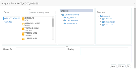
7. Select the group by columns and specify an expression for the having clause.
8. Click Reset to reset all the aggregation conditions.
9. Click Validate to verify the correctness of the SQL expression.
10. Click Ok.
To use the Transpose (Rows to Columns) component, follow these steps:
1. Drag and drop
the Transpose (Rows to Columns)  component
on the canvas to define a Transpose (Rows to Columns) component on an
EDD.
2. Alternatively, you can navigate to the component using the Tab key and use key board shortcut Ctrl C (Copy) and Ctrl V (Paste) to copy and paste the component on the canvas. To position the component, select the component and use arrow keys on the keyboard to reorder.
3. It accepts input only from an EDD and it can have only one output.
4. If you have multiple EDDs selected, and you want to have a Transpose (Rows to Columns) component for more than one EDD, then you must select as many numbers of Transpose (Rows to Columns) components, connect to the respective EDD, and then define their expressions.
NOTE:
The output can be connected to Join, Lookup, and Mapping.
For example, to add the Transpose (Rows to Columns) component to three EDDs, drag three Transpose (Rows to Columns) components.
Figure 60: Transpose (Rows to Columns) for an EDD New Connector Window
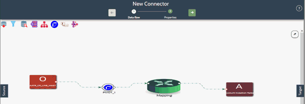
5. At any given time, right-click the Transpose (Rows to Columns) component to either delink or remove inlinks / outlinks or delete a Transpose (Rows to Columns) component.
6. Double-click the component to transpose the entity rows into columns. The Transpose Row to Column window is displayed.
7. Here you see the selected EDD and parameters.
Figure 61: Transpose (Rows to Columns) Window
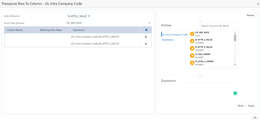
8. Specify the pivot data element to transpose rows into columns.
9. Specify the Row Value – Transposed Column – Expression combination. You must have a minimum of two combinations.
10. Click Review to review the transformation. The Review Transformation window displays the sample of the transformation data.
Figure 62: Review Transformation Window

11. Click Ok.
To use the Transpose (Columns to Rows) component, follow these steps:
1. Drag and drop
the Transpose (Columns to Rows)  component
on the connector window to define a Transpose (Columns to Rows) component
on an EDD.
2. Alternatively, you can navigate to the component using the Tab key and use key board shortcut Ctrl C (Copy) and Ctrl V (Paste) to copy and paste the component on the canvas. To position the component, select the component and use arrow keys on the keyboard to reorder.
3. It accepts input only from an EDD and it can have only one output.
4. If you have multiple EDDs selected, and you want to have Transpose (Columns to Rows) component for more than one EDD, then you must select as many numbers of Transpose (Columns to Rows) components, connect to the respective EDD, and then define their expressions.
NOTE:
The output can be connected to Join, Lookup, and Mapping.
5. For example, to add the Transpose (Columns to Rows) component to three EDDs, drag three Transpose (Columns to Rows) components.
Figure 63: Transpose (Columns to Rows) for an EDD New Connector Window
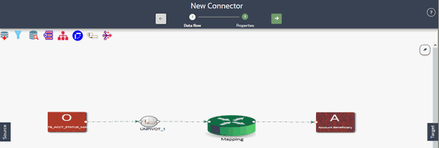
6. At any given time, right-click the Transpose (Columns to Rows) component to either delink or remove inlinks / outlinks or delete a Transpose (Columns to Rows) component.
7. Double-click the component to transpose the entity columns into rows. The Transpose Column to Row window is displayed.
8. Here you see the selected EDD and its parameters.
Figure 64: Transpose (Columns to Rows) Window
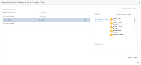
9. Specify the Unpivot Data Element to transpose columns into rows.
10. Specify the Header Column Name and Value Column Name.
11. Specify the Column Value (Header column) and Expression Pair (Value column) for each transposed row. You must have a minimum of two pairs.
12. After specifying the Unpivot Data Elements, click Auto Transpose. This will transpose columns into rows based on the unpivot data elements selected.
Figure 65: Transpose (Columns to Rows) Window
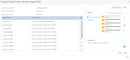
13. You can also
click  drag
and drop the columns.
14. Click Review to review the transformation. The Review Transformation window displays the sample of the transformation data.
Figure 66: Review Transformation Window
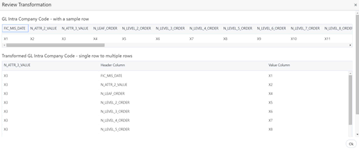
15. Click Ok.
To use the Derived Column component, follow these steps:
1. Drag and drop
Derived Column  component
on the canvas.
2. Alternatively, you can navigate to the component using the Tab key and use key board shortcut Ctrl C (Copy) and Ctrl V (Paste) to copy and paste the component on the canvas. To position the component, select the component and use arrow keys on the keyboard to reorder.
3. Connect the Derived Column to the mapping.
NOTE:
The output must be connected to the mapping.
Figure 67: Derived New Connector Window
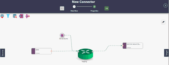
4. At any given time, right-click the expression component to either delink or remove outlinks or delete an expression component.
5. Double-click the Derived Column component.
6. The Derived Expression window for Derived Column is displayed.
Figure 68: Derived Column Window
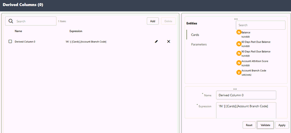
7. Click Add to define a new Derived Column.
8. Click Edit to specify the name and expression of the Derived Column. You see the selected EDDs in the right tab.
9. Click Validate in case you wish to verify the correctness of the SQL expression.
10. Click Apply.
11. Repeat the steps for as many Derived Columns.
12. Click Ok.
1. Double-click Mapping. The Mapping window is displayed.
2. Alternatively, you can navigate to the component using the Tab key and use key board shortcut Ctrl C (Copy) and Ctrl V (Paste) to copy and paste the component on the canvas. To position the component, select the component and use arrow keys on the keyboard to reorder.
NOTE:
The input and output for the Mapping component must be connected before specifying the mappings.
3. The mapping window displays the EDDs and ADIs and their respective data / derived data elements.
Figure 69: Mapping Window
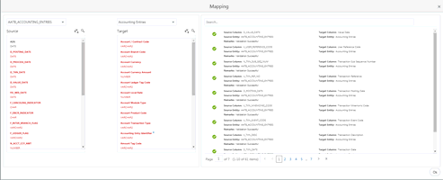
4. Click a Data
Element under Source, Attribute under Target, and then click Map
 . On the RHS, the column mapping
is displayed.
5. The following validations are done for the mapping:
a. Data Type Validation
b. Data Length Validation
c. Data Precision Validation
6. If validation
is successful, it displays Successful  next
to the mapping.
7. If any of
the validations fail, it displays Warning next to the mapping.
8. At any given time, you can select Unmap to unmap the source and target.
9. Click Auto-Map  to
auto map a source and target.
NOTE:
Auto-mapping is done by matching the logical/physical column name of both the source or target.
10. In the Source
column, click Filter  . Enable it to view the unmapped
items.
NOTE:
The mapped columns are displayed in red.
11. In the Target
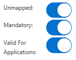
column, click Filter . Enable it to view the unmapped,
mandatory, and valid for applications.
12. Under the Target column, you can hover over each item to see the details. It provides the description, length, and scale information.
13. Click Search  to
search for a column name under the Source or Target column list.
14. Click Delete  to
delete all the mappings. You can also delete individual mappings by selecting
the cross symbol next to the column mapping.
15. Click Import Mapping  to
import a mapping Excel. Choose mapping Excel from the file browser.
16. Click Export Mapping  to
export the mapping information. This downloads an Excel file.
17. Click Search to search for a column
mapping. You can search for an item based on the source column name, target
column name, source or target entity, or a remark.
To use the Flatten table to PC Hierarchy Transformation, follow these steps:
1. Drag and drop
the PC Hierarchy  component
on the canvas.
2. Alternatively, you can navigate to the component using the Tab key and use key board shortcut Ctrl C (Copy) and Ctrl V (Paste) to copy and paste the component on the canvas. To position the component, select the component and use arrow keys on the keyboard to reorder.
3. Connect the Derived Column to the mapping.
NOTE:
The output must be connected to the mapping.
Figure 70: PC Hierarchy New Connector Window
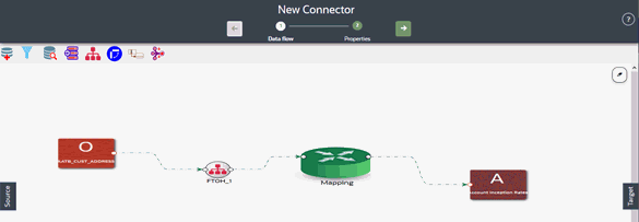
4. At any given time, right-click the expression component to either delink or remove outlinks or delete an expression component.
5. To define the expression, double-click the Flatten table to the PC hierarchy. The Flattened Table to Hierarchy window is displayed.
Figure 71: Flattened Table to Hierarchy Window
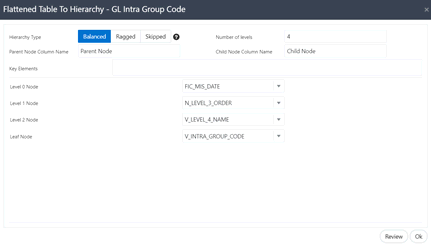
6. Choose the
Hierarchy Type. The types of hierarchy supported are Balanced, Ragged,
and Skipped. Click  to view the details
and understand how the hierarchies are defined.
Figure 72: Flattened Table to Hierarchy Window
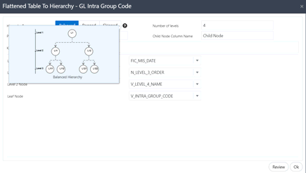
7. Specify the Number of levels in the hierarchy. This field accepts only numbers.
8. Specify the Parent Node Column name and Child Node Column name which are used in the mapping.
9. Select the Key Elements from the drop-down list.
10. Select all nodes. You can change the date and or other details from the drop-down list.
11. Click Review to view the transformation changes.
12. Click Ok.
Alias refers to an assumed name or pseudonym assigned to an EDD or an ADI as you define Connectors, much like table aliases used in SQL statements. Aliases allow an EDD or an ADI to be referred in multiple joins, lookups, or both, within the same Connector definition, each in a distinct context.
Aliases are automatically initiated by DIH as and when required while defining Connectors. The following scenario explains the mechanism:
1. Drag and drop an ADI or EDD more than once, for use in separate joins or looks-up, on the New Connector canvas. DIH initiates the specification of an alias by displaying the Specify Alias dialog box.
Figure 73: Specify Alias
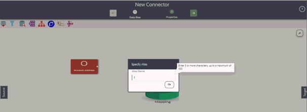
2. Enter a name of your choice under Alias Name and click Ok. Note that the Alias Names must be unique within a Connector.
Figure 74: New Connector Window
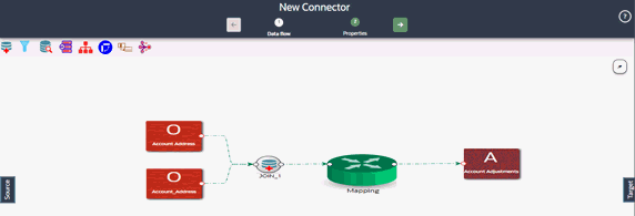
The properties by default have some values. For every connector, it needs to be reviewed. Generally, no change is required.
The following table describes the fields in the connector properties.
Fields
|
Applicable Values |
Description
|
Default Value |
|---|---|---|---|
Loading mechanism |
· External Table · SQLLDR |
There are two options External Table and SQLLDR. · External Table - If the loading mechanism is selected as an External table, then the file-landing zone must be located/mounted on the database server. · SQLLDR - This option is only applicable when OFSAA is hosted in Oracle Database. The file-landing zone must be located or mounted on the server where the ODI agent is running. Oracle Database Client must be installed in the server where the ODI agent is running. NOTE: If the loading mechanism is selected as External Table, the file must be located in the same place as the database server. If the target database type is HDFS, only the External Table option is enabled. If the target database type is Oracle, provide CREATE DIRECTORY role to the Atomic schema. Also, the path/folder used in the directory must have read and write permissions. |
SQLLDR |
DIRECT |
· True · False |
Direct path load of SQLLDR. Values can be True and False. |
TRUE |
Parallel |
· True · False |
Parallel option. True means the loading happens with parallel option and False means it happens sequentially. |
TRUE |
Degree of Parallel |
Integer |
Decides the degree of parallelism. The values specified here must be a number. |
0 |
No: of Errors |
Integer |
Shows the number of errors allowed for the SQLLDR and External Table to proceed. That means a single record fails the job fails. The values specified here must be a number. |
0 |
Maximum Discard |
Integer |
Discarded records allowed for SQLLDR. This must be set to a very high number when using multiple subtypes under an ADI. That means it is multiple targets. |
1 |
XML date Format |
Valid XML Date format |
In this field, you can define the format of the XML Date. Example: MMDDYYYY. |
MMDDYYYY |
Avoid Partition Exchange |
· Yes · No |
The property option decides whether the Partition Exchange method is used during the data load. NOTE: If the connector execution fails during partition exchange for some reason, then it can be avoided by choosing the option "Yes". |
No |
Do you want to use Data Pump?
|
· Yes · No |
There are two values ‘Yes’ and ‘No’. If the value is ‘Yes’, it indicates that the Oracle Database source is loaded into OFSAA using the Data Pump method. Alternatively, the standard way of using the DBLink method is followed. NOTE: The following access is required for the data pump option. Grant create any directory to Source schema Grant create any directory to the target schema Grant execute on DBMS_FILE_TRANSFER to the target schema Grant execute on utl_file to the source schema |
No |
Source and Target in the Same Environment?
|
· Yes · No |
This parameter is used only if the Data Pump is used. If the value is, ‘Yes’ then the file transfer step is not performed during loading. Alternatively, it will transfer files from source to target folder using DBLink. |
Yes |
Source Dump Location
|
/src/tmp |
Specify a folder/path that is accessible by the Source Oracle Database to create the dump file. |
/src/tmp |
Target Dump Location
|
/target/tmp |
Specify a folder/path that is accessible by Target Oracle Database to read the dump file. |
/target/tmp |
Number of Splits for Dump File |
Integer |
Specify a number to transfer the files in parallel chunks. For example, 3 indicates that the dump file is split into three and transferred separately. This is to improve the performance of file transfer. The values specified here must be a number. |
0 |
Effective Dated Key for Result Area? |
· Yes · No |
This parameter is used for loading data into the result area. It decides whether it will perform a lookup into a dimension for the latest record, or an effective dated record. To get the latest record, it appends f_latest_record_indicator =’Y’ and for effective dated it appends mis_date between d_record_start_date and d_record_end_date. NOTE: For extraction data or any date attribute, effective dating does not work. If this parameter is selected as “Yes” and any date field needs to be loaded into an Extraction date or any other date field, then do not rely on surrogate key generation. Use the derived column and enter the value in the format “YYYYMMDD” as a number. |
No |
Do you want to use DBLink? |
· Yes · No |
This parameter is used to specify the source database connection method. There are two values ‘Yes’ and ‘No’. If the value is ‘Yes’, it indicates a connection source database is created using the DBLink method. If the value is ‘No’, it indicates a connection to the source database is created using the JDBC URL. |
No |
Hive Date Format |
yyyy-MM-dd |
This parameter is used to specify the date format for date columns in Hive source. |
yyyy-MM-dd |
Do you want to use Big Data SQL? |
· Yes · No |
This parameter is used to specify the loading mechanism from the HIVE source. If you have selected Yes, Oracle Big Data SQL is used. NOTE: The following are the pre-requisites for this method: · The Oracle Big Data SQL is installed and configured on Oracle Big Data Appliance and Database (OFSAA) machines. · In the OFSAA database, a directory named DEFAULT_DIR is created. · The folder/system path specified for the above directory must be accessible to the database (OFSAA). For more information see: https://docs.oracle.com/bigdata/bda45/BDSUG/installing.htm#BDSUG-GUID-5CDA332E-8CB8-42CC-8922-09295E22B0E5 If you have selected No, Oracle Loader for Hadoop is used. NOTE: The following are the pre-requisites for this method: § Oracle Loader of Hadoop connectors is installed and configured in the source system. § The ODI agent is also configured for OLH. For more information see: https://docs.oracle.com/cd/E72987_01/odi/odi-big-data/setup.htm#ODIBD117 |
No |
To edit or view a connector, follow these steps:
1. To edit or view a connector, you can select the required connector from the connector summary.
NOTE:
You can edit an existing connector, other than connectors in Published status. To edit a connector in Published status, you must first un-publish it and then open it.
2. The connectors are created open in their respective view mode.
3. The details of the selected connector are displayed. You can modify or view the details.
4. The Connector Name cannot be edited. Update the other required details.
5. Click Save to save the changes made.
6. To make changes to a published connector, click ‘Unpublish’. The ‘Unpublish’ option clears the ODI metadata that has been created during publishing. Update the required changes and then click Publish. The updated changes are synced in ODI.
To copy an existing Connector, follow these steps:
1. Click Copy  for
the required connector. A Save As dialog box
is displayed.
Figure 75: Save Connector As
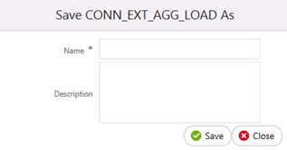
Depending on the view in which the original connector is created, the copied connector will have the same view.
2. Enter the name and description.
3. Click Save. The Connector details are saved with a new specified connector name. The existing connector remains unmodified.
To delete an existing Connector, perform the following steps:
1. Click Delete  for
the required connector. A confirmation dialog box is displayed.
2. Click Yes to delete a connector. The Connector is deleted. If you do not wish to delete, click No.
The Search and Filter option in the UI helps you to find the required information. You can enter the nearest matching keyword to search, and filter the results by entering information on the search box. You can search for a connector with either the name, description, or status of the connector.
For example, enter the keyword as ‘CON_DRM_GL’ in the search box. All the connector names with 'CON_DRM_GL’ are listed.
You can sort the list by connector name or modified date (ascending or descending order).
Parameters are used while defining the mapping, between EDD to ADI. While mapping the ADI to EDD, the fields or columns within the ADI needs to be mapped to the fields in EDD. If there are no corresponding extracts in EDD, parameters can be used to identify the default values for certain ADI elements. Also, parameters can be used while defining derived columns during mapping.
For example, if you want to use the Runtime MIS date as the parameter, then it must be converted to date first. The following is the expression:
To_char(to_date(#DIHDEV.MIS_DATE,’dd-MON-YYYY’),’MM’)
NOTE:
Runtime batch MIS date is in string format. It must be converted to DATE. The date format used here must be a valid SQL date format.