Setting Up Single Signon
This section provides an overview of single signon and participating nodes, and discusses how to:
Define all participating nodes.
Identify trusted nodes.
Adding remote nodes to the integration network.
Testing single signon.
In a PeopleSoft environment, single signon is deployed for a number of reasons. For users, single signon provides the ability for them to navigate freely within a environment of multiple applications after being authenticated only once. For integration of PeopleSoft applications and systems, single signon identifies those systems that are trusted participants in the integration. With unified navigation, single signon is deployed for both purposes: to identify those trusted systems and to allow users to navigate freely to resources on those trusted systems.
The first step to configuring single signon is to define the participating nodes from each content provider system in the designated portal system, and conversely, to define the default local node of the portal system in each content provider system. Then, in each content provider system, define the participating nodes from the portal system and from all other content provider systems in the cluster.
Image: Remote nodes in a unified navigation configuration
The following diagram illustrates three systems participating in unified navigation: HCM (the designated portal system), FSCM, and CRM.
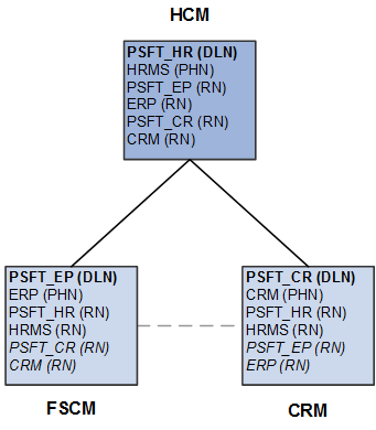
Under each system, the default local node is highlighted in bold and identified with the notation (DLN). For example, on the HCM system, the default local node is PSFT_HR. On the FSCM system, the default local node is named PSFT_EP. The portal host nodes are identified with the notation (PHN). On the FSCM system, the portal host node is named ERP. On the CRM system, the portal host node is named CRM.
Important! Unified navigation supports same portal integration only—for example, EMPLOYEE portal to EMPLOYEE portal, CUSTOMER portal to CUSTOMER portal, or PARTNER portal to PARTNER portal, and so on. Moreover, you should always use the content provider system's portal host node to create remote folders or import pagelets.
Finally, under each system, the remote nodes that need to be defined are identified with the notation (RN). For example, on the HCM system, four remote nodes would need to be defined: PSFT_EP, ERP, PSFT_CR, and CRM. On each of the content provider systems, the two remote nodes representing the portal system would need to be defined at a minimum: PSFT_HR and HRMS. Then, on each content provider system, configure each participating node from each of the other content provider systems. These additional remote nodes are also designated with (RN) and are highlighted in italics.
Note the following when creating node definitions:
Using delivered (standard) node names simplifies the number of steps to complete the integration.
Each node name must be unique across all of the participating systems.
For example, multiple copies of a PeopleSoft application can be federated as content provider systems in a cluster—for example, two copies of PeopleSoft FSCM. You must rename both the default local node and portal host node on one of the copies—for example, PSFT_EP2 and ERP2.
When using non-standard (non-delivered) node names, you must create node definitions for these nodes in each participating system.
This section discusses how to:
Define default local nodes.
Define portal host nodes.
Defining Default Local Nodes
To define default local nodes on all systems:
-
Access the Configure Unified Navigation navigation collection. (See Configure Unified Navigation Fluid Navigation Collection.)
In the Configure Unified Navigation navigation collection, expand the Single Signon Setup section and select the Configure Node for SSO link to open the Nodes page in the target area.
If the node name already exists in the system, then select that node definition. Otherwise, add a new value for the non-standard node name.
Select the Node Definitions page:
Enter a description for the node.
Verify that the node type is PIA.
For default local nodes, the Default Local Node, Local Node, and Active Node check boxes must be selected.
Note: When configuring a remote node definition for this node, only the Active Node check box must be selected.
For default local nodes only, set the authentication option to Password or Certificate. If the authentication type is password, enter a node password.
Note: When configuring a remote node definition for this node, you must enter the same node password.
Enter the default user ID for the node.
Note: When configuring a remote node definition for this node, you must enter the same default user ID. If necessary, create a user profile for this ID.
Create a check token ID for the node, which is required for single signon configurations.
Note: When configuring a remote node definition for this node, you must enter the same check token ID.
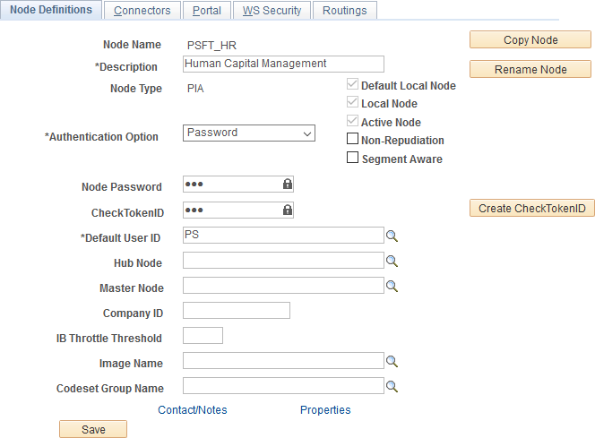
Image: Node Definitions page showing a default local node
This example illustrates the fields and controls on the Node Definitions page showing the default local node for the portal system (HCM).
Select the Connectors page:
Enter the ID for the shared integration gateway in the Gateway ID field.
Note: When configuring a remote node definition for this node, use the same ID.
Enter PSFTTARGET as the connector ID.
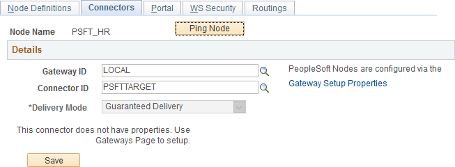
Image: Connectors page showing a default local node
This example illustrates the fields and controls on the Connectors page showing the default local node for the portal system (HCM).
If the remote node will use the shared integration gateway and you did not add this node to the gateway configuration previously, do so now. If you are creating all node definitions before configuring the gateway, then remember the node name for each default local node and enter into the gateway properties later.
Select the Portal page:
Ensure that the correct default portal is selected.
Ensure that a value is defined for the Tools Release field.
Enter values for the Content URI Text field and the Portal URI Text field as are appropriate for the web server port and site on this local system.
Note: When configuring a remote node definition for this node, use the same values as defined on the local system.
For each remote node definition, enter the name of the default local node of the remote system in the Network Node Name field.
Note: Do not set this field on local node definitions.
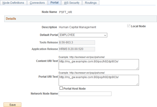
Image: Portal page showing a default local node
This example illustrates the Portal page showing default local node of the portal system (HCM).
Save the node definition.
Repeat steps 2 through 6 for each default local node on each content provider system.
Then, using the values specified in the local node definitions, repeat steps 2 through 6 for each remote definition of each default local node.
Defining Portal Host Nodes
To define portal host nodes on all systems:
-
Access the Configure Unified Navigation navigation collection. (See Configure Unified Navigation Fluid Navigation Collection.)
In the Configure Unified Navigation navigation collection, expand the Single Signon Setup section and select the Configure Node for SSO link to open the Nodes page in the target area.
If the node name already exists in the system, then select that node definition. Otherwise, add a new value for the non-standard node name.
Select the Node Definitions page:
Enter a description for the portal host node.
Verify that the node type is PIA.
For portal host nodes, the Local Node and Active Node check boxes must be selected.
Note: When configuring a remote node definition for this node, only the Active Node check box must be selected.
For portal host nodes, the Authentication Option field value is None.
Enter the default user ID for the node.
Note: When configuring a remote node definition for this node, you must enter the same default user ID. If necessary, create a user profile for this ID.
Select the Connectors page:
Enter the ID for the shared integration gateway in the Gateway ID field.
Note: When configuring a remote node definition for this node, use the same ID.
Enter PSFTTARGET as the connector ID.
Note: If you click the Ping Node button for a remote node that is a portal host node, the following error will be displayed:
Integration Broker Service:
Destination node does not match the local  node. (158,506)
Select the Portal page:
Ensure that the correct default portal is selected.
Ensure that a value is defined for the Tools Release field.
Enter values for the Content URI Text field and the Portal URI Text field as are appropriate for the web server port and site on this local system.
Note: When configuring a remote node definition for this node, use the same values as defined on the local system.
Select the Portal Host Node check box only for a node definition for a remote portal host node.
Note: Do not select this check box on local node definitions.
For each remote node definition, enter the name of the default local node of the remote system in the Network Node Name field.
Note: Do not set this field on local node definitions.
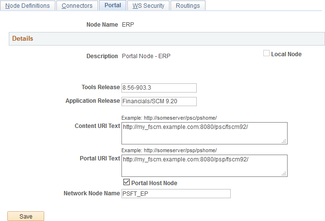
Image: Portal page showing a remote portal host node
This example illustrates the Portal page showing the definition of a remote portal host node (ERP from the FSCM system).
Save the node definition.
Repeat steps 1 through 6 for each portal host node on each content provider system.
Then, using the values specified in the local node definitions, repeat steps 1 through 6 for each remote definition of each portal host node.
After the remote nodes have been defined on each system, all the default local nodes participating in the single signon configuration need to be identified on each system.
To identify the trusted nodes on each system:
Select .
In the Configure Unified Navigation center, expand the Single Signon Setup section and select the Define Trusted Nodes link to open the Single Signon page in the target area.
Add the default local node from each content provider system as a trusted node.
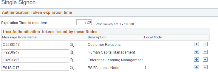
Image: Single Signon page listing all trusted nodes
This example illustrates the Single Signon page listing all trusted default local nodes.
Save the list of trusted nodes.
Select .
Select the Authorized Site page.
Image: Web Profile Configuration - Authorized Site page
This example illustrates the fields and controls on the Web Profile Configuration - Authorized Site page.
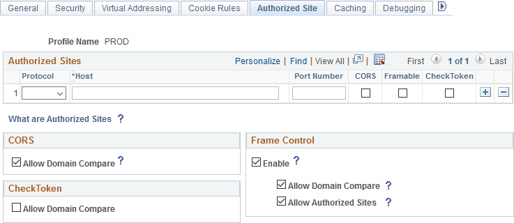
Using the CheckToken settings, add each remote host participating in the single signon configuration, either explicitly, by specifying the host’s domain or subdomain, or by selecting the Allow Domain Compare check box when appropriate.
Save the configuration. Then, stop and restart the web server.
Once content provider nodes have been defined in the portal system, only default local nodes need to be added to the integration network to complete the network configuration.
Note: If you added default local nodes from the content provider systems to the integration network previously, then you will not need to complete this procedure.
See Configuring the Integration Gateway.
To add default local nodes from the content provider systems to the integration network:
-
Access the Configure Unified Navigation navigation collection. (See Configure Unified Navigation Fluid Navigation Collection.)
In the Configure Unified Navigation navigation collection, select the IB Network Status link to open the integration network's Configuration Status page.
Click the Node Network Configured link.
For each remote node that is a default local node, select the check box to make the node in network.
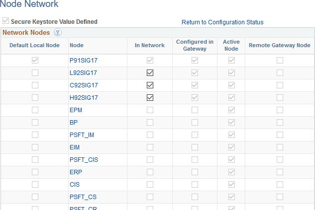
Image: Node Network page showing default local nodes as in network
This example illustrates the Node Network page showing six default local nodes as in-network.
Save the changes to the integration network.