System Architecture Overview
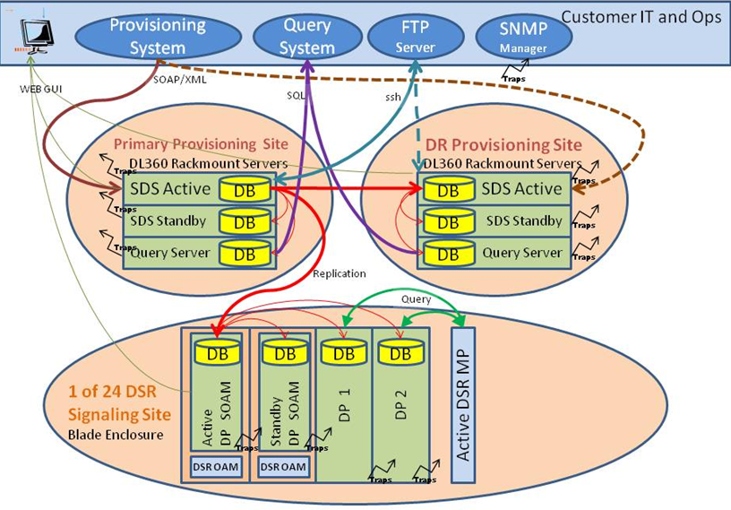
Figure 2-1 provides an overview of the SDS architecture.
Figure 2-1 SDS Architecture Overview

The SDS system consists of a Primary Provisioning Site, a Disaster Recovery (DR) Provisioning Site, and up to 24 Signaling Site servers with redundant data processor Site Operation Administration and Maintenance (SOAM) servers and up to 2 data processing blades. Each provisioning site has an active/standby pair of servers in a High Availability (HA) configuration and a third server configured as a Query server.
The SDS system is built on a platform that provides a variety of services such as site-based GUI, HA capabilities (active/standby switchover and DR switchover), and database functionality (replication, backup, restore).
Every server within the SDS system collects measurements, alarms, and events data. Every server sends its traps directly to the Customer SNMP Manager.
Every server can also collect measurement data. Data processing measurements are sent to the active SOAM server, which sends the measurements from all data processing servers and itself to the Active SDS server on the Primary Provisioning Site. The measurements can be viewed on the GUIs for the active SDS server on the Primary Provisioning Site and the data processing SOAM server on the Signaling Site.