2 vSTP Security Overview
This chapter describes the overview of vSTP security with detailed configurations. The vSTP security features are described as per the following security levels:
MTP Level Security
This section describes the MTP Level security features of vSTP:
MTP Screening
The MTP Screening feature provides a mechanism to screen the incoming calls based on the MTP Screening rules configurations. The MTP screening rule is an entity to configure all the screening rules for a Screen Set.
For more details on MTP Screen Rules configurations, refer to vSTP User's Guide.
SCTP Firewall Support
vSTP achieves network security by utilizing the Linux firewall provided by Oracle Linux distribution that serves as the platform for vSTP software.
vSTP configures firewall rules in the Linux firewall on each server to allow only essential network traffic. The vSTP software is composed of various components providing unique services, and each component is responsible to configure the firewall rules to allow the network traffic destined to and originated from the provided services. While platform services are internal and not configurable in customer deployments, the signaling services are completely configurable at runtime.
Note:
By default, the SCTP Firwall feature remains enabled.Feature Description
The SCTP Firewall feature brings the flexibility and capability in vSTP to dynamically determine and customize the linux firewall on each vSTP-MP server. It allows only the essential network traffic, pertaining to active signaling configurations. The in-bound signaling traffic is accepted by the vSTP application over the configured and enabled connections only. By monitoring the active configuration, this feature determines, which configured connections are enabled. It then configures the Linux Firewall on the vSTP-MP servers to allow the signaling network traffic for those connections only and completely deny the non-signaling network traffic (non-signaling traffic is traffic from internal services i.e. SSH, FTP, HTTP, HTTPS, etc.), thus providing added security to the signaling networks.
Firewall Manager Process
The FMP (Firewall Manager Process) is added to the vSTP MP software. This process manages the Linux firewall (local to the vSTP-MP) by keeping it in sync with the active signaling connection configuration. The signaling firewall is administered (Enabled or Disabled) from SOAM server via the supported user interfaces and will take effect on all the vSTP-MPs in the signaling node. When a connection is enabled or disabled, a configuration change notification is sent by comcol’s data change monitor to FMP, which updates the Linux Firewall rules to allow or disallow the network traffic pertaining to the connection in context.
In addition, the FMP also periodically audits the firewall configuration against the active configuration and automatically corrects any mismatch it finds in the firewall rules against the enabled connection quadruples.
Feature Implementation
- IPSets are used to set up, maintain and inspect the set of IPs in the Linux
kernel. Depending on the type of the set, an IP set may store IP(v4/v6)
addresses, (TCP/UDP) port numbers, IP and MAC address pairs, IP address and port
number pairs and so on.
IPSet are the collection of IP addresses. The format of IPSet is: hash: ip, port
- The hash:ip, port set type uses a hash to store IP address and port number pairs.
- The port number is interpreted together with protocol(default TCP) an d zero protocol number cannot be used.
These IPSets are utilized by IPTables to either ALLOW or RESTRICT IP's to/from the network. IPSets used in vSTP Firewall Enhancement are:- dsrIPv4conns – Stores active connection attributes/connection quadruple from VstpConnections table (local IPv4 address, transport protocol, local port number and remote IPv4 address) .
- dsrIPv4ServicePorts – Stores all the configured protocol and port numbers from VstpConnectionNode table which is dynamically updated.
- IPTables matches and targets referring to sets create references, which protect the given sets in the kernel. A set cannot be destroyed while there is a single reference pointing to it.
Feature Configurations
This section provides procedures to perform the vSTP SCTP Firewall functionality.
The vSTP SCTP Firewall is configured using the vSTP managed objects and vSTP GUI. The MMI API contains details about the URI, an example, and the parameters available for each managed object.
SCTP Firewall Alarms and Measurements
Alarms and Events
The following table lists the alarms or events specific to the SCTP Firewall functionality for vSTP:
| Event ID | Event Name |
|---|---|
| 25607 |
Signaling Firewall is administratively Disabled |
| 25608 |
Abnormal vSTP-MP Firewall |
| 25601 |
DSR Signaling Firewall configuration inconsistency detected |
| 25609 | Firewall Configuration Error encountered |
Troubleshooting
When vSTP SCTP Firewall feature is On, the events specific to this feature are generated. For more information, see SCTP Firewall Alarms and Measurements.
SCCP Level Security
This section describes the Signaling Connection Control Part (SCCP) of of the SS7 protocol.
The Global Title Translation (GTT) feature is designed for SCCP. The GTT feature uses Global Title Address (GTA) information to determine the destination of the MSU. The Translation Type (TT) indicates which GTT table is used to determine the routing to a particular service database. Each GTT table includes the Point Code (PC) of the node containing the service database, the SubSystem Number (SSN) identifying the service database on that node, and a Routing Indicator (RI). The RI determines if further GTTs are required. GTA and TT are contained in the Called Party Address (CdPA) field of the MSU.
The GTT feature changes the destination PC and the origination PC in the routing label. The GTA information is not altered.
Depending on how the GTT data is configured, the GTT may also change the RI, SSN, or the TT in the CdPA. The gray shaded areas in the following tables show the message fields affected by GTT.
Figure 2-1 ANSI MSU (ANSI Message Signal Unit)

Figure 2-2 ITU-I MSU (ITU International Message Signal Unit)

Figure 2-3 14-Bit ITU-N MSU (14-Bit ITU National Message Signal Unit)

Figure 2-4 24-Bit ITU-N MSU (24-Bit ITU National Message Signal Unit)

GTT Routing
The Global Title Translation (GTT) feature is designed for the Signaling Connection Control Part (SCCP) of the SS7 protocol. The routing options described in this section allow you to add translations to parameters, code, and components for additional flexibility in routing a message.
Flexible Linkset Optional Based Routing (FLOBR)
- Linkset based routing routes GTT traffic based on the incoming linkset
- Flexible routing routes GTT traffic based on parameters such as MTP, SCCP, and TCAP in a flexible order on a per translation basis
With the FLOBR feature, you can change the default CdPA GTTSET to point to any GTT set type and find the translation.
FLOBR works based on the following rules:
- When GTT mode is FLOBR CDPA, CDPA fields in the MSU are used for GTT selector search and the GTT set is taken from the CDPA GTT SET Name configured in the selector entry.
- When GTT mode is FLOBR CGPA, CGPA fields in the MSU are used for GTT selector search and the GTT set is taken from the CGPA GTT SET Name configured in the selector entry.
- When GTT hierarchy is FLOBR CDPA and FLOBR CGPA, GTT selectors are searched as defined in 1. If no selector match is found or CDPA GTTSET is not provisioned, GTT selectors are searched as defined in 2.
- When GTT hierarchy is FLOBR CGPA and FLOBR CDPA, GTT selectors are searched as defined in 2. If no selector match is found or CGPA GTTSET is not provisioned, GTT selectors are searched as defined in 1.
- If GTT selectors are not found as specified in 1, 2, 3 or 4, then vSTP considers this a translation failure.
- You can provision a fallback option for
each translation in FLOBR to tell it how to route an MSU under the following
conditions:
- Routing when a search fails
- Routing when the same GTT set name is referred to more than once
- Limiting the number of database searches to seven (7)
- When a fallback option is set to No, the GTT fails and the MSU is discarded.
- When a fallback option is set to Yes, the GTT performs based on the last matched entry.
GTT Action Feature
The Global Title Translation (GTT) action feature performs additional actions on the incoming/translated Message Signaling Unit (MSU) coming from the GTT. Configure GTT Action, GTT Action Set, and GTA Managed Object (MO) to use these as optional features.
vSTP supports the following types of GTT actions:
- Discard
- UDTS
- TCAP Error
- Forward
- Duplicate
- SFAPP
- SFTHROT
- SCPVAL
Discard
The Discard GTT action discards incoming MSU.
UDTS
The Unit Data Service (UDTS) GTT action marks the MSU as discarded and an error response is sent back with an udts error code.
TCAP Error
The Transaction Capabilities Application Part (TCAP) Error GTT action marks the MSU as discarded and an error response is sent back with an tcap error code.
Forward
The Forward GTT action forwards the incoming/translated MSU to a specified point code per configuration. The MSU does not forward to translated point code.
If the Forward GTT action fails, then default actions are performed per configuration:
- Fallback means forward the MSU to translated point code
- Discard an incoming MSU
- Send a UDTS response with an udts error code per configuration
- Send a TCAP error response with an tcap error code per configuration
Duplicate
The Duplicate action sends a copy of incoming/translated MSU to a specified point code per configuration. The MSU does sent to translated as well as duplicate point code.
SFAPP
The Stateful Application (SFAPP) action validates the messages coming in for a subscriber by validating them against the Visitor Location Register (VLR).
SFTHROT
The GTT Throttle action is part of SS7 security firewall. It provides support for Egress throttling of GTT messages in vSTP. For more details, see GTT Throttle Action.
SCPVAL
The SCPVAL GTT action along with relevant parameters performs the validation on MAP parameters by comparing the SCCP and MAP digits. For more details see, GTT SCPVAL Action.
GTT Throttle Action
The GTT Throttle is a GTT Action that performs the Egress throttling of GTT messages in vSTP. This action is part of SS7 security firewall. GTT Throttle feature provides the support for Egress throttling of individual messages and group of GTT messages in vSTP.
- Enabling the
SFTHROTaction for Group Throttling - Enabling the
Indv_Throtaction for individual Throttling
Group Throttling
The Group GTT Throttle Feature provides Egress Throttling of GTT messages with
SFTHROT GTT Action. For each GTT Action, user provides
threshold as the maximum number of MSUs hitting the GTT action per second. The SMS
framework to accumulates the total number of MSU count per SFTHROT action.
When an MSU hits a GTT action of the type SFTHROT, the MSU count of that action is updated. SMS framework accumulates the total number of messages per SFTHROT action on MP Leader and sends cumulative count to all MPs across site. If the cumulative count of messages crosses the provisioned threshold, MPs starts throttling that messages. Any MSU hitting the GTT action gets discarded and the MSU count of that messages is not increased due to throttling, due to which cumulative value decreases in next sliding window. Once the cumulative value is lower than the configured threshold, the messages are allowd.
Note:
Individual Throttling
The Individual GTT Throttling Feature provides Egress Throttling of GTT message with
Indv_Throt GTT Action. For each Indv_Throt GTT
Action, user provides threshold as maximum number of MSUs hitting the GTT action per
second per GTA. The SMS framework is used to accumulate the total number of MSU
count of Indv_Throt action.
Indv_Throt, the MSU count
of that GTA gets updated. The SMS framework accumulates the total number of
messages on MP Leader and sends cumulative count to all MPs across site. If the
cumulative count of GTA crosses the provisioned threshold, MPs start throttling that
GTA. Any MSU hitting that GTA gets discarded and the MSU count of that message is
not increased due to throttling, due to which cumulative value decreases in next
sliding window. Once the cumulative value is lower than the configured threshold,
the messages are allowed.
Note:
Individual throttling supports 100K GTA.Workflow for GTT Throttle Action
The GTT Throttle action works based on the following rules:
-
When an MSU hits a GTT action of the type SFTHROT, the MSU count of that action gets updated. For Indv_Throt, the MSU count of the GTA is updated.
Note:
The Shared Metric Service (SMS) framework is used to accumulate the total number of MSU count per SFTHROT action. -
The MSU count is updated only on the Message Processor (MP) on which the message is received for that action. On the other hand, the Threshold configuration for SFTHROT action is across the MPs.
Note:
For each GTT Action, user provisions a threshold value that is the maximum number of MSUs hitting the GTT action per second.
-
Two sysmetrics are registered. The first is for MSU count per MP and second one for cumulative MSU count across the site.
-
Aggregation of the MSU count from all the MPs is done by the MP Leader. There is only one MP leader across the site. It performs the aggregation of MSU counts. Rest of the MPs across the site are known as followers.
-
Whenever a message comes to any MP, it will increment the sysmetric count of that MP known as local sysmetric count. All the follower MPs will send the local sysmetric count data to the MP Leader to get the aggregated value of that action.
-
The MP Leader receives the data from all the other MPs including it's own local sysmetric count. It will do the aggregation and broadcast the cumulative count to all the MPs.
-
The SMS framework is used to send local sysmetric count to MP leader and receive the aggregated sysmetric count from it. The aggregation of the count is taken care by SMS framework hence, any degradation in SMS service will impact the feature.
-
When GTT message is received for SFTHROT/Indv_Throt action, then the aggregated sysmetric count is compared with the configured threshold value for that action:
- If the aggregated sysmetric count value is lesser than the configured threshold value, then the message is allowed and the local sysmetric count value is increased by 1.
- If the aggregated sysmetric
count value is more than the configured threshold value, then the local
sysmetric count value does not get increased due to throttling. The GTT
message is discarded, discard measurement is pegged for that action, and
an alarm is raised.
- The alarm gets cleared once the aggregated sysmetric count drops below 90% of the configured threshold value.
- As there is no local sysmetric is pegged, the aggregated count will be decreased in next sliding window. Convergence time is 2 sec.
- Once the cumulative value drops below the configured threshold, it will allow the GTT messages for that action and the local sysmetric count will be increased.
Note:
For GTT Throttle action, an error margin of +2% to -2% of the provisioned threshold value must be considered. The error margin depends on the cloud infrastructure load & burst pattern of incoming traffic.
The following figure shows the process flow for GTT Throttle action:
Figure 2-5 Process Flow of GTT Throttle Action

MMI Managed Objects for GTT Throttle Action
MMI information associated with GTT Throttle action is accessed from a DSR NOAM or SOAM from .
Once the MMI API Guide displays, use the application navigation to locate specific vSTP managed object information.
Table 2-1 GTT Throttle Action Managed Objects and Supported Operations
| Managed Object Name | Supported Operations |
|---|---|
| gttactions | Insert, Update, Delete |
| gttactionsets | Insert, Update, Delete |
gttactions - Insert, Update, Delete
- For SFTHROT Action Type (Group Throttling)
Create a file with the following content:
$ cat gttaction.txt
{
        "act": "Sfthrot",
        "actid": "GA1",
        "defactid": "fallback",
         "threshold": 99

       }
Note:
The threshold is mandatory parameter for SFTHROT action type. Range is 1 to 4294967295. Modification is allowed for threshold.
Execute the following command on an active SOAM to insert:/vstp/gttactions -v POST -r /<Absolute path>/<Fiename>Example output:/vstp/gttactions -v POST -r gttaction.txt { "act": "Sfthrot", "actid": "GA1", "defactid": "fallback", "taIndex": 0, "threshold": 36 } - For INDV_THROT Action Type (Individual Throttling)
Create a file with the following content:
$ cat gttaction.txt
          {
            "act": "Indvthrot",
            "actid": "indv1",
            "defactid": "fallback",
            "gtaLength": 10,
            "threshold": 35
        }
Note:
-
vSTP supports a total of 100K GTA while provisioning GTA entries with action set having action type as INDV_THROT. This is the combined limit for all the Indv_Throt actions.
-
The threshold and gtaLength are mandatory parameters for INDV_THROT action type. Range is 1 to 4294967295. Modification is allowed for threshold.
-
If no action type is selected, then the threshold value remains 1, by default.
Execute the following command on an active SOAM to insert:/vstp/gttactions -v POST -r /<Absolute path>/<Fiename>Example output:/vstp/gttactions -v POST -r gttaction.txt { "act": "Indvthrot", "actid": "indv1", "defactid": "fallback", "gtaLength": 10, "taIndex": 65535, "threshold": 3 } -
Note:
vSTP supports a total of 100K GTA while provisioning GTA entries with action set having action type as INDV_THROT. This is the combined limit for all the Indv_Throt actions.
gttactionsets - Insert, Update, Delete
Create a file with the following content:
{
    "actsn": "actset1",
    "actid1": "Act1“
}
Note:
-
Maximum one SFTHROT action is allowed to be provisioned per VstpGTTActionSet entry.
- Maximum one INDV_THROT action is allowed to be provisioned per VstpGTTActionSet entry.
- If both INDV_THROT and SFTHROT actions are selected, INDV_THROT action gets the first preference and it is followed by the SFTHROT action. If INDV_THROT action is not selected, then SFTHROT gets the first preference.
/vstp/gttactionsets -v POST -r /<Absolute path>/<File Name> /vstp/gttactionsets -v POST -r /tmp/ActSet1
{
"data": true,
"links": {},
"messages": [],
"status": true
}
/vstp/gttactionsets -v PUT -r /<Absolute path>/<File Name>
 /vstp/gttactionsets -v PUT -r /tmp/actset1
{
 "data": true,
 "links": {},
 "messages": [],
 "status": true
}
/vstp/gttactionsets/<Set Name> -v DELETE
Example output:
 /vstp/gttactionsets/Set1 -v DELETE
No output returned by URI: https://localhost/mmi/dsr/v3.0/vstp/gttactionsets/Set1? for 'DELETE' operation
Execute the following command to display:
/vstp/gttactionsets
Example output:
  /vstp/gttactionsets
{
 "data": [
{
    "actsn": "actset1",
    "actid1": "Act1“
}
],
"links": {},
    "messages": [],
    "status": true
}
GTT Throttle Measurements
Measurements
| Measurement ID | Measurement Name |
|---|---|
| 21723 | VstpThrottleActionMsgDiscard |
| VstpThrottleActionMsgReceived |
For more details related to measurements, refer to Measurement Reference document.
Dependencies
The GTT Throttle action support for vSTP has no dependency on any other vSTP operation.
Points To Consider
- There is error margin of the provisioned threshold value depending on the cloud infrastructure load & burst pattern of incoming traffic.
- The error margin for Individual Throttling is greater than the Group Throttling
as Aggregation timeout for
Indv_Throtis 200 ms whereas, the Aggregation timeout for Group Throttling is 10 ms.
GTT SCPVAL Action
The SCCP MAP Validation (SCPVAL) is a GTT Action that performs validation check on the of vSTP map parameters. This action is part of SS7 security firewall.
For example, in vSTP few of the map parameters must be same as either SCCP CdPA or CgPA. The GTT SCPVAL action do this validation check with a comparison between SCCP parameters and the map digits.
Note:
- MO-FSM (MAP version 2 or 3)
- MT-FSM (MAP version 3)
The SCPVAL action has the following set of parameters to execute the functionality:
| Parameter Name | Description | Value |
|---|---|---|
| SPRM | Define the SCCP parameter value. It is a mandatory parameter. | The value can be either of the following:
|
| TPRM | Define the TCAP parameter value. It is a mandatory parameter. | The value can be either of the following:
|
| NDGT | Specifies the number of digits that needs to be matched between SCCP parameter and MAP parameter. This is an optional parameter. |
Value:
Default value: All |
| USEICMSG | Specifies whether to retrieve the data for comparison from the original message or from the post-GTT message. |
The value can be either of the following: OFF: Use original message as received by the SCCP. ON: Use post-GTT message that is, after possible GTT translation/modification data has been applied. |
| UIMREQD | Specifies if an event has be generated in case of GTT action failure. |
The value can be either of the following:
|
| DEFACTID | Defines the default action that is performed when SCPVAL GTT action fails. | String value |
Workflow for SCPVAL Action
The following flowchart describes the implementation of MAP SCCP validation:
Figure 2-6 SCCP MAP Validation Flowchart

MMI Managed Objects for SCPVAL
MMI information associated with SCPVAL action is accessed from a DSR NOAM or SOAM from .
Once the MMI API Guide displays, use the application navigation to locate specific vSTP managed object information.
Table 2-2 vSTP SCPVAL Managed Objects and Supported Operations
| Managed Object Name | Supported Operations |
|---|---|
| gttactions | Insert, Update, Delete |
| gttactionsets | Insert, Update, Delete |
gttactions - Insert, Update, Delete
Create a file with the following content:
{
 "act": "Scpval",
 "actid": "Act1",
 "defactid": "fallback",
 "ndgt": "2",
 "sprm": "Cdgta",
 "tprm": "Smrpda",
 "uimreqd": "true"
 "useicmsg": "true"
}
/vstp/gttactions -v POST -r /<Absolute path>/<File Name> /vstp/gttactions -v POST -r /tmp/GttAct1
{
"data": true,
"links": {},
"messages": [],
"status": true
}
/vstp/gttactions -v PUT -r /<Absolute path>/<File Name>
 /vstp/gttactions -v PUT -r /tmp/GttAct1
{
 "data": true,
 "links": {},
 "messages": [],
 "status": true
}
/vstp/gttactions/<Rule Name> -v DELETE
Example output:
 /vstp/gttactions/Act1 -v DELETE
No output returned by URI: https://localhost/mmi/dsr/v3.0/vstp/gttactions/Act1? for 'DELETE' operation
Execute the following command to display:
/vstp/gttactions
Example output:
  /vstp/gttactions
{
 "data": [
{
        "act": "Scpval",
        "actid": "Act1",
        "defactid": "fallback",
        "ndgt": "2",
        "sprm": "Cdgta",
        "tprm": "Smrpda",
								"uimreqd": true,
        "useicmsg": true
}
   					 ],
   				 "links": {},
    				"messages": [],
    				"status": true
}
gttactionsets - Insert, Update, Delete
Create a file with the following content:
{
    "actsn": "actset1",
    "actid1": "Act1“
}
/vstp/gttactionsets -v POST -r /<Absolute path>/<File Name> /vstp/gttactionsets -v POST -r /tmp/ActSet1
{
"data": true,
"links": {},
"messages": [],
"status": true
}
/vstp/gttactionsets -v PUT -r /<Absolute path>/<File Name>
 /vstp/gttactionsets -v PUT -r /tmp/actset1
{
 "data": true,
 "links": {},
 "messages": [],
 "status": true
}
/vstp/gttactionsets/<Set Name> -v DELETE
Example output:
 /vstp/gttactionsets/Set1 -v DELETE
No output returned by URI: https://localhost/mmi/dsr/v3.0/vstp/gttactionsets/Set1? for 'DELETE' operation
Execute the following command to display:
/vstp/gttactionsets
Example output:
  /vstp/gttactionsets
{
 "data": [
{
    "actsn": "actset1",
    "actid1": "Act1“
}
],
"links": {},
    "messages": [],
    "status": true
}
SCPVAL Alarms and Measurements
Alarms and Events
The following table lists the Alarms and Events specific to SCPVAL:
| Alarm/ Event ID | Name |
|---|---|
| 70278 | GTT Action Failed |
For more details related to Alarms and Events, refer to Alarms and KPIs Reference document.
Measurements
| Measurement ID | Measurement Name |
|---|---|
| 21776 | VstpCdpaGttActScpvalTotal |
| 21777 | VstpCdpaGttActScpvalDiscard |
| 21778 | VstpCdpaGttActScpvalNotApplied |
| 21779 | VstpCgpaGttActScpvalTotal |
| 21780 | VstpCgpaGttActScpvalDiscard |
| 21781 | VstpCgpaGttActScpvalNotApplied |
For more details related to measurements, refer to Measurement Reference document.
Troubleshooting
The following are the troubleshooting scenarios for SCPVAL action:
-
If an incoming MSU successfully passes SCPVAL CdPA GTT action, then the VstpCdpaGttActScpvalTotal measurement will be pegged on a per Linkset basis.
-
If validation was not applied by SCPVAL CdPA GTT action on an incoming message, VstpCdpaGttActScpvalNotApplied will be pegged on a per Linkset basis.
-
If incoming MSU is discarded by SCPVAL CdPA GTT action, then VstpCdpaGttActScpvalDiscard measurement will be pegged on a per Linkset basis.
-
If validation was not applied by SCPVAL CgPA GTT action on an incoming message, VstpCgpaGttActScpvalNotApplied will be pegged on a per Linkset basis .
-
If an incoming MSU successfully passes SCPVAL CgPA GTT action , then VstpCgpaGttActScpvalTotal measurement will be pegged on a per Linkset basis.
-
If incoming MSU is discarded by SCPVAL CgPA GTT action, then VstpCgpaGttActScpvalDiscard measurement will be pegged on a per Linkset basis.
-
When anyone of the GTT Action (i.e. DUPLICATE, FORWARD, TCAP ERROR, SCPVAL) fails and UIMREQD is set to ON, then event 70278 GTT Action Failed will be generated. It contains error cause with SCCP and TCAP details, GTT Action set name and linkset ID.
-
If any of the above statement fails as per given scenarios, then verify the configuration. In case the issue persistes, contact Oracle Support.
MTP Based GTT with Screening Action
vSTP supports the MTP based GTT with screening actions feature.
This feature provides the capability of performing SCCP services on MTP-routed messages. Therefore, allows the operator to perform GTT and GTT Actions on MTP Routed MSUs, similar to GTT handling for GT Routed MSUs.
Note:
This feature supports the screening based on MTP3 layer parameters only.MTP Based GTT Feature Configuration
The MTP based GTT with Screening Action is performed if the service handling results in Fall through to GTT or if GTT Required option is ON for Service Relayed MSU.
The following system-wide options are used to configure this functionality:
-
MTP Routed GTT
The MTP Routed GTT (mtprgtt) option is used for MTP Routed GTT functionality as follows:-
If option = OFF, then GTT shall not be performed on MTP Routed MSUs.
-
If option = Use MTP Point codes, then GTT shall be performed on MTP Routed MSU, SCCP Portion shall be updated based on translation entry but MSU shall be sent to Original DPC (and not to translated DPC).
-
If option = Full GTT, then GTT shall be performed on MTP Routed MSU, SCCP Portion as well as MTP Portion shall be updated based on translation results.
-
-
MTP Routed GTT fallback
The MTP Routed GTT fallback (mtprgttfallbk) option is used for error handling to be performed in case of GTT failure for MTP routed MSUs. It has the following values:
-
If option = GTT failure, then MSU will be discarded with appropriate UIM. UDTS will be sent to originator and measurements shall be pegged as done for GT routed messages.
-
If option = Fall back to MTP routing, then MSU (with translation/modification/routing data from UDR-related service) shall be MTP routed.
-
The support for the following features is required for the functionality of MTP based GTT:
-
SCCP Stop Action: provide a means for the operator to specify SCCP Stop Action in the MTP Screening Rules, to allow the MTP processing to fall through to GTT on non-discarded MSUs.
-
XLAT = NONE: provide a means for the operator to specify GTT Translation Type = NONE.
-
•
GTT SET = DPC: A new GTT set, DPC (with set type dpc) shall be supported. The provisioning and behavior of the DPC Translations shall be same as OPC Translations. However, DPC GTT set cannot be used as secondary optional set (i.e. DPC GTT set cannot be assigned to OPCSN parameter in translation entry). The DPC GTT set type can be searched only when the GTT hierarchy is FLOBR specific.
MMI Managed Objects for MTP Based GTT
MMI information associated with MTP Based GTT Support is accessed from a DSR NOAM or SOAM from .
Once the MMI API Guide displays, use the application navigation to locate specific vSTP managed object information.
The following table lists the managed objects and operations supported for vSTP MTP Based GTT feature:
Table 2-3 vSTP MTP Based GTT Managed Objects and Supported Operations
| Managed Object Name | Supported Operations |
|---|---|
| sccpoptions | Update |
| mtpscreeningrules | Insert, Update, Delete |
sccpoptions - Display
The Signaling Connection Control Part (SCCP) Options are those configuration values that govern the overall SCCP functionality . There is a single instance of this resource, which contains each of the individual options that can be retrieved and set. Because there is no collection of instances, there is no collection GET action. No new SCCP Options resource can be created, so there is no POST action, and the single instance cannot be removed, so there is no DELETE action. The single instance GET is used to retrieve the options, and PUT is used to update one or more values within the set of options. A name for this single, non- deletable instance is neither required nor expected.
{
       "class1seq": "Disabled",
        "dfltfallback": false,
        "dfltgttmode": "Cd",
        "mtprgtt": "Fullgtt",
        "mtprgttfallback": "Gttfail",
        "tgtt0": "None",
        "tgtt1": "None",
        "tgttudtkey": "Mtp",
        "tgttxudtkey": "Mtp"
}
mtpscreeningrules - Insert, Update, Delete
{
           "actionSccp": true,
            "area": "7",
            "nsfi": "Stop",
            "ruleName": "rule5",
            "scrRuleGroupName": "scr5",
            "scrRuleGroupType": "Opc",
            "signalingPointId": "3",
            "zone": "3"
}
MTP Based GTT Alarms and Measurements
Alarms and Events
No specific Alarms and Events are generated for MTP based GTT.
Measurements
| Measurement ID | Measurement Name |
|---|---|
| 21304 | VstpRxMSUMtpRoutedSccp |
For more details related to measurements, refer to Measurement Reference Guide.
Troubleshooting
In case of the error scenarios, the measurements specific to MTP based GTT feature are pegged. For information related to MTP based GTT measurements, see MTP Based GTT Alarms and Measurements.
GTT Action Set Test Mode
The service providers across the world undertake security monitoring projects that requires blocking of illegitimate traffic in SS7 networks. It is an umbrella of all the interconnect traffic and needs to be monitored closely before any traffic is blocked by an operator.
Unauthorized traffic can be blocked by applying certain sets of rules. On the other hand, it is equally imperative that legitimate or revenue generating traffic is not discarded by the framework.
vSTP enables the operators to block the unauthorized traffic using the GTT Action Set Test Mode functionality. This feature provides a detection mode to raise an event for the MSUs that encounters that particular GTT action and skips all the other actions included in that set. This helps to identify all the traffic that is discarded, copied, or forwarded once the rule is made active.
In case of an impact on any legitimate traffic, the rules can be changed accordingly.
Feature Configurations
This section provides procedures to configure the GTT Action Set Test mode functionality.
GTT Action Set Test mode is configured using the vSTP managed objects and vSTP GUI. The MMI API contains details about the URI, an example, and the parameters available for each managed object.
MMI Managed Objects for GTT Action Set Test Mode
MMI information associated with GTT Action Set Test Mode support is accessed from a DSR NOAM or SOAM from .
Once the MMI API Guide gets opened, use the application navigation to locate specific vSTP managed object information.
The following table lists the managed objects and operations supported for GTT Action Set Test Mode support:
Table 2-4 GTT Action Set Test Mode support Managed Objects and Supported Operations
| Managed Object Name | Supported Operations |
|---|---|
| gttactionset | Insert, Update, Delete |
gttactionset - Insert, Update, Delete
{
            "actid1": "set1",
            "actid2": "set2",
            "actsn": “ActSet1",
            "testMode": "On"
        }
Execute the following command on Active SOAM to insert the action set:
/vstp/gttactionsets -v POST -r /<Absolute path>/<File Name> Sample Output:
{
"data": true,
"links": {},
"messages": [],
"status": true
}/vstp/gttactionsetsSample Output:
{
 "data": [
{
            "actid1": "set1",
            "actid2": "set2",
            "actsn": “ActSet1",
            "testMode": "On“
}
],
"links": {},
    "messages": [],
    "status": true
}
GUI Configurations
The GTT Action Set Test Mode can be configured from Active System OAM (SOAM).
On the Active System OAM (SOAM), select VSTP Configuration GTT Action Sets.
Configure the parameters on the GTT Action Sets page.
For more details on GTT Action Sets configurations, refer to Diameter Signaling Router Virtual Signaling Transfer Point User's Guide .
GTT Action Set Test Mode Alarms and Measurements
Alarms and Events
| Event ID | Event Name |
|---|---|
| 70445 |
Vstp GTT Action Test Mode On |
For more details related to measurements, refer to Alarms and KPIs Reference document.
Measurements
There are no measurements specific to the GTT Action Set Test Mode functionality.
TCAP Level Security
This section describes the TCAP Level security features of vSTP:
TCAP Opcode Based Routing (TOBR)
TOBR provides vSTP with the ability to route messages based on its operation codes. With the TOBR feature, vSTP considers the following information contained in TCAP portion of messages for performing GTT.
- ITU Messages
- Message/Package type
- Application context name
- Operation code
- ANSI Messages
- Package type
- Operation code family
- Operation code specifier
- Message Type support by TOBR for ITU and ANSI
- ITU TCAP
- Begin
- Continue
- End
- Abort
- Unidirectional
- ANSI TCAP
- Unidirectional
- QueryWithPermission
- QueryWithoutPermission
- Response
- ConversationWithPermission
- ConversationWithoutPermission
- Abort
TOBR works based on the following rules:
- If the message/package type is NOT one of those mentioned, vSTP treats it as an unknown message type and does not proceed with the decoding.
- vSTP attempts to decode the TCAP portion of all UDT/UDTS/Unsegmented XUDT/Unsegmented XUDTS queries coming to the SCCP layer for GTT.
- If decoding fails, the message still undergoes GTT using some default values for the TCAP data that denote their absence in the message.
- ACN is used for all supported ITU TCAP messages except ABORT. No attempt to retrieve ACN is made for Abort messages. All other supported messages may have a Dialog portion containing Dialogue Request/Unidirectional Dialogue/Dialogue Response PDU, from which the ACN is retrieved. If no Dialog portion is detected, then ACN is assumed to be NONE.
- TOBR attempts to find the Operation Code (Opcode) in all supported ITU TCAP messages except ABORT. These messages must contain Invoke or Return Result (Last or Not Last) as the first component. If not, Opcode is assumed to be NONE.
- TOBR attempts to find the Operation Family and Specifier in all supported ANSI TCAP messages (except ABORT) containing an INVOKE component. For all other messages, Family and Opcode are assumed to be NONE.
vSTP Multi Component Message Security
Along with TOBR (TCAP OpCode Based Routing), vSTP provides the capability to decode all the components of a TCAP message. The multi component message security functionality checks for the presence of multiple MAP operations in the message for which the MSU is processed under the GTTSet of type OPCODE. The highest priority translation is selected for the final translation of MSU.
Feature Description
-
A checkmulcomp parameter in VstpSccpGTTSet of type OPCODE indicates that MSUs being processed under the respective set will check for the presence of multiple MAP operations in the same message and will do a translation lookup from more than one component in the MAP portion of the message to find matching translation.
-
In addition, every translation of OPCODE GTTSet has a configurable parameter alwmulcomp. This parameter checks if the respective opcode in the MSU can be allowed to take part in TCAP Multicomponent Checking.
-
The configurable parameter prio available in GTA of OPCODE GTTSet helps in selecting GTA for component in the MSU when more than one key has successful match in GTTSet . The lower value being the highest priority GTA. The MSUs belonging to Opcode VstpSCCPGTTSet, where TCAP MulComp feature is applicable, if the number of components are greater than three, then the packet is discarded.
- Every MAP operation in the message forms a separate key for lookup in the OPCODE GTTSet.
- All the keys are searched in the GTTSet. If there is only one successful lookup, then TOBR functionality is executed.
- If more than one key has a successful match in the GTTSet, then the translation with higher priority number is chosen for further TOBR processing.
- If more than one key matches the translation, whose priority number is equal, then the translation matching the component that occurs first in the message is chosen for further processing.
- The TCAP message component, which is selected (based on translation found and priority), is used for picking other parameters for MAP based routing or for SCPVAL & other GTT Action.
- TCAP Multiple Components supports both ANSI and ITU TCAP messages.
- In case MSU has multiple components, with any of the component having not allowed fields in its translation, then the packet is discarded.
The following figure describes the work flow:

Feature Configurations
This section provides procedures to perform the vSTP Multi Component Message Security functionality.
The SMulti Component Message Security is configured using the vSTP managed objects and vSTP GUI. The MMI API contains details about the URI, an example, and the parameters available for each managed object.
MMI Managed Objects for Multi Component Message Security Support
MMI information associated with Multi Component Message Security support is accessed from a DSR NOAM or SOAM from .
Once the MMI API Guide gets opened, use the application navigation to locate specific vSTP managed object information.
The following table lists the managed objects and operations supported for Multi Component Message Security support:
| Managed Object Name | Supported Actions |
|---|---|
| GTT Sets | Insert, Update, Delete |
| Global Title Addresses | Insert, Update, Delete |
gttset - Insert, Update, Delete
{
            "checkmulcomp": “Yes",
            "domain": "Ansi",
            "gttSetType": "Opcode",
            "name": “Set1"
      }
Execute the following command on Active SOAM to insert the data:
/vstp/gttsets -v POST -r <filename>.jsonSample Output:
    {
            "checkmulcomp": “Yes",
            "configurationLevel": "1",
            "domain": "Ansi",
            "gttSetType": "Opcode",
            "name": "set1"
      }
Note:
/vstp/gttsets/vstp/interfacemappings/{Name}globaltitleaddress - Insert, Update, Delete
  {
            "alwmulcomp": "No",
            "ccgt": false,
            "cgGtmod": false,
            "cgpcaction": "Dflt",
            "fallback": "Sysdflt",
            "family": "46",
            "gttSetName": "set1",
            "opcode": "99",
            "pkgtype": "Any",
            "prio": 1024,
            "translateIndicator": "None"
        }
Execute the following command on Active SOAM to insert the data:
/vstp/globaltitleaddresses -v POST –r <filename>.json
Sample Output:
{
            "alwmulcomp": "No",
            "ccgt": false,
            "cgGtmod": false,
            "cgpcaction": "Dflt",
            "configurationLevel": "29",
            "fallback": "Sysdflt",
            "family": "46",
            "gttSetName": "set1",
            "opcode": "99",
            "pkgtype": "Any",
            "prio": 1024,
            "translateIndicator": "None",
            "uniqueIdentifier": "65b47059-0bb6-4fc1-adcd-f72145eff04f"
        }
GUI Configurations for Multi Component Message Security Support
The Multi Component Message Security functionality can be configured from Active System OAM (SOAM). Select VSTP page.
- GTT Sets
- Global Title Addresses
For more information, see GUI Configuration in Oracle Communications vSTP User's Guide.
Multi Component Message Security Alarms and Measurements
Alarms and Events
The following table lists the alarms or events specific to the Multi Component Message Security functionality for vSTP:
| Event ID | Event Name |
|---|---|
| 70441 |
vstpTobrDupOpcodeFoundDiscard |
| 70443 |
vstpTobrMulCompTransNaDiscard |
| 70444 | vstpTobrMulCompMaxcompExceeded |
For more details related to measurements, refer to Diameter Signaling Router Alarms and KPIs Reference.
Measurements
The following table lists the measurements specific to the Multi Component Message Security functionality for vSTP:
| Measurement ID | Measurement Name |
|---|---|
| 22172 | VstpMSUTmulComp |
| 22173 | VstpMSUTmulCompGtaNa |
| 22174 | VstpMSUTmulCompMaxExc |
For more details related to measurements, refer to Diameter Signaling Router Measurement Reference.
Troubleshooting
In case of the error scenarios, the measurements specific to Multi Component Message Security feature are pegged. For information related to Multi Component Message Security measurements, see Multi Component Message Security Alarms and Measurements.
vSTP TCAP Decoding
The vSTP TCAP Decoding feature allows users to filter the messages, which have additional octets in TCAP layer.
The basic encoding rules often make it possible to encode same values in multiple ways. Therefore, an increase in the number of octets used for encoding an integer is possible. For example encoding in MAP Operation Code prepends 0x00 octets. Similarly, an increase is possible in the number of octets used for encoding an object identifier by pre-pending 0x80 octets to individual sub-identifier octets.
Both of the above scenarios are not allowed as per the security specifications. vSTP discards such messages using the the TCAP Decoding functionality.
Feature Description
The TCAP Decoding feature is applicable for ITU messages.
The tcapErrorDiscard parameter in SCCPOPTIONS table is used to enable the feature.
In the scenario, when MSU is discarded, the VstpTcapDecodeErr event is generated. No UDTS is generated when MSUs are discarded.
TCAP Decoding Error Scenario
- A valid opcode tag is present and opcode length is not equal to one
- ACN and ACN object identifier tags are present but ACN length is either zero or greater than 7
- Invalid length in Transaction portion
- Invalid length in dialog portion
- Invalid length in component portion
- TCAP portion is beyond the last byte of the message as specified by SCCP
Feature Configuration
This section provides procedures to configure the TCAP Decoding feature. The feature requires the vSTP managed objects. The MMI API contains details about the URI, an example, and the parameters available for each managed object.
MMI Managed Objects for TCAP Decoding
MMI information associated with TCAP Decoding support is accessed from a DSR NOAM or SOAM from .
Once the MMI API Guide gets opened, use the application navigation to locate specific vSTP managed object information.
The following table lists the managed objects and operations supported for TCAP Decoding support:
Table 2-5 TCAP Decoding support Managed Objects and Supported Operations
| Managed Object Name | Supported Operations |
|---|---|
| sccpoptions | Display, Update |
sccpoptions
For this feature, the tcapErrorDiscard parameter is added to the sccpoptions MO.
- OFF: TCAP Decoding feature is OFF. This is the default value.
- ON: TCAP Decoding feature is ON.
The example output for Display of sccpoptions MO:
{
        "allowedFirstSegLen": 0,
        "alwMsgDuringRsmblyErr": false,
        "class1seq": "Disabled",
        "dfltfallback": false,
        "dfltgttmode": "Cd",
        "isSegXUDTfeatureEnable": false,
        "mtprgtt": "Off",
        "mtprgttfallback": "Mtproute",
        "reassemblyTimerDurationAnsi": 5000,
        "reassemblyTimerDurationItu": 10000,
        "segmentedMSULength": 200,
        "smsDelivery": "Off",
        "smsOrigination": "Off",
        "smsTermination": "Off",
	  "tcapErrorDiscard": "On",
        "tgtt0": "None",
        "tgtt1": "None",
        "tgttudtkey": "Mtp",
        "tgttxudtkey": "Mtp",
        "travelVelocity": 700
}
Alarms and Measureents
Alarms and Events
The following table lists the Alarms and Events specific to the TCAP Decoding support for vSTP:
Table 2-6 TCAP Decoding Alarms
| Alarm/ Event ID | Name |
|---|---|
| 70457 | VstpTcapDecodeErr |
For more details related to Alarms and Events, refer to Alarms and KPIs Reference document.
Measurements
There are no measurements specific to the TCAP Decoding functionality. However, the existing vSTP measurements are pegged during the TCAP decoding operations.
MAP Level Security
This section describes the MAP Level security features of vSTP:
Map Based Routing (MBR)
MBR provides vSTP with the ability to route messages based on its MAP components. This can be done by using either IMSI or MSISDN GTT set types, which are linked by OPCODE set type.
MBR works based on the following rules:
- TCAP package types BEGIN, CONTINUE, and END are supported for MAP based routing, so OPTSN with one of the MAP GTT set types are allowed to be provisioned for TOBR GTA entries that have "pkgtype" as BGN, CNT, or END.
- When an MSU is processed by the TOBR GTT translation with the OPTSN as one of these new set types, vSTP decodes the TCAP part and extracts the required TCAP parameter from the MSU. The digits in this parameter are used as the key to search for the translation in the GTT set.
- If Dialogue Portion is present in the
message, pick the last byte of the ACN.
Note:
MBR does not validate if the MAP operation is supported with the ACN in the message; it is only decoding the last byte of the ACN to determine the MAP version. - If Dialogue Portion is not present, the MAP version provisioned with the Opcode translation is used as the MAP version.
Stateful Application Feature
SS7 Firewall - Stateful Applications (SFAPP) allows vSTP to validate the messages coming in for a subscriber by validating them against the Visitor Location Register (VLR). The last seen details of the subscriber can be fetched from the Home Location Register (HLR). Once the HLR provides a validity of the new VLR, vSTP then allows the message into the network. If the message is not validated, it is handled as per configuration (either silent discard, fallback, or respond with error).
For detailed information about this feature, refer to vSTP SS7 Security User's Guide.
Supported MAP Operations
The following MAP Operations are supported by the Stateful Applications feature.
Table 2-7 Supported MAP Operations
| MAP Operation | OpCode | Application Context (AC) | AC Code |
|---|---|---|---|
| sendParameters | 9 | infoRetrieval /v1 | 14 |
| Registers | 10 | networkFunctionalSs | 18 |
| Erases | 11 | networkFunctionalSs | 18 |
| Activates | 12 | networkFunctionalSs | 18 |
| deactivates | 13 | networkFunctionalSs | 18 |
| interrogates | 14 | networkFunctionalSs | 18 |
| authenticationFailureReport | 15 | authenticationFailureReport /v3 | 39 |
| registerPassword | 17 | networkFunctionalSs | 18 |
| processUnstructuredSS-Data | 19 | networkFunctionalSs /v1 | 18 |
| mo-forwardSM | 46 | shortMsgMO-Relay | 21 |
| noteSubscriberPresent | 48 | mwdMngt/v1 | 24 |
| beginSubscriberActivity | 54 | networkFunctionalSs /V1 | 18 |
| restoreData | 57 | networkLocUp/v2 | 1 |
| processUnstructuredSS-Request | 59 | networkUnstructuredSs v2 | 19 |
| readyForSM | 66 | mwdMngt /v2/v3 | 24 |
| purgeMS | 67 | istAlerting /v2/v3 | 4 |
| purgeMS | 67 | msPurging /v3 | 27 |
| ss-Invocation-Notification | 72 | ss-InvocationNotification | 36 |
| statusReport | 74 | reporting | 7 |
| istAlert | 87 | istAlerting /v3 | 4 |
| NoteMM-Event | 89 | mm-EventReporting | 42 |
| updateLocation | 2 | networkLocUp | 1 |
| updateGprsLocation | 23 | gprsLocationUpdate/v3 | 32 |
| sendAuthenticationInfo | 56 | infoRetrieval /v2/v3 | 14 |
VLR Validation
The VLR Validation uses the information stored in the HLR about the current VLR to validate the VLR from which the message is received.
- vSTP Call Flow - When no record
is found in Common DB
The following figure shows the vSTP call flow when IMSI record is not available in Common DB:
Figure 2-7 VLR Validation - vSTP Call Flow when No IMSI Record Found in UDR

- The incoming message
will be decoded.
- An Error will be generated in case of decode failure.
- The message information will be stored in the local database.
- The request to get the IMSI information is generated towards UDR.
- If the IMSI record is
not found in UDR, the Any Time Interrogation (ATI) request will be generated
towards the HLR.
- The ATI Request will be coded so that Acknowledgment is received on the same MP, as the DB is local.
- For a successful
response from the HLR:
- The ATI Response will be decoded to get the current VLR address.
- The current VLR address will be compared with the CgPA stored in the local database for the subscriber.
- On a successful Match, forward the message stored in the local DB to HLR. The UDR is updated with the new IMSI record by sending Update or Create Event to UDR corresponding to IMSI of query message.
- In case of
failure,
- Send the configured response.
- Increment the measurement for failed messages.
The ATI sent to HLR must be formatted as follows:
- MTP OPC=vSTP SID, MTP DPC = HLR PC
- SCCP CGPA (RI = SSN, PC = Local Signaling Point SID, SSN = <SSFAPP SSN>, SCCP CDPA (received message CDPA)
- TCAP BEGIN with valid MAP dialogue portion (as per MAP specification)
- TCAP DTID = unique OTID generated for each ATI (The DTID will not be reused within 4.5 seconds)
- ATI details: IMSI = IMSI/MSISDN received in received message, and other mandatory parameters
The Local Signaling Point will validate the ATI_ACK received from the HLR. A valid ATI_ACK message is defined as:
- It is a well formatted ANSI or ITU SCCP UDT, non-segmented XUDT message, with a valid TCAP END message, with valid dialogue portion, and single component in the component portion as return result with operation code = ATI_ACK
- Value of DTID received in TCAP END matches with one of the ongoing transactions
- Component type is a return result and contains ATI_ACK.
- VMSC digits are received in ATI_ACK
- The incoming message
will be decoded.
- vSTP Call Flow - When IMSI
record is found in Common DB
The following figure shows the vSTP call flow when the IMSI record is available in Common DB:
Figure 2-8 VLR Validation - vSTP Call Flow when IMSI Record is Found in UDR

- The incoming message will
be decoded.
- An Error will be generated in case of decode failure.
- The message information will be stored in the local database.
- The request to get the IMSI information is generated towards UDR.
- The current VLR address from UDR response will be compared with the CgPA stored in the local database for the subscriber.
- On a successful Match,
- Forward the Message stored in the local DB to HLR.
- The UDR is updated with the latest timestamp for this IMSI record by sending Update event .
- In case of failure,
- Send the configured response.
- Increment the measurement for failed messages.
Velocity Check
The Velocity Check use case uses the information stored in HLR about the current VLR and the age of location parameter to identify if the new VLR is reachable from the current VLR stored in HLR.
- The First location update can be identified using the IMSI only in the address.
- The Age of Location provided by HLR is accurate.
- The quantum of information (Age of Location) will not be less than the time to get travel.
In both the scenarios, the UDR is updated in case of successful validation. If record is not found in UDR and validation is successful through ATI, then a new record is created in UDR with that IMSI. In case the IMSI record is available in UDR and validation is successful, then the last updated time of the record is updated in UDR.
Both the scenarios of vSTP call flow for VLR Validation are described below:- vSTP Call Flow for Velocity
Check - When no IMSI record is found in Common DB
The following figure shows the vSTP call flow when there is no record available in Common DB:
Figure 2-9 Velocity Check - vSTP Call Flow when IMSI Record is not Found in UDR

- A local database on vSTP will be configured to identify the network locations (using country codes for VLR addresses) and the shortest amount of time it may take to travel between them.
- The incoming message
will be decoded:
- An Error will be generated in case of decode failure.
- A Measurement will be pegged for the decode failure with OpCode and CgPA.
- The message information will be stored in the local database.
- The request to get the IMSI information is generated towards UDR.
- If the IMSI record is not found in UDR, the ATI request will be generated toward the HLR identified in the CdPA of the incoming message. The ATI request will be coded so that it is received on the same MP, as DB is local.
- In case the HLR sends
a failure in the ATI response:
- A measurement will be pegged to identify HLR error corresponding message from CgPA (VLR).
- For a success response, extract the Age of Location from the ATI Response message and the VMSC address in the HLR.
- A record is created in UDR for the IMSI after successful validation.
- In case the VLR from which the SAI/LU was received matches the VLR in the ATI response, do nothing.
- In case the VLR
addresses do not match:
- Calculate the time difference between the current time and the Age of Location.
- Verify the Age of Location is less than the travel time configured in the local database.
- Calculate the distance between two country codes using Havrshine Formula. Longitude/Latitude values are retrieved from database for corresponding entries.
- In case the time
value is not within limits:
- The validation gets failed.
- A measurement will be pegged.
- Response will be generated based on the configured option.
- If validation is successful, forward message to HLR and update the UDR with relevant data with VLR number, last updated Network, last update time.
- vSTP Call Flow - When IMSI
record is found in Common DB
The following figure shows the vSTP call flow when the IMSI record is available in Common DB:
Figure 2-10 Velocity Check - vSTP Call Flow when IMSI Record Found in UDR

- A local database on vSTP will be configured to identify the network locations (using country codes for VLR addresses) and the shortest amount of time it may take to travel between them.
- The incoming message will
be decoded:
- An Error will be generated in case of decode failure.
- A Measurement will be pegged for the decode failure with OpCode and CgPA.
- The message information will be stored in the local database.
- In case VLR address do
not match:
- Lookup into SfappCCMCCMap table and for corresponding country codes and retrieve the MCC.
- The exception or neighboring list table is checked for with old MCC, if it is available in neighboring list then do nothing. Else, the following step will be performed.
- The exception or neighboring list table is checked for with old MCC, if it is available in neighboring list then the process ends. Else, the following step will be performed.
- The distance between 2 country codes is calculated using Havrshine Formula. Use Longitude/Latitude values from database.
- The Time ( = Distance / Velocity) shall be calculated and used to authenticate the subscriber location.
- Validate the last time distance check based on last location with the VLR address received in the incoming message.
- In case the VLR addresses
do not match:
- Calculate the distance between 2 country codes using Havrshine Formula using longitude and latitude values (from SfappLongLat MO).
- Calculate the time using distance calculated from above point and travel_velocity value from vSTPSccpOptions MO.
- Verify that Time calculated in point b is less than the (current time -last update time from UDR).
- If validation is successful forward message to HLR and update the UDR with relevant data with VLR number, last updated Network, last update time.
- In case the validation
failed,
- A measurement will be pegged.
- Response will be generated based on the configured option.
Note:
- The T3212 timer is responsible for periodic location update for subscribers. If the timer is set to a value greater than the shortest travel time value between two network locations, then the location validation in the use case fails.
- Results of the use cases depends on the pre-configured values of SfappCCMCCMAP, SfappCountryLongLat, SfappCountryCodes, and SfappNeighboringCountries entries.


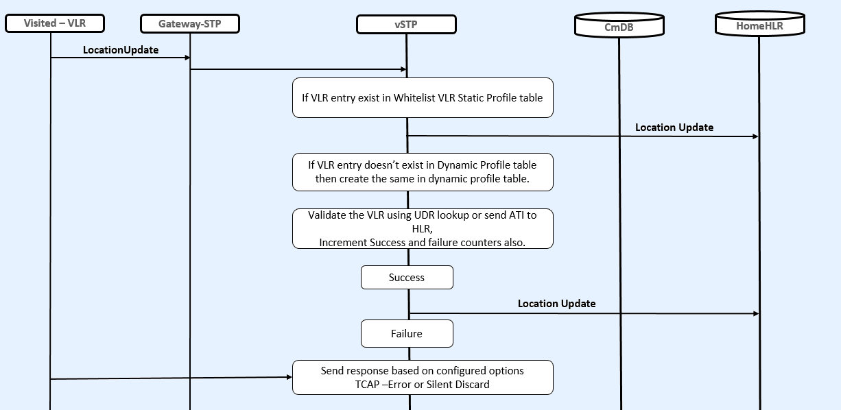
Stateful Security Dynamic Learning
The Stateful Security Dynamic Learning feature enables vSTP to create and use a whitelist that is created as part of learning from the validation attempts defined in VLR Validation. This feature is independent of the category of messages but it provides protection against all the messages coming from VLRs that fail the validation and are not part of the created whitelists. A grey list and black list is also created for the VLRs that fail the validation.
Learning is controlled by these modes using a mode parameter in the SFAPPOPTS table:
-
Learn Mode: This mode allows to learn about new VLRs and no validations are performed. The newly learnt VLRs are considered as whitelisted.
Note:
The user can configure the amount of time for which the vSTP operates in Learn mode. The time is configured in SFAPPOPTS table.Hence, the switch from Learn to Test mode can happen either by configuring the timer, or manual switch.
-
Test Mode: This mode validates all the learned VLRs. In case the VLR is not validated, the learnt VLRs remains greylisted and and measurements and alarms are generated.
-
Active Mode : This mode allows validations based on the learned white lists in the system. New VLRs are also learned in this mode.
The status of dynamically learnt VLRs are changed to whitelist or blacklist as per their status.
- OFF Mode: When none of the above modes is active, it is considered as OFF
mode. In this mode, if VLR entry is in whitelist, then no validation is performed
for that VLR.
By default, the OFF mode remains enabled. That means the SFAPP dynamic learning functinality is disabled.
Note:
- In any mode, if VLR is in whitlist table, then it is considered as whitelisted, and the message is forwarded to HLR.
- If user has changed the mode from Learn/Test/Active mode to OFF mode, then the user has to wait for at least 10 mins before switching the mode again to Active/Learn/Test mode.
Call Flow in Learn Mode
This mode does not validate any VLRs and consider all the VLRs interacting with the network as valid. All the New VLRs that are used during this modes shall be added to the dynamic tables.
- Automatically, upon expiry of the
configured learn mode time limit, if configured.
You can configure the time in number of hours for which the vSTP operates in this mode in SFAPPOPTS table. The recommended time period for Learn mode is 6 to 12 hours.
- By manual switching of mode
VLR Validation in Learning Mode
The following figure shows the vSTP call flow for VLR validation in learning mode:
Figure 2-14 VLR Validation in Learning Mode

- The incoming message will
be decoded.
An Error will be generated in case of decode failure.
- The message information will be stored in the local database.
- Lookup in VLR Whitelist
table (static Profile).
- If entry is found for new VLR, then the validation is skipped.
- If entry is not found in static Whitelist VLR table, then the lookup is performed in Dynamic Profile Table (DPT).
-
- If the entry is not available in DPT, then create it with filter as graylisted, and forward the message to HLR.
- If entry is avilable in DPT and it is GL, then forward the message to HLR.
- Also, Send the Create or Update event to UDR for IMSI record.
Velocity Check in Learning Mode
The following figure shows the vSTP call flow for Velocity check in learning mode:
Figure 2-15 Velocity Check in Learning Mode

- The incoming message will
be decoded:
- An Error will be generated in case of decode failure.
- A Measurement will be pegged for the decode failure with OpCode and CgPA.
- The message information will be stored in the local database.
- If New VLR entry is not there is Dyn VLR Profile table then create it.
- The ATI request will be generated toward the HLR identified in the CdPA of the incoming message.
- In case the HLR sends a failure in the ATI response, a measurement will be pegged to identify HLR error corresponding message from CgPA (VLR).
- For a success response, extract the Age of Location from the ATI Response message and the VMSC address in the HLR.
- In case the New VLR from which the SAI/LU was received matches the old VLR in the ATI response, no action is required.
- In case the VLR addresses does not match and old VLR is not available in Dynamic Profile table, then create the entry.
- Lookup in Dynamic Roaming
table (DRT):
- If entry is not available, then create the DRT entry with threshold value as AgeofLocation value received in ATI ack.
- If DRT is already available for the same combination of old VLR and new VLR, and the value of age of location is different than that in the dynamic VLR roaming entry, age of location value in roaming entry is updated to a minimum of the age of location in dynamic VLR roaming entry and the age of location received in ATI ACK. Also Increment the entry_usage_threshold.
- Send the update location to HLR and also send CreateorUpdate event to UDR.
If user has configured the switch-mode timer then after expiry of that timer (in hrs), mode will switch to test mode.
Call Flow in Test Mode
This mode validates all the learned VLRs at all times. In case the VLR is not validated, it is added to greylist and measurements and alarms are generated. These measurements and alarms allows the operator to validate the whitelists and the overall solution, before they choose to go to the Active mode.
- Automatically, upon expiry of the test mode time limit, if configured
- By manual switching of mode
VLR Validation in Test Mode
The following figure shows the vSTP call flow for VLR validation in test mode:
Figure 2-16 VLR Validation in Test Mode
- The incoming message is decoded. An error is generated in case of decode failure.
- The message information gets stored in the local database.
- Lookup in VLR Whitelist
table (Profile).
If entry is available for new VLR, then skip the validation. Otherwise, continue below steps.
- Lookup in DPT:
- If entry is not available for New VLR, then create the Entry in DPT.
- If entry in DPT exists, then VLR validation is performed with lookup in UDR for that IMSI.
- If record is not found in UDR then send ATI to HLR.
- Update success & failure counts based on validation results.
- If validation is success then send location update to HLR and send CreateorUpdate event to the UDR for latest timestamp.
- If validation is failed
then send response based on configured option:
Fail Action Id is FALLBACK (do not discard messages even if the validation fails in test mode for dynamic VLRs)
- The Greylisted dynamic VLRs remain unchanged. They are not moved to Whitelisted or Blacklisted VLRs. However, the event notification for status change (GL->BL, GL->WL, and so on) is raised, based on the threshold values.
Velocity Check in Test Mode
The following figure shows the vSTP call flow for Velocity check in test mode:
Figure 2-17 Velocity Check in Test Mode

- 1. The incoming message
is decoded.
- An Error will be generated in case of decode failure.
- A Measurement is pegged for the decode failure with OpCode and CgPA.
- The message information is stored in the local database.
- If no new VLR entry is available in Dyn VLR Profile table, then create the VLR entry.
- Perform validation by
sending ReadEvent to UDR for that IMSI record.
- If the record is available in UDR, then extract the lastUpdatedTimestamp and VLR from UDR response.
- If the record is not
available in UDR, then ATI request is generated towards the HLR identified in
the CdPA of the incoming message.
For a success response from HLR, extract the Age of Location from the ATI Response message and the VMSC address in the HLR.
- In case the new VLR from which the SAI/LU was received, matches the old VLR in the UDR/ATI response, no action is performed.
- In case the VLR addresses do not match:
- If old VLR is not available in DPT, then create the entry.
- If old VLR status is Blacklisted, then entry is not created in DPT. The velocity check results in Validation Failure.
Call Flow in Active Mode
This mode enables the following actions:
- Learning of new VLRs. The status of existing VLRs get changed as per success or failure counts.
- Handling the dynamic VLRs
based on their status. The following table describes the dynamic VLRs with
status and respective results:
Status Result Whitelist Validation Success. VLR validation is not performed
Blacklist Validation Failure Graylist VLR validation is not performed Note:- Success and Failure validation count is incremented based on validation result.
- The GrayListed dynamic VLRs status can change to Whitelisted or Blacklisted
Successful Validation Count When the net successful validation count reaches threshold, then VLR status is changed to Whitelisted. Note: success count - failure count >= success threshold
Failure Validation Count When the net failure validation count reaches threshold, then VLR status is changed to Blacklisted. Note: failure count - success count > = failure threshold
VLR Validation in Active Mode
The following figure shows the vSTP call flow for VLR validation in active mode:
Figure 2-18 VLR Validation in Active Mode

- If the VLR is available in DPT or Whitelist Profile Table (WPT) as whitelist, then the validation is successful and LocUpdate is sent to HLR.
- In case the VLR is available in DPT as blacklist, then the message is rejected.
- If DPT entry is GL, then VLR validation is performed.
- If entry does not exists, then create new entry in DPT (as learn mode is also enabled in active mode).
- If entry is GL or entry
doesn't exists in DPT, then perform validation such as lookup in UDR.
- If IMSI record is found in UDR, then extract VLR from UDR response.
- If record is not found in UDR then, send ATI to HLR and extract VLR from ATI ACK.
- If old and new VLRs are same, then validation is success, otherwise the validation is failed.
- Move VLR to BL/WL based on the threshold value, validation result, and raised event.
- On successful validation, send CreateorUpdate event to UDR.
Velocity Check in Active Mode
The following figure shows the vSTP call flow for Velocity check in active mode:
Figure 2-19 Velocity Check in Active Mode

- If old and new VLRs are not same, then perform velocity check.
- If the status of the old VLR Blacklisted, then entry is not created in DPT. The velocity check results in Validation Failure.
- Perform lookup in DRT for old and new VLR combination. If entry exists and learning is complete (velocity_threshold exceeds), then perform velocity check using the entry.
- If no DRT entry is available, then create entry using long/lat table time and perform velocity check using that DRT entry. Update UDR if validation is successful. Also update VLR success or failure count, based upon the validation result.
- If entry is available but learning is not complete, then take time from LONG/LAT table and reset the time also with LonG/Lat table Time and Perform velocity check and VLRs count based upon the result.
- Update UDR if validation is successful.
SFAPP Configurations
This section provides procedures to configure the connection required for SFAPP to access the database.
SFAPP is configured using the vSTP managed objects. The MMI API contains details about the URI, an example, and the parameters available for each managed object.
MMI Managed Objects for SFAPP
MMI information associated with SFAPP is accessed from a DSR NOAM or SOAM from .
Once the MMI API Guide displays, use the application navigation to locate specific vSTP managed object information.
Table 2-8 vSTP SFAPP Managed Objects and Supported Operations
| Managed Object Name | Supported Operations |
|---|---|
| SfappNeighboringCountries | Insert, Delete |
| VstpMateStp | Insert, Update, Delete |
| SfappCountryCodes | No operations supported |
| SfappCountrylongLati | No operations supported |
| SfappCCMCCMap | Insert, Delete |
| VstpSccpApplications | Insert, Update, Delete |
| VstpSccpOptions | Update |
SfappNeighboringCountries - Insert, Delete
Execute the MMI Client command from an active SOAM.
 /vstp/SfappNeighboringCountries/
{
    "data": [
        {
            "mcc": 289,
            "name": "Abkhazia",
            "neighMcc": 250,
            "neighName": "Russia",
            "uniqueIdentifier": "289-250"
        },
…
        {
            "mcc": 648,
            "name": "Zimbabwe",
            "neighMcc": 655,
            "neighName": "South Africa",
            "uniqueIdentifier": "648-655"
        },
        {
            "mcc": 648,
            "name": "Zimbabwe",
            "neighMcc": 645,
            "neighName": "Zambia",
            "uniqueIdentifier": "648-645"
        }
    ],
    "links": {},
    "messages": [],
    "status": true
}
/commonsecurity/neighboringcountries/<uniqueIdentifier> -v DELETENo output returned by URI: https://localhost/mmi/dsr/v3.1/commonsecurity/neighboringcountries/648-645? for 'DELETE' operationVstpMateStp - Insert, Update, Delete
Example:
 /vstp/matestps/
{
   "data": [
       {
           "domain": "Itun",
           "pointCode": "13"
       }
   ],
   "links": {},
   "messages": [],
   "status": true
}
Create a file as follows for insert:
$cat matestp.json
{
    "domain": "Itun",
    "pointCode": "13"
}
/vstp/matestps/ -v POST -r <Absolute Path>/<filename>
 /vstp/matestps/ -v POST -r matestp.json
{
    "data": true,
    "links": {},
    "messages": [],
    "status": true
}
/vstp/matestps/<pointCode> -v DELETEExample output:
 /vstp/matestps/12 -v DELETE
No output returned by URI: https://localhost/mmi/dsr/v3.1/vstp/matestps/12? for 'DELETE' operation
SfappCCMCCMap - Insert, Delete
Execute the MMI Client command from an active SOAM.
 /commonsecurity/mappings/
{
    "data": [
        {
            "cc": 1,
            "mcc": 310,
            "ndc": 1,
            "uniqueIdentifier": "1-1"
        },
…
       {
            "cc": 998,
            "mcc": 434,
            "uniqueIdentifier": "998-0"
        }
    ],
    "links": {},
    "messages": [],
    "status": true
}
Execute the following command to display:
/commonsecurity/mappings/<uniqueIdentifier>Example output:
  /commonsecurity/mappings/"998-0"{
    "data": {
        "cc": 998,
        "mcc": 434,
        "uniqueIdentifier": "998-0"
    },
    "links": {
        "delete": {
            "action": "DELETE",
            "description": "Delete this item.",
            "href": "/mmi/dsr/v3.1/commonsecurity/mappings/998-0",
            "type": "status"
        },
        "update": {
            "action": "PUT",
            "description": "Update this item.",
            "href": "/mmi/dsr/v3.1/commonsecurity/mappings/998-0",
            "type": "status"
        }
    },
    "messages": [],
    "status": true
}
[root@fixsetup-soa1 ~]# cat mapping.json
        {
            "cc": 998,
            "mcc": 434
        }
Create a file as follows for insert:
cat mapping.json
        {
            "cc": 998,
            "mcc": 434
        }
Execute the following command to insert:
/commonsecurity/mappings/ -v POST -r <Absolute Path>/<filename>Example output:
 /commonsecurity/mappings/ -v POST -r mapping.json
{
    "data": true,
    "links": {},
    "messages": [],
    "status": true
}
/commonsecurity/mappings/<uniqueIdentifier> -v DELETE /commonsecurity/mappings/"998-0" -v DELETENo output returned by URI: https://localhost/mmi/dsr/v3.1/vstp/gttactions/actid2006? for 'DELETE' operationVstpSccpApplications - Insert, Update, Delete
Execute the MMI Client command from an active SOAM.
 /vstp/sccpapplications/
{
    "data": [
        {
            "appType": "Sfapp",
            "ssn": 67
        }
    ],
    "links": {},
    "messages": [],
    "status": true
}
Execute the following command to display:
/vstp/sccpapplications/<appType> /vstp/sccpapplications/"Sfapp"
{
"data": {
"appType": "Sfapp",
"ssn": 67
},
"links": {
"delete": {
"action": "DELETE",
"description": "Delete this item.",
"href": "/mmi/dsr/v3.1/vstp/sccpapplications/Sfapp",
"type": "status"
},
"update": {
"action": "PUT",
"description": "Update this item.",
"href": "/mmi/dsr/v3.1/vstp/sccpapplications/Sfapp",
"type": "status"
}
},
"messages": [],
"status": true
}
Example output:
     "data": {
        "cc": 998,
        "mcc": 434,
        "uniqueIdentifier": "998-0"
    },
    "links": {
        "delete": {
            "action": "DELETE",
            "description": "Delete this item.",
            "href": "/mmi/dsr/v3.1/commonsecurity/mappings/998-0",
            "type": "status"
        },
        "update": {
            "action": "PUT",
            "description": "Update this item.",
            "href": "/mmi/dsr/v3.1/commonsecurity/mappings/998-0",
            "type": "status"
        }
    },
    "messages": [],
    "status": true
}
[root@fixsetup-soa1 ~]#
Insert
[root@fixsetup-soa1 ~]# cat mapping.json
        {
            "cc": 998,
            "mcc": 434
        }
Create a file as follows for insert:
 $cat sccpapplication.json
{
    "appType": "Sfapp",
    "ssn": 68
}
Execute the following command to insert:
/vstp/sccpapplications/ -v POST -r <Absolute Path>/<filename>
Example:
 /vstp/sccpapplications/ -v POST -r sccpapplication.json
{
    "data": true,
    "links": {},
    "messages": [],
    "status": true
}
$cat  sccpapplication.json
{
    "appType": "Sfapp",
    "ssn": 69
}
/vstp/sccpapplications/ -v PUT -r <Absolute Path>/<filename> /vstp/sccpapplications/ -v PUT -r sccpapplication.json
{
"data": true,
"links": {},
"messages": [],
"status": true
}
/vstp/sccpapplications/<appType> -v DELETEExample output:
 /vstp/sccpapplications/"Sfapp" -v DELETE
No output returned by URI: https://localhost/mmi/dsr/v3.1/vstp/sccpapplications/Sfapp? for 'DELETE' operation
VstpSCCPOptions- Update
Execute the MMI Client command from an active SOAM.
 /vstp/sccpoptions/
{
    "data": {
        "class1seq": "Disabled",
        "dfltfallback": false,
        "dfltgttmode": "Cd",
        "mtprgtt": "Off",
        "mtprgttfallback": "Mtproute",
        "tgtt0": "None",
        "tgtt1": "None",
        "tgttudtkey": "Mtp",
        "tgttxudtkey": "Mtp",
        "travelVelocity": 700
    },
    "links": {
        "update": {
            "action": "PUT",
            "description": "Update this item.",
            "href": "/mmi/dsr/v3.1/vstp/sccpoptions/",
            "type": "status"
        }
    },
    "messages": [],
    "status": true
}
Note:
The travelVelocity is an existing MO and a new parameter "travel_velocity" has been added as part of SFAPP feature. $cat sccpoption.json
{
"class1seq":"Disabled",
"dfltfallback": false,
"dfltgttmode": "Fcd",
"itun16ScmgEnabled":false,
"tgtt0": "None",
"tgtt1": "None",
"tgttudtkey": "Mtp",
"tgttxudtkey": "Mtp",
"mtprgtt": "Usemtppc",
"mtprgttfallback" "Gttfail",
"travelVelocity": 650
}
Execute the following command to update:
/vstp/sccpoptions/ -v PUT -r <Absolute Path>/<filename>Example output:
 /vstp/sccpoptions/ -v PUT -r sccpoption.json
{
    "data": true,
    "links": {},
    "messages": [],
    "status": true
}
Example output:
 /vstp/sccpoptions/
{
    "data": {
        "class1seq": "Disabled",
        "dfltfallback": false,
        "dfltgttmode": "Fcd",
        "mtprgtt": "Usemtppc",
        "mtprgttfallback": "Gttfail",
        "tgtt0": "None",
        "tgtt1": "None",
        "tgttudtkey": "Mtp",
        "tgttxudtkey": "Mtp",
        "travelVelocity": 650
    },
    "links": {
        "update": {
            "action": "PUT",
            "description": "Update this item.",
            "href": "/mmi/dsr/v3.1/vstp/sccpoptions/",
            "type": "status"
        }
    },
    "messages": [],
    "status": true
}
SfappCountryCodes
There is no MMI support available for SfappCountryCodes, but a user can retrieve the data by executing get command on an active SOAM.
SfappCountrylongLati
There is no MMI support available for SfappCountrylongLati, but a user can retrieve the data using get command on an active SOAM.
MMI Managed Objects for SFAPP Dynamic Learning
Table 2-9 SFAPP Dynamic Learning Managed Objects and Supported Operations
| Managed Object Name | Supported Operations |
|---|---|
| SfappOptions | Display, Update |
| whitelistvlrprofile | Insert, Update, Delete |
| vlrprofiles | Display |
| vlrromings | Display |
SfappOptions - Display, Update
Execute the MMI Client command from an active SOAM to display:
/vstp/sfappoptions
Example Output:
{
    "data": [
        {
            "agingTimer": "None",
            "failureThreshold": "4",
            "learnTimer": "5",
            "sfappMode": "Test",
            "successThreshold": "5",
            "velocityThreshold": "40"
        }
    ],
    "links": {},
    "messages": [],
    "status": true
}
Create a file as follows for insert:
cat <filename.json>
{
   "failureThreshold": "5"
}
/vstp/sfappoptions -v PUT -r /tmp/<filename.json>{
"data": [
{
"agingTimer": "None",
"failureThreshold": "5",
"learnTimer": "5",
"sfappMode": "Test",
"successThreshold": "5",
"velocityThreshold": "40"
}
],
"links": {},
"messages": [],
"status": true
}
Whitelist Vlr Profiles - Insert, Update, Delete
Example:
 /vstp/whitelistvlrprofiles/

"data": [
       {
            "filter": "WhiteList",
            "vlr": 1
       }
Create a file as follows for insert:
Cat <filename>
        {
            "filter": "WhiteList",
            "vlr": 1
        }
/vstp/whitelistvlrprofiles –v POST –r /tmp/<filename> {
"data": true,
"links": {},
"messages": [],
"status": true
} /vstp/whitelistvlrprofiles/16 -v DELETEExample output:
/vstp/whitelistvlrprofiles/12 -v DELETE
VLR Profiles - Display
Execute the MMI Client command from an active SOAM.
/vstp/vlrprofiles
{
"data": [
{
"failureCount": 0,
"filter": "GrayList",
"lastUsedTime": "1969-12-31T19:00:00-05:00",
"successCount": 0,
"vlr": "4114001133"
}
],
"links": {},
"messages": [],
"status": true
}VLR Roaming - Display
Execute the MMI Client command from an active SOAM.
/vstp/vlrroamings
{
"data": [
{
"entryUsageCount": 2,
"lastUsedTime": "1969-12-31T19:00:00-05:00",
"newVlr": 65746892,
"oldVlr": 65746892,
"time": 4085,
"uniqueIdentifier": "65746892-65746892"
}
],
"links": {},
"messages": [],
"status": true
}SFAPP Alarms and Measurements
Alarms and Events
The following table lists the Alarms and Events specific to the SFAPP support for vSTP:
| Alarm/ Event ID | Name |
|---|---|
| 70293 | SFAPP Validation Error |
| 70294 | SFAPP Validation Matching State not found |
| 70295 | SFAPP Validation Encoding Error |
| 70296 | SFAPP Validation Response Timeout Error. |
| 70297 | SFAPP Validation Velocity Chk Failed. |
| 70298 | SFAPP Validation Failed
Note: The parameter ageOfLoc and Threshold with zero can be ignored if not relevant for scenarios where this UIM is observed. |
| 70299 | SFAPP Invalid CC/NDC received |
| 70300 | Updation failed in UDR |
| 70301 | VSTP SFAPP Stack Event Queue Utilization |
| SFAPP Dynamic Learning | |
| 70429 | VstpDynVlrStatusChanged |
| 70430 | VstpDynVeloThreshCrossed |
| 70431 | VstpDynVLRProfAging |
| 70432 | VstpDynVLRRoamAging |
| 70433 | VstpVlrDynLearningOFF |
| 70434 | VstpVlrDynLearningLearntimer |
For more details related to Alarms and Events, refer to Alarms and KPIs Reference document.
Measurements
| Measurement ID | Measurement Name |
|---|---|
| 21702 | VstpSfappMsgSuccess |
| 21703 | VstpSfappMsgFailed |
| 21704 | VstpSfappMsgError1 |
| 21705 | VstpSfappMsgError2 |
| 21706 | VstpRxSfappMsg |
| 21707 | VstpRxSfappMsgDiscard |
| 21708 | VstpSfappInternalError |
| 21709 | VstpSfappCADecodeFail |
| 21710 | VstpSfappCATimeOut |
| 21711 | VstpSfappCAAvgProcessTime |
| 21712 | VstpSfappCAMaxProcessTime |
| 21713 | VstpSfappSubsNotFound |
| 21714 | VstpSfappCATx |
| 21715 | VstpSfappCATxFail |
| 21716 | VstpSfappPduFull |
| 21717 | VstpSfappCAProcesTime |
| 21718 | VstpSFAPPStackQueuePeak |
| 21719 | VstpSFAPPStackQueueAvg |
| 21720 | VstpSFAPPStackQueueFull |
| 21782 | VstpTxSfappMsg |
| 21783 | VstpTxSfappMsgPeak |
| 21784 | VstpTxSfappMsgAvg |
| SFAPP Dynamic Learning | |
| 21937 | VstpDynNewVLR |
| 21938 | VstpDynNewRoamEntry |
| 21939 | VstpDynVLRBL |
| 21940 | VstpDynVLRWL |
| 21941 | VstpDynVLRGL |
| 21942 | VstpDynVelCrossed |
| 21943 | VstpDynVLRProfAging |
| 21944 | VstpDynVLRRoamAging |
For more details related to measurements, refer to Measurement Reference document.
UDR Configuration for SFAPP
- Add details about the vSTP MP on the ComAgent Remote Servers screen as a client by navigating to and clicking Insert on an active OCUDR NOAMP.
- Select the OCUDR server group from the Available Local Server Groups that needs to communicate with vSTP MP.
- From the active
OCUDR GUI, navigate to
and verify connection are
InService. - From the active
OCUDR GUI, navigate to
and verify the
STPDbSvc status is
Normal. - From an active DSR NOAM, navigate to and click Insert.
- Add the UDR NO IP in the ComAgent Remote Server screen as a Server.
- Select the STP MP server group from the Local SG that needs to communicate with UDR.
- Also add the Standby and DR NOs to the Local SG.
- Navigate to , select STPSvcGroup and click Edit.
- Add all available UDR NO servers.
- Navigate to , select the server name, and check the connection status.
Steps to Enable SFAPP Feature on UDR:
- Go to the path:
/usr/TKLC/udr/prod/maint/loaders/upgrade - On the path, execute the enableSecurityApp script.
<?xml version="1.0" encoding="UTF-8"?>
<subscriber>
<field name="IMSI">6912347700</field>
<field name="VPLMN">816308</field>
<field name="MCC">611</field>
<field name="MMER">epc.mnc905.mcc679.org</field>
<field name="MMEH">s6amme-epc.mnc905.org</field>
<field name="HSSR">hss@3gppnetwork.org</field>
<field name="HSSH">hss-epc.mnc905.mcc679.3gppnetwork.org</field>
<field name="lastUN">3G</field>
<field name="VLR">12340000</field>
</subscriber>
Note:
An UPDATE request from vSTP is assigned to an Active UDR only. However, a READ request from vSTP can be assigned to both Active or Standby UDR.To check the status of the UDR, navigate to Communication AgentMaintenanceHA Services Status. Check value for the Active SRs field for the UDR. If the value is 1, the UDR is in active status. Therefore, an UPDATE request will be sent to this UDR.
Troubleshooting
The vSTP SFAPP sends default response in case of the following scenarios:
- SFAPP thread CPU utilization
exceeds congestion level
Check if the SFAPP thread CPU utilization exceeded Congestion Level 2. This check is performed at the beginning of the message processing cycle and if set, vSTP immediately responds with default response.
The equipment status value set against eirDefRespInErr option of EirOptions table is sent right away.
- SFAPP operational state
Check if the SFAPP operational state is Unavailable. vSTP performs this check before sending the message to UDR and if the state Unavailable, the default response is sent and the query is not sent to UDR. The VstpSfappCATimeOut meal is pegged in this scenario.
The following points must be considered while configuring SFAPP over vSTP:
- The J1 and ATM interfaces are not supported.
- Single vSTP MP VM can support only one 4-Port ADAX HDC3 Card.
- An ADAX HDC3 card cannot be accessed from Multiple VSTP MP VMs .
- The ADAX HDC3 driver components and RPMs needs to be installed separately.
- The DSR patch is required to be applied on vSTP MP VM that is connected to ADAX HDC3 card.
- In SFAPP dynamic learning, when no new VLRs get reflected in the replicated tables (VstpSfappVlrProfile/ VstpSfappVlrRoaming), then ensure that the vSTP OAM process is up and running on SOAM and its not under reboot.
Support for CAT2 SS7 Security
The CAT2 SS7 Security functionality allows vSTP to detect anomalies on inbound Category 2 packets through bulk upload of customer IR.21 documents.
Note:
The IR.21 document contains operator wise network information such as, MCC-MNC, Node GT (HLR/VLR/MSC), and CC-NDC.For detailed information about this feature, refer to vSTP SS7 Security User's Guide.
Feature Overview
vSTP provides the IR.21 Utility to read and record the information present in GSMA IR.21 document.
The SCPVAL GTT Action addresses the SS7 CAT2 security checks. This GTT action ensures that the MSU details such as, CGPA and IMSI belongs to same operator after validating it with the newly generated table.
The CAT2 SS7 functionality is described as follows:
Note:
The information can also be populated using MMIs. However, it is not the preferred method.The GTT is configured to enforce CAT 2 validation on the received MSUs. The validation is performed based on the data available in IR21RoutingInfo and IR21NetworkElement tables.
CAT2 SS7 Security Workflow
The following flow chart provides an overview of the CAT2 SS7 Security functionality:
Figure 2-20 CAT2 SS7 Security Workflow

- Conversion of IR21 xml file
- vSTP provides the IR21 Utility on SOAM. The IR21 Utility accepts operator IR21 input file in XML format and generate error message in case of no or other than IR21 XML files.
- The output is generated in the form of two CSV files named
IR21NetworkElement.csvandIR21RoutingInfo.csv. - The enteries in the CSV files have length based validation for all fields. For example, sender TADIG code and TADIG code must be of 5 digits, IMSI must be of 6 digits, Node Type must be of 1 digit, GT Address range must be of 15 digits.
- The
IR21NetworkElementtable stores value 0 for HLR and 1 for MGT. Therefore, no validation is performed on this value.
Note:
The IR21 utility supports parsing of 1000 IR.21.xml input files in alphabetical order in an instance. For more details on IR21 Utility, see GUI Configurations for CAT2 SS7 Security Support. - Bulk upload after conversion
The generated CSV files are imported using the Import option under Diameter Common on SOAM.
The following data is extracted from IR21 file and stored on vSTP:- Sender TADIG code (RAEX IR.21 Information) : It is retrieved from the RAEX IR21 FileHeader tag and used to identify the operator. It consist of two fields, with a total length of five characters consisting of three-character country code and a two character operator or company idenfier. Sender TADIG code is stored against each entry.
- Routing Information Data (Section ID 4) : It is a mandatory
section in IR21 document of the operator. The vSTP
IR21RoutingInfotable stores the MCC-MNC (E.212) along with TADIG code from this section. The vSTPIR21NetworkElementstores the CC-NC (from E.214) along with TADIG code from this section. - Network Element Information Data (Section ID 13) – It is an
optional section in IR21 document of the operator. The vSTP
IR21NetworkElementtable stores the HLR Node type GT address or Address range along with the TADIG code from this section.
- Validation
The SCPVAL GTT action validates that the MSU details: CgPA and IMSI belongs to same operator. The validation is performed using the data available in
IR21RoutingInfoandIR21NetworkElementtables.The following OPCODES are applicable for CgPA and IMSI validation:- provideRoamingNumber (4)
- provideSubscriberInfo (70)
- provideSubscriberLocation (83)
- cancelLocation (3)
- insertSubscriberData (7)
- deleteSubscriberData (8)
- getPassword (18)
- reset (37)
- activateTraceMode (50)
- unstructuredSS-Request (60)
- unstructuredSS-Notify (61)
- informServiceCentre (63)
- alertServiceCentre (64)
- setReportingState (73)
- remoteUserFree (75)
- istCommand (88)
- Mobile Country Code (MCC): Consists of 3 digits
- Mobile Network Code (MNC): Consists of 2 or 3 digits
- Mobile Subscriber Identification Number (MSIN): 9 or 10 digits
The MCC and MNC parameters (first 5-6 digits) determine the Operator ID. Hence, these values are used during CAT2 validation.
At first, the match is performed with 6 digit, and if the match is not found, then it is performed with 5 digits. In case, the match is not found, the validation gets failed.
Feature Configurations
This section provides procedures to perform the CAT2 SS7 Security functionality.
CAT2 SS7 Security is configured using the vSTP managed objects and vSTP GUI. The MMI API contains details about the URI, an example, and the parameters available for each managed object.
MMI Managed Objects for CAT2 SS7 Security Support
MMI information associated with CAT2 SS7 Security support is accessed from a DSR NOAM or SOAM from .
Once the MMI API Guide gets opened, use the application navigation to locate specific vSTP managed object information.
The following table lists the managed objects and operations supported for CAT2 SS7 Security support:
Table 2-10 CAT2 SS7 Security support Managed Objects and Supported Operations
| Managed Object Name | Supported Operations |
|---|---|
| cat2imsi | Insert, Delete |
| cat2gta | Inser, Delete |
| gttactions | Insert, Delete, Update |
cat2imsi - Insert, Delete
$ cat cat2imsi.json
{
"tadigitCode": "TEST",
"stadigitCode": "TEST",
"mccmnc": "12345"
}Execute the following command on Active SOAM to update the data:
/vstp/cat2imsi -v POST -r cat2imsi.json
Sample Output:
{
"data": [
{
"mccmnc": "12345",
"stadigitCode": "TEST",
"tadigitCode": "TEST"
}
],
"links": {},
"messages": [],
"status": true
}
Cat2Gta - Insert, Delete
$cat cat2gta.json
{
"gttStartAddress": "22345678",
"uniqueIdentifier": "23405678-23405678-HLR",
"stadigitCode": "TEST",
"gttEndAddress": "22345678",
"nodeType": "HLR",
"tadigitCode": "TEST"
}Execute the following command on Active SOAM to insert the data:
/vstp/cat2gta -v POST -r cat2gta.json
Sample Output:
{
"data": [
{
"gttEndAddress": "22345678",
"gttStartAddress": "22345678",
"nodeType": "HLR",
"stadigitCode": "TEST",
"tadigitCode": "TEST",
"uniqueIdentifier": "22345678-22345678-HLR"
}
],
"links": {},
"messages": [],
"status": true
}gttactions - Insert
Execute the following command on Active SOAM to display table data:
$ cat gtt_act.json
{
"valType": "IR21ToTcap",
"ndgt": "All",
"actid": "actval1",
"act": "Scpval"
}Execute the following command on Active SOAM to insert the data:
/vstp/gttactions -v POST -r gtt_act.json
Sample Output:
{
"data": [
{
"act": "Scpval",
"actid": "actval1",
"defactid": "fallback",
"ndgt": "All",
"uimreqd": false,
"useicmsg": false,
"valType": "IR21ToTcap"
} ],
"links": {},
"messages": [],
"status": true
}GUI Configurations for CAT2 SS7 Security Support
The CAT2 SS7 Security functionality can be configured from Active System OAM (SOAM).
To convert IR21 File
On the Active System OAM (SOAM), select VSTP IR21 Utility Conversion.
Figure 2-21 IR21 Utility

The IR21 Utility converts the IR21 XML files to CSV files.
Importing CSV Files
The converted IR21NetworkElemet.csv and
IR21RoutingInfo.csv files can be imported from Active System
OAM (SOAM).
The Group Code parameter must be configured in the Local Signalling Points and Remote Signalling Points options. Select VSTP Diameter Common Import. The page lists all the IR21 files under File Management > IR21XMLGUI directory.
Figure 2-22 Importing IR21 CSV Files

For more details on IR21 Utility GUI configurations, see unresolvable-reference.html#GUID-877C2248-9F6F-46EE-A0A4-509B7039BF0E .
CAT2 SS7 Security Alarms and Measurements
Alarms and Events
There are no alarms or events specific to the CAT2 SS7 Security functionality.
Measurements
| Measurement ID | Measurement Name |
|---|---|
| 21971 | VstpGttActScpvalCat2Total |
| 21972 | VstpGttActScpvalCat2Discard |
| 21973 | VstpGttActScpvalCat2NotApplied |
| 21974 | VstpCgpaGttActScpvalCat2Total |
| 21975 | VstpCgpaGttActScpvalCat2Discard |
| 21976 | VstpCgpaGttActScpvalCat2NotApplied |
For more details related to measurements, refer to Measurement Reference document.
Troubleshooting CAT2 SS7 Security
In case of the error scenarios, the measurements specific to CAT2 SS7 Security feature are pegged. For information related to CAT2 SS7 Security measurements, see CAT2 SS7 Security Alarms and Measurements.
vSTP SMS Home Router
The vSTP SMS Home Router feature provides network monitoring for abnormal SMS activities, by obtaining statistics or reports from the SS7 FW. This feature enables vSTP to filter and accept the SMS traffic as per GSMA guidelines.
In order to address spoofing and spamming issues, the SMS Home Router functionality enables all the Managed Objects (MOs) and MT SMs to be routed via an SMS‑SC‑like logical entity (SMS ProxyService) located in the HPLMN of the receiving MS. An SMS signaling FW is provided to analyze MO and MT packets, before submitting or delivering.
Feature Description
With the Home SMS Router feature, a new vSTPService MP or node is introduced in the vSTP architecture. This node analyzes and validates the MO and MT packets before submitting or delivering.
All the configurations related to Home SMS Routing feature are managed using vSTPService. If SMS Service is enabled for a Linkset on SS7 MP, then SS7 MP forwards the SMS message to vSTPService for SMS routing to handle the possible attacks, such as spoofing, spamming, and DOS attacks.
If more than one vSTPService is present in the architecture, then message are forwarded to different vSTPService MPs in round-robin fasion. SS7 MP forwards the message to vSTPService MP via ComAgent Connection. vSTPService MP does not send the message to any external node directly. It is done via SS7 MP.
The following sections describes the possible SMS attacks and the call flows used by vSTP to prevent them.
MO Spoofing
This section explains MO Spoofing. MO Spoofing occurs when a sender manipulates address information.
It is an SMS MO with a manipulated A-MSISDN (real or wrong) coming into the HPLMN network from a foreign VLR (real or wrong SCCP Address). As per HPLMN, it is the roaming scenario where one subscriber is in roaming and sending SMS. However, it is not a real subscriber. The message is not sent by a real mobile but is generated from a specific system with a C7 application. The A-MSISDN being used can be real or not depending on the screening in place in the HPLMN SMS-C (Screening on CC+NDC or No A-MSISDN screening in place.
- SM-RP-DA (Short-Message Relay-Protocol Destination-Address) field
- RP-Destination Address (Relay Protocol-Destination Address) field
- TP-Destination Address (Transfer Protocol-Destination) field
Note:
SPAM messages can be sent from a valid originator. MO Spoofing is not used to block the spam messages. MO Spoofing is handled by processing MO_FSM packets and perform extra validation on vSTPService MP.Handling MO Spoofing
The SMS Home Router functionality provides a new service MP that enables vSTP to perform extra validations address the MO-Spoofing issue.
- Forward MO_FSM (Opcode 46) to ServiceMP
- Extract A party details (MSISDN) and perform SRISM
- CDPA Digits: A MSISDN
- CGPA Digits : ProxyVM
- GTMAP Layer : A MSISDN
- Extract VLR & IMSI from SRISM_ACKMatch VLR ID (from SRISM_ACK) and CGPA of the original MSU
- Match IMSI (SRISM_ACK) and Original MSU
- Match SM-RP-DA and CDPA in original MOFSM MSU (SCCP VAL MOFSM).
After successful validation forward the MSU back to vSTP MP for further routing.
Note:
This action is not performed, if CGPA of the incoming MSUs matches the trusted MSC/VLR list.The vstpSmsProxySMSCStatus MO is used to configure the MSC/VLR list, whether it is allowed or blocked. If it is allowed, then no validation on service message is performed and the message is forwarded back to SS7 for further routing. If the MSC is blocked, then it is considered as validation failure. The default action is applied on the service MP.
The following figure describes the MO-FSM call flow:

MT Spoofing
MT Spoofing involves the manipulation of SCCP or MAP addresses. A fake SMS is originated from the international C7 network and terminated to a mobile network. The originating MS's HPLMN delivers the Short Message directly to the receiving MSs VPLMN after querying the HLR for the current location of the receiving MS. Thus, the HPLMN is not present in the MT routing of the actual data, such as SM.
There is currently no specific correlation between the MAP_SRI_For_SM MAP operation and the subsequent MAP_MT_Forward_Short_Message MAP operation(s). This missing correlation is exploited by hackers to make spam, flooding and faking.
- Fraudulently manipulate MTFSM to send SMS on another operator’s account.
- SMSC of an MTFSM doesn't reflect the actual originating network.
- MAP and SCCP layer both can be spoofed.
- Terminating charges are billed to spoofed network.
- MTFSM spoofing is used for premium rate service.
- Fraudster send SRISM for subscriber and get the serving VLR details.
- Terminates MTFSM directly to subscriber without association of any HPLMN nodes.
MT Spoofing is handled by processing 2 packets (SRISM and MTFSM) on vSTPService MP. In HomeSMSC routing feature, SMSPROXY performs the validation to handle the MT spoofing issues.
Handling MT Spoofing - SRI_SM
The SMS Home Router functionality provides a new service MP that enables vSTP to perform extra validations address the MT-Spoofing issue.
- Forward SRISM (Opcode 45) to vSTPServiceMP
-
Store CGPA (SMSC GT) in a local DB.
-
Modify SRISM CGPA with SMSPROXY GT.
-
- Route the modified SRISM to HLR.
- SRISM_ACK is received at vSTPServiceMP(GT routed).
- Generate scrambled IMSI using random key.
- Store actual IMSI, scrambled IMSI and MSC/VLR GT with the SMSC GT.
- Modify SRISM_ACK and send it to originating node.
- IMSI replaced with scrambled IMSI
- MSC/VLR GT replaced with one of the multiple SMSPROXY GT
- Remove LMSI if present
- CDPA is replaced with SMSC GT
- CGPA is replaced with SMSPROXY GT
Note:
The above action is not be performed, if CGPA of incoming MSUs matches the trusted or blocklisted SMSC list.The following figure describes the MT FSM call flow:
Figure 2-23 MT Spoofing_SRI SM

Handling MT Spoofing - MT_FSM
A brief description of the call flow for MT_FSM packet is available below:-

•SM-RP-DA with scrambled IMSI •SM-RP-OA with fake/real GT of SMSC •RP-OA with fake/real GT of SMSC •TP-OA with fake/real A MSISDN •Forward MT FSM to vSTPService MP(GT routed). •Use scrambled IMSI to correlate with the stored information. •Match SMSC GT from DB with the CGPA & MAP field.
Scrambled IMSI replaced with actual IMSI from DB
SMSPROXY GT replaced with actual VLR/MSC GT from DB.
The following figure describes the MT FSM call flow:
DOS Attack
- MWI flag is enabled in the HLR and MSC after a failed delivery event or failed paging attempt to a specific subscriber. In the HLR, the MWI is set only by the MAP-REPORT-SM-DELIVERY-STATUS message from the SMSC.
- While MWI is set in the HLR, the HLR will NOT respond to any non-priority MAP-SEND-ROUTING-INFO-FOR-SM messages with MAP-INFORM-SERVICE-CENTRE.
- This prevents the SMSC to get routing information for the subscriber and to deliver the SMS using MT_FSM •Abnormal use of the MAP-REPORT-SM-DELIVERY-STATUS Message is used to achieve a MT-SMS Denial of Service (DOS) attack on a specific or a set of customer.
DOS Attack is handled by processing MAP_DELIVERY_STATUS_REPORT on vSTPService MP. Extra validations are performed in order to handle the DOS attack.
Handling DOS Attack
- SMS SFW receives MT_FSM and IMSI is searched in local DB
- If the record is found in the DB, then the MT_FSM record is created in local DB
and forwarded to VLR ID stored in the DB. A timer starts after MT_FSM is
received at DB.
- If the delivery status report is received before the timer expires, it is processed and sent to HLR. The MT_FSM entry is deleted from local DB, once the timer expires.
- If the delivery status report is received after timer is expired (No MT_FSM entry is found in DB), then it is discarded.
- If the record is not found in the DB, then the delivery status report is discarded.
The following figure describes the call flow to prevent DOS attacks:

vSTP Architecture
To address the possible attacks, a service MP is introduced for SMS SFW functionality in vSTP. The SS7 MPs and ServiceMPs remain in same site (SO), but in different server groups. Hence, total MPs per SO is an addition of SS7MPs and Service MPs.
The following figure shows the vSTP architecture with new service MP:
Figure 2-24 vSTP Architecture

In the architecture,
NOAM is the A-Level Server Group.
SOAM is the B-Level Server Group.
SS7 MP & Service MP are the C- level Server Group
There is an automatic ComAgt connection between SS7MPs and Service MPs.
vSTPServiceVMs remain in HA Active/Standby Mode.
vSTPService process runs on all the ServiceVMs, so that traffic gets processed by all the Service VMs
Processing on SS7 MP
The MSUs received at SS7 after the validation at vSTPService MP or after applying default action (fallback) on vSTPService MP, follows the GTT framework to route the packets, such as GTT selector and other GT and MNP related features. Applicable features are SMSNP/FLOBR/TOBR/MBR.
The following figure describes the connection of vSTP with SS7 MPs

- Run the
plcommand on the service MP. - Verify that vstpservice process is not available.
- Start the vstpservice application on service MP.
Run
pm.seton vstpservice. - Execute
plcommand to verify that vstpservice process is running.
Feature Configurations
This section provides procedures to perform the vSTP SMS Home Router Security functionality.
The SMS Home Router is configured using the vSTP managed objects and vSTP GUI. The MMI API contains details about the URI, an example, and the parameters available for each managed object.
MMI Managed Objects for SMS Home Router Support
MMI information associated with SMS Home Router support is accessed from a DSR NOAM or SOAM from .
Once the MMI API Guide gets opened, use the application navigation to locate specific vSTP managed object information.
The following table lists the managed objects and operations supported for SMS Home Router support:
| Managed Object Name | Supported Actions |
|---|---|
| Link Set | Insert, Update, Delete |
| Sccp Application | Insert, Update, Delete |
| Sccp Options | Update |
| Vstp SMS Proxy Options | Update |
| Vstp SMS Proxy SMSC Status | Insert, Update, Delete |
linkset - Insert, Update, Delete
$cat linkset.json
{
"asNotification": true,
"asls8": false,
"cgGtmod": false,
"cgpnblSet": "None",
"configurationLevel": "18",
"enableBroadcastException": true,
"gnameset": "Both",
"gttmode": "Fcd",
"islsrsb": 1,
"ituTransferRestricted": false,
"l2TimerSetName": "Default",
"l3TimerSetName": "Default",
"linksetAccMeasOption": "No",
"localSignalingPointName": "lsp2",
"maximumLinkTransactionsPerSecond": 1000,
"name": "ls2",
"numberSignalingLinkAllowedThreshold": 1,
"numberSignalingLinkProhibitedThreshold": 1,
"randsls": "Off",
"remoteSignalingPointName": "rsp2",
"reservedLinkTransactionsPerSecond": 1000,
"routingContext": 0,
"rsls8": false,
"securityLogging": "Off",
"slsci": false,
"slsrsb": 1,
"smsProxy": "Off",
"type": "M3ua"
}Execute the following command on Active SOAM to insert the data:
/vstp/linksets/ -v POST –r linkset.json
{
    "data": true,
    "links": {},
    "messages": [],
    "status": true
} Sample Output:
{
    "data": [
        {
            "asNotification": true,
            "asls8": false,
            "cgGtmod": false,
            "cgpnblSet": "None",
            "configurationLevel": "18",
            "enableBroadcastException": true,
            "gnameset": "Both",
            "gttmode": "Fcd",
            "islsrsb": 1,
            "ituTransferRestricted": false,
            "l2TimerSetName": "Default",
            "l3TimerSetName": "Default",
            "linksetAccMeasOption": "No",
            "localSignalingPointName": "lsp2",
            "maximumLinkTransactionsPerSecond": 1000,
            "name": "ls2",
            "numberSignalingLinkAllowedThreshold": 1,
            "numberSignalingLinkProhibitedThreshold": 1,
            "randsls": "Off",
            "remoteSignalingPointName": "rsp2",
            "reservedLinkTransactionsPerSecond": 1000,
            "routingContext": 0,
            "rsls8": false,
            "securityLogging": "Off",
            "slsci": false,
            "slsrsb": 1,
            "smsProxy": "On",
            "type": "M3ua"
        }
    ],
    "links": {},
    "messages": [],
    "status": true
}
sccpapplication - Insert, Update, Delete
Attributes
| Parameter | Value | Default | Description |
|---|---|---|---|
| appType | Eir, Atinp, Inpq, Sfapp, SmsProxy | - | Type of Application. |
$cat sccpapplication.json
        {
            "appType": "SmsProxy",
            "ssn": 28
        }
Execute the following command on Active SOAM to insert the data:
/vstp/sccpapplications/ -v POST –r sccpapplication.json
Sample Output:
{
"data": true,
"links": {},
"messages": [],
"status": true
}
sccpoptions – Update, Display
Attributes
| Parameter | Value | Default | Description |
|---|---|---|---|
| smsDelivery | On, Off | Off | SMS Proxy Delivery Functionality Status. |
| smsOrigination | On, Off | Off | SMS Proxy Origin Functionality Status. |
| smsTermination | On, Off | Off | SMS Proxy Terminate Functionality Status. |
$cat sccpoption.json
{
        "allowedFirstSegLen": 0,
        "alwMsgDuringRsmblyErr": false,
        "class1seq": "Disabled",
        "dfltfallback": false,
        "dfltgttmode": "Cd",
        "isSegXUDTfeatureEnable": false,
        "mtprgtt": "Off",
        "mtprgttfallback": "Mtproute",
        "reassemblyTimerDurationAnsi": 5000,
        "reassemblyTimerDurationItu": 10000,
        "segmentedMSULength": 200,
        "smsDelivery": "Off",
        "smsOrigination": "On",
        "smsTermination": "On",
        "tgtt0": "None",
        "tgtt1": "None",
        "tgttudtkey": "Mtp",
		"tgttxudtkey": "Mtp",
        "travelVelocity": 700
    }
Execute the following command on Active SOAM to insert the data:
/vstp/sccpoptions/ -v PUT –r sccpoption.json
Sample Output:
{
"data": true,
"links": {},
"messages": [],
"status": true
}
VstpSmsProxyOptions – Update, Display
Attributes
| Parameter | Value | Default | Description |
|---|---|---|---|
| MofsmDfltActn | Fallback, Discard, Udts, Tcaperr | Discard | Default Action for MOFSM message validation failure. |
| MofsmErrCode | 0-255 | 0 | If Default action is Udts or TcapError, this error code is sent in response. |
| MtfsmDfltActn | Fallback, Discard, Udts, Tcaperr | Discard | Default Action for MT-FSM message validation failure. |
| MtfsmErrCode | 0-255 | 0 | If Default action is Udts or TcapError, this error code is sent in response. |
| MofsmScpval | On, Off | On | Whether to perform SccpVal for MO-FSM message. |
| MtfsmScpval | On, Off | On | Whether to perform SccpVal for MT-FSM message. |
| MtfsmInvkTimer | 30-120 | 60 | MT-FSM Timer. The MT-FSM should be received within this timer once the SRI-SM-Ack is sent to the originator. |
| SmdsDosTimer | 30-120 | 60 | Initiated after MTFSM is forwarded to the VLR. The SMS Delivery Status (if required) should be received before this timer expires. |
| SmsProxyGta |
a-f,A-F,0-9 Min Len : 5 Max Len : 15 |
“” | Global Title Address digits to identify the SMS Proxy Service. |
| SmsProxyTT | 0-255 | 0 | Translation type of CGPA to be used by the SMS Proxy service when generating Messages towards HLR. |
| ScmblImsiPrefix |
a-f,A-F,0-9 Min Len : 5 Max Len : 10 |
“” | Prefix Digits for the Scrambled IMSI. Also defines the range of Scrambled IMSIs to be used. |
| ScmblImsiLen | 14-15 | 15 | Total length of the IMSI to be sent as Scrambled IMSI in SRI-SM Ack. |
| Defcc |
a-f,A-F,0-9, None Max Len : 4 |
- | Default country code. |
$cat smsproxyoptions.json
       {
            "Defcc": "12",
            "MofsmDfltActn": "Udts",
            "MofsmErrCode": 2,
            "MofsmScpval": "On",
            "MtfsmDfltActn": "Tcaperr",
            "MtfsmErrCode": 0,
			"MtfsmInvkTimer": 120,
            "MtfsmScpval": "On",
            "ScmblImsiLen": 15,
            "ScmblImsiPrefix": "1234567",
            "SmdsDosTimer": 60,
            "SmsProxyGta": "12345678",
            "SmsProxyTT": 0
        }
Execute the following command on Active SOAM to insert the data:
/vstp/smsproxyoptions/ -v PUT –r smsproxyoption.json
Sample Output:
{
"data": true,
"links": {},
"messages": [],
"status": true
}
VstpSMSProxySMSCStatus – Insert, Update, Display, Delete
Attributes
| Parameter | Value | Default | Description |
|---|---|---|---|
| smscGttAddr |
a-f, A-F, 0-9 Max Len : 21 |
- | Global Title Address of SMSCs to be allowlisted or blocklisted. |
| smscStatus | AllowList, BlockList | - | Indicates allowlist or blocklist status of SMSC. |
$cat smsproxystatus.json
{
    "smscGttAddr":  "2234567891",
    "smscStatus": "ALLOWLIST"
}
Execute the following command on Active SOAM to insert the data:
/vstp/smscstatus -v POST –r smsproxystatus.json
Sample Output:
{
"data": true,
"links": {},
"messages": [],
"status": true
}
GUI Configurations for Home SMS Router Support
The SMS Home Router functionality can be configured from Active System OAM (SOAM). Select VSTP page.
- SCCP Options
- Linkset
- SCCP Application
- SMS Proxy Options
- SMS Proxy SMSC Status
For more information, see GUI Configuration in Oracle Communications vSTP User's Guide.
Home SMS Router Alarms and Measurements
Alarms and Events
The following table lists the alarms or events specific to the Home SMS Router functionality for vSTP:
| Event ID | Event Name |
|---|---|
| 70447 | smsProxyValidationFailed |
| 70448 | smsProxyValRspTimeout |
| 70449 | smsProxyEcdError |
| 70450 | smsProxyDcdError |
| 70452 | smsProxyAllowlist |
| 70453 | smsProxyBlocklist |
| 70454 | smsProxySccpValidFail |
| 70455 | smsProxyMtfsmInvkTimeout |
| 70456 | smsProxyDosInvkTimeout |
| 70446 | VstpServiceStackEventQueueUtil |
| 70451 | serviceMpUnavailable |
Measurements
| Measurement ID | Measurement Name |
|---|---|
| 22180 | VstpSMSProxyMOSMTx |
| 22181 | VstpSMSProxyMOSMTxFail |
| 22182 | VstpSMSProxyMOSMRx |
| 22183 | VstpSMSProxyMOSMValSuc |
| 22184 | VstpSMSProxyMOSMValFail |
| 22185 | VstpSMSProxyMOSMMsgDiscard |
| 22186 | VstpSMSProxyDecodingFail |
| 22187 | VstpSMSProxyEncodingFail |
| 22188 | VstpSMSProxyInternalError |
| 22189 | VstpSMSProxyPduFull |
| 22190 | VstpSMSProxyMOSMTxPeak |
| 22191 | VstpSMSProxyMOSMTxAvg |
| 22192 | VstpSMSProxyMOSMRxPeak |
| 22193 | VstpSMSProxyMOSMRxAvg |
| 22194 | VstpServiceStackQueuePeak |
| 22195 | VstpServiceStackQueueAvg |
| 22196 | VstpServiceStackQueueFull |
| 22197 | VstpSMSProxyMOSMAllowlist |
| 22198 | VstpSMSProxyMOSMBlocklist |
| 22199 | VstpSMSProxyMOSccpValFail |
| 22200 | VstpSMSProxyMOSccpValSucc |
| 22201 | VstpSMSProxyMOTx |
| 22202 | VstpSMSProxyMORx |
| 22203 | VstpSMSProxyMOValSuc |
| 22204 | VstpSMSProxyMOValFail |
| 22205 | VstpSMSProxyMOAllowlist |
| 22206 | VstpSMSProxyMOBlocklist |
| 22207 | VstpSMSProxyMOSccpValFail |
| 22208 | VstpSMSProxyMOSccpValSucc |
| 22210 | VstpMOSMTxtoServiceMp |
| 22211 | VstpMTSMTxtoServiceMp |
| 22212 | VstpSRISMTxtoServiceMp |
| 22213 | VstpSMSProxyMTSMTx |
| 22214 | VstpSMSProxyMTSMTxFail |
| 22215 | VstpSMSProxyMTSMRx |
| 22216 | VstpSMSProxySRISMTx |
| 22217 | VstpSMSProxySRISMRx |
| 22218 | VstpSMSProxyMTSMMsgDiscard |
| 22219 | VstpSMSProxyMTSMTxPeak |
| 22220 | VstpSMSProxyMTSMTxAvg |
| 22221 | VstpSMSProxyMTSMRxPeak |
| 22222 | VstpSMSProxyMTSMRxAvg |
| 22223 | VstpSMSProxyMTSMInvkTimeout |
| 22224 | VstpSMSProxyMTSMBlocklist |
| 22225 | VstpSMSProxyMTSMValFail |
| 22226 | VstpSMSProxySRISMBlocklist |
| 22227 | VstpSMSProxyMTSMSccpValFail |
| 22228 | VstpSMSProxyMTSMSccpValSucc |
| 22229 | VstpSMSProxyMTTx |
| 22230 | VstpSMSProxyMTRx |
| 22231 | VstpSMSProxySRITx |
| 22232 | VstpSMSProxySRIRx |
| 22233 | VstpSMSProxyMTAllowlist |
| 22234 | VstpSMSProxyMTBlocklist |
| 22235 | VstpSMSProxyMTValFail |
| 22236 | VstpSMSProxySRIBlocklist |
| 22237 | VstpSMSProxyMTSccpValFail |
| 22238 | VstpSMSProxyMTSccpValSucc |
| 22239 | VstpSMSProxyMsgDiscard |
| 22240 | VstpSMSProxySRISMSucc |
| 22241 | VstpSMSProxyMTSMSSucc |
| 22242 | VstpACKTxtoServiceMp |
| 22243 | VstpSMSProxyMOSMMsgFallback |
| 22244 | VstpSMSProxyMTSMMsgFallback |
| 22245 | VstpSMSProxyDRTx |
| 22246 | VstpSMSProxyDRRx |
| 22247 | VstpSMSProxyDELRPSMTx |
| 22248 | VstpSMSProxyDELRPSMRx |
| 22249 | VstpDELREPTxtoServiceMp |
| 22250 | VstpSMSProxyMTNACKTimeout |
| 22251 | VstpSMSProxyDelRepMsgDiscard |
| 22252 | VstpSMSProxyDELRPValFail |
For more details related to measurements, refer to Diameter Signaling Router Measurement Reference document.
Troubleshooting
In case of the error scenarios, the measurements specific to Home SMS Router feature are pegged. For information related to Home SMS Router measurements, see Home SMS Router Alarms and Measurements.