DSR SCEF Architecture
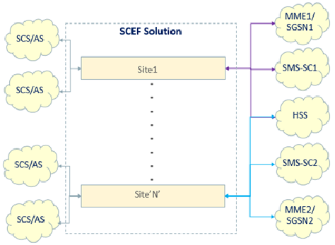
The SCEF solution, supported by a DSR network, contains one or more DSR nodes (sites). Each DSR node may be connected to 3GPP entities, like MME/SGSN, SMS-SC, and HSS, in the trusted domain; and the SCS/AS in the trusted and/or untrusted domain. The connectivity of these nodes with the DSR network is shown in Figure 2-1.
Figure 2-1 DSR-SCEF Interconnections
The DSR architecture is shown in Figure 2-2.
Figure 2-2 DSR SCEF Architecture
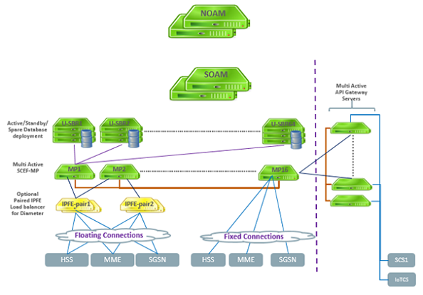
The solution has the following components:
- An API gateway to manage the
REST interface(s) for the following:
- Authentication of SCS/AS
- Support for API lifecycle
- Profile management
- Quota and rate management
- Load balance HTTP traffic among the DA-MP servers
- Network OAM servers deployed in active-standby redundancy model for configuration and maintenance of the DSR topology.
- Site OAM servers deployed in one, two, or three site redundancy model for provisioning of the SCEF administration data.
- IPFE servers (optional) to load balance the Diameter traffic.
- DA-MP server(s) for processing the HTTP (REST) and Diameter signaling according to the provisioning done through the site OAM servers. The DA-MPs receive the HTTP signaling traffic from the SCS/AS using the DSR API gateway application servers and the Diameter signaling traffic from the IPFE servers, if present, or from the connected Diameter peers directly. Diameter traffic generated from DA-MP servers is set to the Diameter peers directly and the HTTP traffic generated from the DA-MP servers shall be routed to the SCS/AS using the DSR API gateway.
- U-SBR server(s) deployed in one, two, or three site redundancy model for caching context data. This data is volatile, that is, the data does not persist with a server reboot, therefore, it is important to plan an adequate redundancy model.
Each SCS/AS may have a configured quota and rate for T8 messages. For example, a quota of 1000 messages in 24 hours at a rate of no more than to 100 messages per hour. Such restrictions are enforced by the DSR API gateway. If the DSR API gateway determines the rate and/or quota to be exhausted, it responds with an appropriate error message to SCS/AS. If the quota and rate are found to be within limits, the DSR API gateway forwards the T8 message to one of the DSR MP servers chosen using a simple round-robin load-sharing algorithm.
For sending a T8 request message to the SCS/AS, the DSR MP servers forward the T8 message to one of the DSR API gateway servers chosen using a simple round-robin load-sharing algorithm.
The DSR MP servers provide the SCS/AS URL in an
X-callback-url header
and provide the callback type as defined in
Table 2-1
in a
X-callback-type header
to the DSR API gateway.
Table 2-1 DSR API Gateway Callback Types
| X-notification-type | Notification Description |
|---|---|
| 1 | Monitoring Event Notification |
| 2 | Device Triggering Delivery Report |
| 3 | NIDD Uplink Data Notification |
| 4 | NIDD Downlink Data Delivery Status Notification |