2 vSTP Features
This chapter provides a high level description of the features associated with vSTP.
2.1 M3UA Protocol
M3UA seamlessly transports SS7 MTP3 user part signaling messages over IP using SCTP. M3UA-connected IP endpoints do not have to conform to standard SS7 topology, because each M3UA association does not require an SS7 link. Each M3UA-connected IP endpoint can be addressed by an SS7 point code unique from the signaling gateway’s point code. vSTP provides M3UA without routing keys.
M3UA does not have a 272-octet Signaling Information Field (SIF) length limit as specified by some SS7 MTP3 variants. Larger information blocks can be accommodated directly by M3UA/SCTP without the need for an upper layer segmentation or re-assembly procedure, as specified by the SCCP and ISUP standards. However, a Signaling Gateway will enforce the maximum 272-octet limit when connected to a SS7 network that does not support the transfer of larger information blocks to the destination.
Note:
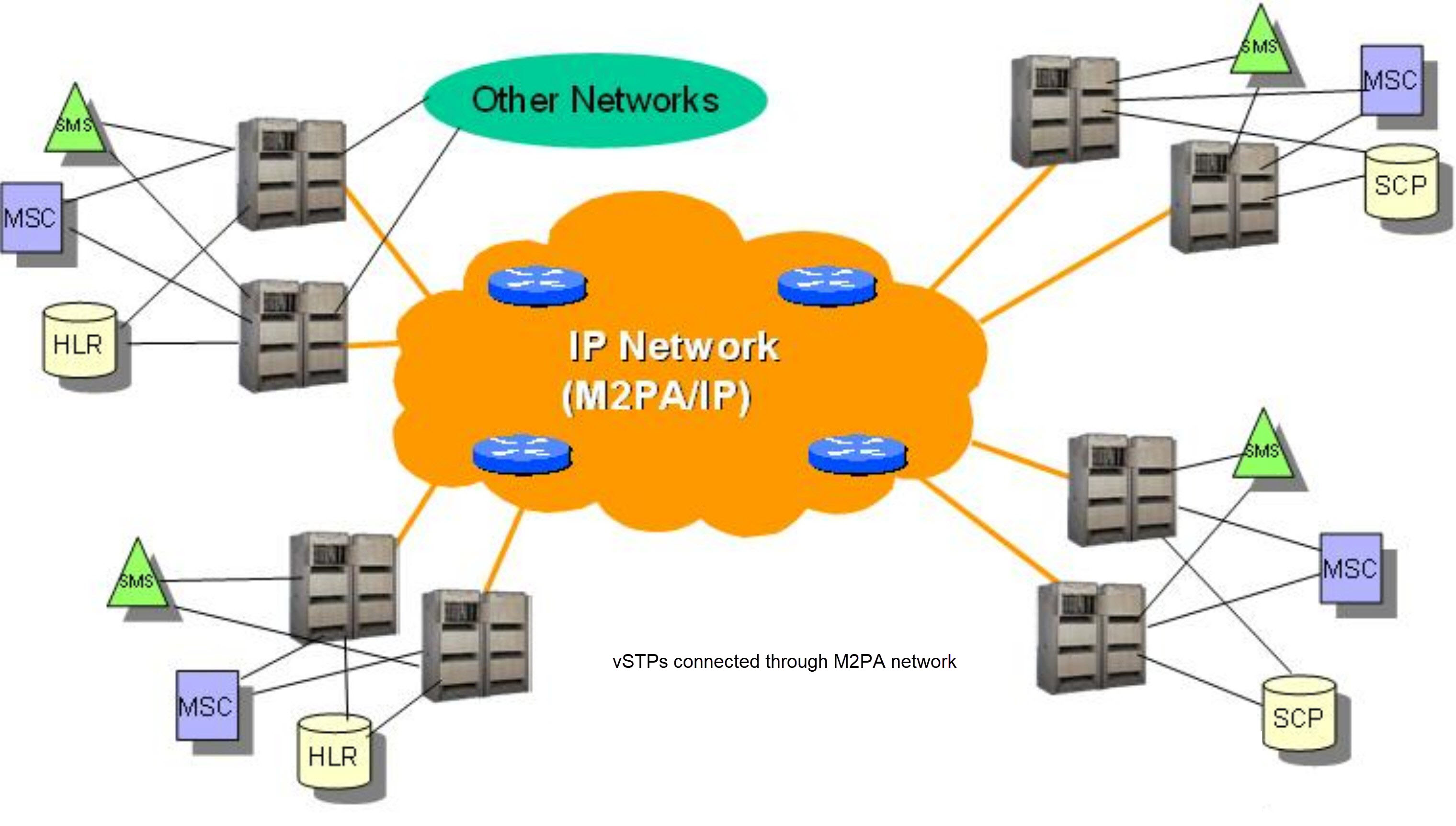
As a Signaling Gateway, vSTP should always be configured as M3UA Server (SG role).2.2 M2PA Protocol
M2PA is used primarily to replace B-, C-, and D-links. When used with A-links, M2PA connects to Service Switching Points, Signaling Control Points, Home Locater Registers and other endpoints. M2PA is a direct replacement for channelized TDM circuits because it provides specific controls for assurance of in-sequence delivery of messages. As such, M2PA is used to connect points that pass call-related data that is time-sensitive, such as ISUP calling data.
Congestion procedures conform to those specified by the ANSI/ITU standards.
Figure 2-1 M2PA Network
2.3 Global Title Translation
The Global Title Translation (GTT) feature is designed for the Signaling Connection Control Part (SCCP) of the SS7 protocol. For detailed information about this feature, refer to vSTP SS7 Security User's Guide.
2.4 Flexible GTT Load Sharing
Flexible GTT Load Sharing (FGTTLS) provides more routing diversity for GTT traffic. There are two parts to Flexible GTT Load Sharing: Flexible Intermediate GTT Load Sharing applied to GTT traffic requiring intermediate global title translation, and Flexible Final GTT Load Sharing applied to traffic requiring final global title translation.
2.4.1 Flexible Intermediate GTT Load Sharing
Flexible Intermediate GTT Load Sharing provides more flexible GTT load sharing arrangements for GTT traffic requiring intermediate global title translation (the routing indicator in the message is GT) than the load sharing arrangements provided by the Intermediate GTT Load Sharing feature. The Flexible GTT load sharing and Intermediate GTT load sharing features are enabled by default to perform Flexible Intermediate GTT Load Sharing.
Intermediate Load Sharing Feature Only
With the Intermediate GTT Load Sharing feature enabled and turned on and the load shares post-GTT destinations when intermediate GTT is being performed through the use of the MRN table. The destination point codes in the MRN table can appear in the MRN table only once. The MRN table contains groups of point codes with a maximum of 32 point codes in each group. This arrangement allows only one set of relationships to be defined between a given point code and any other point codes in the MRN group. All global title addresses in the GTT table that translate to a point code in the given MRN group will have the same set of load sharing rules applied.
For example, the following point codes and relative cost values are provisioned in the MRN table.
   PC             RC
   005-005-005    10
   006-001-001    10
   006-001-002    10
   006-001-003    10
   006-001-004    10
   006-001-005    10
   006-001-006    10
   006-001-007    10
When the point code in the intermediate GTT is translated to 005-005-005, all traffic routed using the global title addresses in the global title translations containing this point code are load shared equally, no matter what the global title address is.
Note:
If you want to provision an IGT or GTT action without load sharing mode, then MRNSET is not specified.2.4.2 Flexible Final GTT Load Sharing
Flexible Final GTT Load Sharing provides more routing diversity for GTT traffic requiring final global title translation (the routing indicator in the message is SSN) than the load sharing arrangements provided by the mated applications without the Flexible GTT Load Sharing feature enabled.
Final Load Sharing Feature Only
The destination point codes and subsystems in the MAP table can appear in the MAP table only once. The MAP table contains groups of point codes with a maximum of 32 point codes and subsystems in each group. This arrangement allows only one set of relationships to be defined between a given point code and subsystem and any other point codes and subsystems in the MAP group. All global title addresses in the GTT table that translate to a point code and subsystem in the given MAP group will have the same set of load sharing rules applied.
When the point code and subsystem in the final global title translation is translated to 005-005-005, subsystem 251, all traffic routed using the global title addresses in the final global title translations containing this point code and subsystem are load shared equally, no matter what the global title address is.
2.5 Weighted GTT Load Sharing
The default behavior for performing load sharing between nodes with the same relative cost is to perform the load sharing in a round-robin fashion. A limitation of this design is that all destinations have equal processing power and should receive an equal load. However, as new hardware is added to load-sharing groups, the load-sharing groups may have different processing capabilities. Customization of the load-sharing group would allow the traffic load to be distributed on the individual characteristics of each destination.
Another default behavior is to route traffic to a load-shared group if any member of that group with the relative cost value is available. Depending on the traffic, this can overwhelm and congest a node, even though other nodes at different relative cost values could have handled the traffic.
Both of these scenarios can be solved with the Weighted GTT Load Sharing feature, which allows unequal traffic loads to be provisioned in mated application (MAP) and mated relay node (MRN) load sharing groups.
The Weighted GTT Load Sharing feature is enabled by default. The MAP and MRN sets are used by MAP and MRN load sharing groups. Weighted GTT Load Sharing can be applied to load shared only or combined dominant/load shared MAP or MRN groups, and cannot be applied to solitary mated applications, or dominant MAP or MRN groups.
This feature also allows provisioning control over load sharing groups so that if insufficient capacity within the load sharing group is available, the load sharing group is not used.
Weighted GTT Load Sharing provides two controls for GTT traffic distribution through either the MAP or MRN groups:
- Individual weighting for each entity in a relative cost (RC) group
- In-Service threshold for each RC group
An RC group is a group of entries in either a MAP group or an MRN group that have the same relative cost value. An entity is either a point code entry in the MRN table or a point code and subsystem number entry in the MAP table.
A MAP group or MRN group can also be referred to as an entity set.
Weighted GTT Load Sharing can be applied to only load shared or combined dominant/load shared MAP or MRN groups, and cannot be applied to solitary mated applications, or dominant MAP or MRN groups.
Individual Weighting
Individual weighting is a method for assigning a different load capacity to each member of an RC group. Each entity is assigned a weight from 1 to 99 and receives a percentage of the traffic equal to its weight relative to the RC group’s total weight. To calculate the percentage of traffic that a particular entity receives within its RC group (assuming all nodes are active and available for traffic), use the following equation:
% of traffic for the entity = (weight value assigned to the entity/RC group weight) x 100%
Note:
With round-robin load-sharing, there is a concept of the preferred entity. The preferred entity is the outcome of GTT. It is the first entity used for load-sharing after initialization, and is the primary entity for Class 1 SCCP Sequenced traffic. When weights are applied, no entity has any preference over another based on GTT information. Distribution is based on the RC group chosen by GTT, not the specific entity.Individual Weighting Example
Table 2-1 shows how weighting affects traffic delivery. Entity A has a weight of 40 and the total RC group weight is 110, entity A receives 36% of the traffic. Entity C is has a weight of 10 and receives only 9% of the traffic for this group. The total group weight is the sum of the individual weight values assigned to each entity in the group.
Note:
In order to maintain 100% for the RC group, some rounding may occur. This rounding error will always be ± 1%.Table 2-1 RC Group Weight Example
| Entity | RC | Weight | RC Group Weight | Percentage of Traffic |
|---|---|---|---|---|
| A | 10 | 40 | 110 | (40 / 110) * 100% = 36% |
| B | 10 | 30 | (30 / 110) * 100% = 27% | |
| C | 10 | 10 | (10 / 110) * 100% = 9% | |
| D | 10 | 30 | (30 / 110) * 100% = 28% |
If all entities in an RC group have the same weight, the outbound traffic pattern provides equal distribution. For weighted load shared or weighted combined load shared MRN or MAP groups with In-Sequence Class 1 SCCP option on, In-Sequence Class 1 SCCP traffic is routed using the provisioned data as the initial method of routing and dynamic data (if the entity selected by provisioned data is prohibited) as the secondary method of routing. This allows all Class 1 traffic to be delivered to the same destination, and the traffic routing is affected unless the original destination changes status. If Transaction-Based GTT Load Sharing is not turned on, then the Weighted GTT Load Shared MSU Key is used. This provides a consistent MSU Key for the Class 1 SCCP
An MSU Key is a value calculated from parameters of an MSU that allows the MSU to be assigned to an entity within an RC group. An MSU Key always maps to the same entity until there is a status change to the MAP or MRN group.
In-Service Threshold
The in-service threshold defines the minimum percentage of weight that must be available for an RC group to be considered available. If the percentage of the available weight is less than the in-service threshold, then the entire RC group is considered unavailable for traffic. If the percentage of the available weight is equal to or greater than the in-service threshold, then the RC group is considered available, and traffic can be sent to any available entity in the RC group. The in-service threshold helps to prevent congestion when only a small portion of the RC group is available.
The in-service threshold has an initial value of 1%, and has a range of values from 1% to 100%. Current round-robin load sharing has an in-service threshold value of 1%, where if any entity in an RC group is available, it is always used.
The group weight that must be available to carry traffic (the required group weight) is determined by multiplying the total group weight (the sum of the individual weight values assigned to each entity in the group) by the in-service threshold value, expressed as a percentage. For example, if the RC group weight is 110, and the in-service threshold is 75%, the required group weight is 82.
An RC group can be in one of three states: Available, Prohibited, and Threshold-Prohibited. These states are determined by comparing the required RC group weight to the weight of the entities that are actually available for traffic, the entity available weight.
If the state of the entity in the RC group is Available, the entity available weight is the weight value assigned to the entity. If the state of the entity in the RC group is either Congested or Prohibited, the entity available weight is 0. The sum of all entity available weights in the RC group is the RC group available weight. Table 2-2 shows how the states of the RC group are determined.
Table 2-2 RC Group In-Service Threshold States
| RC Group State | Description |
|---|---|
| Available | The RC group available weight is greater than or equal to the Required RC group weight. Traffic can routed to the RC group in all circumstances. |
| Prohibited | All entities in the RC group are prohibited (the RC group Available Weight = 0). No traffic can be routed to this RC group. |
| Threshold-Prohibited |
At least one entity in the RC group is not prohibited, but RC group available weight is less than the required RC group weight. Even if the RC group available weight is 0, if one entity is congested, then the state of the RC group is Threshold-Prohibited. Normally, no traffic is routed to this RC group. The Transaction-based GTT Load Sharingand the SCCP Class 1 Sequencing features may route traffic to this group if the primary node is congested. Instead of moving this transaction-based traffic to another node and then back quickly when the congestion abates, routing will continue to the primary node. |
In-Service Threshold Example
In the example shown in Table 2-3, the RC group consisting of entities A, B, C, and D does not have sufficient available weight for the group (70 is less than 82), and therefore the RC group is considered Threshold-Prohibited. This RC group is unavailable for traffic.
The RC group consisting of entities E and F does have sufficient available weight for the group, and the RC group is considered Available.
The RC group consisting of entities G and H is Prohibited, since both entities G and H are Prohibited.
The RC group consisting of entities I and J is Threshold-Prohibited, since entity I is Congested. In order for the RC group status to be Prohibited, all entities in the RC group must be Prohibited. Non-Transaction-Based GTT Load Sharing traffic is not routed to the RC group.
If the Transaction-Based GTT Load Sharing feature is enabled and turned on, or SCCP Class 1 Sequencing is used, then traffic can be routed to entity I if that is the primary entity for the traffic (traffic would be routed if entity I were Available).
Table 2-3 In-Service Threshold Example
| Entity | RC | Wgt. | RC Group Wgt. | In-Service Threshold | Req. RC Group Wgt. | Entity Status | Entity Avail. Wgt. | RC Group Avail. Wgt. | RC Group In-Service Threshold Status |
|---|---|---|---|---|---|---|---|---|---|
| A | 10 | 40 | 110 | 75% | 82 | Available | 40 | 70 | Threshold - Prohibited |
| B | 10 | 30 | Prohibited | 0 | |||||
| C | 10 | 10 | Prohibited | 0 | |||||
| D | 10 | 30 | Available | 30 | |||||
| E | 20 | 30 | 40 | 100% | 40 | Available | 30 | 40 | Available |
| F | 20 | 10 | Available | 10 | |||||
| G | 30 | 20 | 70 | 50% | 35 | Prohibited | 0 | 0 | Prohibited |
| H | 30 | 50 | Prohibited | 0 | |||||
| I | 40 | 25 | 50 | 50% | 25 | Congested | 0 | 0 | Threshold - Prohibited |
| J | 40 | 25 | Prohibited | 0 |
Load-Sharing Groups
Weighted GTT Load-Sharing can be applied to only load shared mated application or MRN groups, or combined dominant/load shared mated application or MRN groups.
A load shared MAP or MRN group is a MAP or MRN group containing entries whose RC (relative cost) values are equal.
When Weighted GTT Load Sharing is applied to load shared MAP or MRN groups, traffic is distributed among the entities according to:
- Entity Status – traffic is only routed to an entity if the entity is considered Available.
- Entity Available Weight – the entity receives a percentage of the traffic determined by its weight relative to the total available weight of the RC group.
- RC group status - refer to Table 2-2.
- Available RC group weight – The sum of all entity available weights in the RC group.
Table 2-4 shows an example of Weighted GTT Load Sharing applied to a load shared MAP or MRN group.
Table 2-4 Load Shared Group with Weighted GTT Load Sharing Example
| Entity | RC | Weight | RC Group Weight | In-Service Threshold | Required RC Group Weight | Entity Status |
|---|---|---|---|---|---|---|
| A | 10 | 40 | 110 | 50% | 55 | Available |
| B | 10 | 30 | Prohibited | |||
| C | 10 | 10 | Available | |||
| D | 10 | 30 | Available |
| Entity | Entity Available Weight | RC Group Available Weight | RC Group In-Service Threshold Status | MAP or MRN Group Status | Current Load % |
|---|---|---|---|---|---|
| A | 40 | 80 | Available | Available | 50% |
| B | 0 | 0 | |||
| C | 10 | 13% | |||
| D | 30 | 37% |
All entities in the load shared group are in the same RC group, so if the RC group is unavailable for traffic, all traffic is discarded.
A combined dominant/load shared MAP or MRN group is a MAP or MRN group containing a minimum of two entries whose RC (relative cost) values are equal and a minimum of one entry whose RC value is different.
When Weighted GTT Load Sharing is applied to combined dominant/load shared MAP or MRN groups, traffic is distributed among the entities according to:
- Entity Status – traffic is only routed to an entity if the entity is considered Available.
- Entity Available Weight – the entity receives a percentage of the traffic determined by its weight relative to the total available weight of the RC group.
- RC group status – refer to Table 2-2.
- Available RC group weight – The sum of all entity available weights in the RC group.
- MRN or MAP Group Status – the MRN or MAP group must be considered Available in order to route traffic.
Table 2-5 shows an example of a weighted combined load shared group.
Based on the results of global title translation, traffic is routed to one of the RC groups in the weighted combined load shared group. If that RC group is unavailable for traffic, the RC group with the next highest cost that is available for traffic is used to route the traffic. If a higher cost RC group is being used to route traffic, and a lower cost RC group becomes available, the lower cost RC group is then used to route the traffic.
The status of the combined dominant/load shared group is based on the status of the RC groups that make up the combined dominant/load shared group. If the status of any RC group is Available, then the status of the combined dominant/load shared group is Available. If no RC group is available for traffic, but the status of at least one of the RC groups is Threshold-Prohibited, then the status of the combined dominant/load shared group is Threshold-Prohibited. If the status of all the RC groups is Prohibited, then the status of the combined dominant/load shared group is prohibited.
Table 2-5 Combined Dominant/Load Shared Group with Weighted GTT Load Sharing Example
| Entity | RC | Weight | RC Group Weight | In-Service Threshold | Required RC Group Weight | Entity Status |
|---|---|---|---|---|---|---|
| A | 10 | 40 | 110 | 75% | 82 | Available |
| B | 10 | 30 | Prohibited | |||
| C | 10 | 10 | Prohibited | |||
| D | 10 | 30 | Available | |||
| E | 20 | 30 | 40 | 100% | 40 | Available |
| F | 20 | 10 | Available | |||
| G | 30 | 10 | 10 | 1% | 1 | Available |
| Entity | Entity Available Weight | RC group Available Weight | RC group In-Service Threshold Status | MRN or MAP Group Status | Current Load % |
|---|---|---|---|---|---|
| A | 40 | 70 | Threshold - Prohibited | Available | 0 |
| B | 0 | 0 | |||
| C | 0 | 0 | |||
| D | 30 | 0 | |||
| E | 30 | 40 | Available | 75% | |
| F | 10 | 25% | |||
| G | 10 | 10 | Available | 100% | |
|
Note: The Current Load % column shows the percentage of traffic each entity in the RC group handles. |
|||||
MSU Routing under Congestion
For Transaction-Based GTT Load Sharing or SCCP Class 1 Sequenced traffic, the original destination of the traffic must be maintained under congestion. Diverting traffic during congestion can lead to invalid transaction states, and the originator is not informed of any problem. If a congested node is selected, then traffic is routed to that node. If the message is discarded, then a UDTS is generated so the originator is informed of a problem. If the node is prohibited, then the selection of an alternate node is acceptable.
For all other traffic, rerouting this traffic away from a congested node is acceptable, since no sequencing or state information needs to be maintained. This can be accomplished by considering a congested entity as Unavailable (thus, its available weight is 0). The congested node receives no traffic. The state of the RC group may transition from Available to Threshold-Prohibited.
2.6 Transaction-Based GTT Load Sharing
Transaction-Based GTT Load Sharing allows messages with the same transaction parameters (TCAP, SCCP, MTP, or ENHMTP parameters) to be routed to the same destination within an entity set.
Caution:
This feature is not enabled by default and once it is enabled, it cannot be disabled. To enable it, use MMI, which is described in the MMI API guide under the Vstp: Feature Admin States section.
An entity set is a group of entities that are used to determine the proper destination of a post-GTT message. This group of entities can be one of the following:
- A mated application (MAP) group
- A mated relay node (MRN) group
- A mated application set (MAPSET), if the Flexible GTTLoad Sharing feature is enabled
- A mated relay node set (MRNSET), if the Flexible GTT Load Sharing feature is enabled.
This feature applies to the following types of SCCP messages:
- UDT/UDTS class 0 messages
- UDT/UDTS class 1 messages
- XUDT/XUDTS class 0 messages
- XUDT/XUDTS class 1 messages.
- MTP parameters - the first 3 bytes of the incoming OPC and 1 byte of the SLS.
- SCCP parameters - the last 4 bytes of the global title address field of the called party address.
- TCAP parameter - the TCAP Transaction ID in the messages.
- Enhanced MTP parameter - a combination of the SLS and the incoming OPC values.
SCCP opts can be changed using MMI. Refer to MMI API documentation for updating the SCCP opts parameter. These parameters are:
tgtt0– enable or disable Transaction-Based GTT Load Sharing for SCCP Class 0 UDT, UDTS, XUDT, or XUDTS messages.tgtt1– enable or disable Transaction-Based GTT Load Sharing for SCCP Class 1 UDT, UDTS, XUDT, or XUDTS messages.tgttudtkey– the Transaction Parameter for the incoming UDT or UDTS messages.tgttxudtkey– the Transaction Parameter for the incoming XUDT or XUDTS messages.
Figure 2-2 describes how the Transaction-Based GTT Load Sharing SCCP options are used.
Figure 2-2 Transaction-Based GTT Load Sharing SCCP Options
Only load shared and combined dominant/load shared entity sets are used to determine the routing for messages that are processed by the Transaction-Based GTT Load Sharing feature.
Using a load shared entity set, the entire entity set is a part of one RC group and the messages are load-shared based on the Transaction Parameter in the entities in the entity set. If none of the entities in the entity set are available for routing, then the message is discarded and a UDTS/XUDTS message is generated if Return on Error is set in the SCCP message. A UIM is generated indicating that the message has been discarded.
Using a combined dominant/load shared entity set, the RC group containing the point code, or point code and SSN, obtained as a result of the global title translation process is used to determine how the message is routed. If none of the entities in this RC group are available for routing, the next higher cost RC group is chosen. This is repeated until an entity in an entity set is available for routing. When an entity is found that is available for routing, the message is routed according to the criteria in that entity. If none of the entities in the entity set are available for routing, the message is discarded. A UDTS/XUDTS message is generated if “Return on Error” is set in the SCCP message. A UIM is generated indicating that the message has been discarded.
2.7 Stateful Application Feature
SS7 Firewall - Stateful Applications (SFAPP) allows vSTP to validate the messages coming in for a subscriber by validating them against the Visitor Location Register (VLR). The last seen details of the subscriber can be fetched from the Home Location Register (HLR). Once the HLR provides a validity of the new VLR, vSTP then allows the message into the network. If the message is not validated, it is handled as per configuration (either silent discard, fallback, or respond with error).
For detailed information about this feature, refer to vSTP SS7 Security User's Guide.
2.8 M3UA Client Support
Note:
- vSTP does not support full M3UA Client (ASP) functionality. M3UA Client configuration can only be used in specific scenarios for STP to STP links.
- vSTP as M3UA client does not support initiation of ASP_DOWN or any other ASPSM and ASPTM messages which are not mentioned in Message Flow for ASP - M3UA Client figure.
- vSTP as M3UA client does not support re-initiation of M3UA association by sending ASPUP on receiving ASP_DOWN_ACK from remote SG, though it updates the internal state to DOWN.
- As per specifications , DUNA(Destination Unavailable)/DAVA (Destination Available)/SCON (Signaling Congested) messages are initiated by SG in ASP-SG communication, but vSTP as M3UA client(ASP) still sends DUNA/DAVA/SCON messages to remote SG.
- vSTP as M3UA client should not be used as End points.
The MTP3-User Adaptation (M3UA ) Client support allows vSTP to trigger the M3UA connection initiation. For information related to M3UA Protocol, refer to RFC 4666.
The M3UA client support over vSTP enables a user to achieve the following functionalities:
-
Initiation of SCTP connection to send INIT message to the server.
-
Initiation of ASP state maintenance messages such as, ASP-UP, ASP-Active etc.
-
Receiving and processing of SS7 Signaling Network Management messages such as, DAVA, DUNA, DUPU, DRST, DAUD and SCON.
-
Receiving and processing of M3UA notify messages (NTFY).
-
M3UA peer receiving the DATA message sends an MTP-TRANSFER indication primitive to the upper layer.
-
On receiving an MTP-TRANSFER request primitive from an upper layer at an ASP the M3UA layer sends a corresponding DATA message to its M3UA peer.
-
The M3UA message distribution function determines the Application Server (AS) by comparing the information in the MTP-TRANSFER request primitive with a provisioned Routing Key.
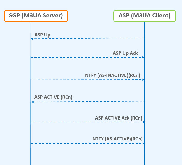
Message Flow
The following figure shows the message flow for M3UA client server functionality, where, SGP acts as the M3UA server and ASP is the M3UA client:
Figure 2-3 Message Flow for ASP - M3UA Client
2.8.1 M3UA Client Support Feature Configuration
This section provides procedures to configure the connection required for M3UA client support.
M3UA client support is configured using the vSTP managed objects. The MMI API contains details about the URI, an example, and the parameters available for each managed object.
2.8.1.1 MMI Managed Objects for M3UA Client Support
MMI information associated with M3UA Client Support is accessed from a DSR NOAM or SOAM from .
Once the MMI API Guide displays, use the application navigation to locate specific vSTP managed object information.
The following table lists the managed objects and operations supported for vSTP M3UA Client Support feature:
Table 2-6 vSTP M3UA Client Support Managed Objects and Supported Operations
| Managed Object Name | Supported Operations |
|---|---|
| connections | Insert, Update, Delete |
| linksets | Insert, Update, Delete |
connections - Insert, Update, Delete
Create a file with following content. File name could be anything, for example option name can be used as filename:
$cat conn.json
{
    "configurationLevel": "0",
    "name": "conn1",
				"connectionMode": "Client",
    "connCfgSetName": "Default",
				"connectionType": "M3UA",
    "localHostName": "lhost1",
				"remoteHostName": "rhost1"
}
linksets - Insert, Update, Delete
cat ls_sample.json
{
					"localSignalingPointName": "lsp111",
 				"numberSignalingLinkProhibitedThreshold": "1",
 				"routingContext": 8, "asNotification": "true",
 				"remoteSignalingPointName": "psps111",
 				"numberSignalingLinkAllowedThreshold": "1",
 				"gttmode": "Fcd", "configurationLevel": "0",
 				"name": "ls1", "ituTransferRestricted": "false",
 				"linkTransactionsPerSecond": "5000",
 				"enableBroadcastException": "true",
 				"cgGtmod": false, "type": "M3ua“
}
The POST operation using REST Call will configure the connection in the client mode.
2.8.1.2 MNP Alarms and Measurements
Alarms and Events
The following table lists the Alarms and Events specific to the M3UA Client Support feature:
| Alarm/ Event ID | Name |
|---|---|
| 19231 | Received Invalid M3UA Message |
| 19235 | Received M3UA Error |
| 19256 | M3UA Stack Event Queue Utilization |
For more details related to alarms and events, refer to Alarms and KPI Guidelines.
Measurements
| Measurement ID | Measurement Name |
|---|---|
| 21271 | VstpTxM3uaDataMsg |
| 21001 | VstpRxM3uaDataMsg |
| 21002 | VstpTxM3uaDataOctets |
| 21003 | VstpRxM3uaDataOctets |
| 21098 | vSTPTxAsnOctets |
| 21099 | vSTPRxAsnOctets |
| 21031 | VstpTxASPUp |
| 21032 | VstpTxASPDown |
| 21033 | VstpTxHeartbeat |
| 21034 | VstpTxASPActive |
| 21035 | VstpTxASPInactive |
| 21036 | VstpRxDUNA |
| 21037 | VstpRxDAVA |
| 21038 | VstpRxDUPU |
| 21039 | VstpRxDRST |
| 21040 | VstpTxDAUD |
| 21041 | VstpRxASPUpAck |
| 21042 | VstpRxASPDownAck |
| 21043 | VstpRxASPActiveAck |
| 21044 | VstpRxASPInactiveAck |
| 21045 | VstpRxM3uaNotify |
For more details related to measurements, refer to Measurement Reference Guide.
2.8.2 Troubleshooting
In case of the error scenarios, the measurements specific to M3UA client support feature are pegged. For information related to M3UA measurements, see M3UA Client Support Alarms and Measurements.
2.9 Time Division Multiplexing
vSTP supports the Time Division Multiplexing (TDM) feature. This feature provides access to E1/T1 links based PCIe TDM Card using PCIe Pass-through.
2.9.1 Feature Overview
The TDM support functionality includes the following components
-
TDM Hardware: The hardware involves PCIe card with physical TDM connectivity supporting Virtual IO. This card contains built-in processor to process the MTP2 layer on hardware itself.
-
MTP Network Interworking Function (NIF): §An additional (MTP Network Interworking Function - NIF) layer will be added to existing VSTP MP so that the MTP3 Layer can communicate with the MTP2 layer running on the TDM PCIe Card.
-
MTP2 Adapter: §The MTP2 Adapter (NIF) layer on VSTP MP shall communicate with MTP2 layer using Virtual-IO calls.
-
Host machine: §The Host machine shall allow PCI Pass-through Access to the vSTP MP virtual machines.
2.9.2 Supported TDM Links
The TDM link implementation supports the following modes:
-
E1 Low Speed Link (LSL) - 64 kbps and 56 kbps
-
T1 Low Speed Link (LSL) - 64 kbps and 56 kbps
-
E1 High Speed Link (HSL) - 2.048 mbps, 12-bit sequence numbers
-
T1 High Speed Link (HSL) - 1.536 mbps , 12-bit sequence numbers
The TDM card supports either E1 or T1 mode at a time. The mode must be defined during driver configuration. It also supports, either HSL or LSL configuration at a time, and it needs to be defined during configuration.
Note:
In case of ADAX card, the MTP2 Adapter layer uses the libraries and APIs provided by ADAX to communicate with ADAX HDC3 Card.
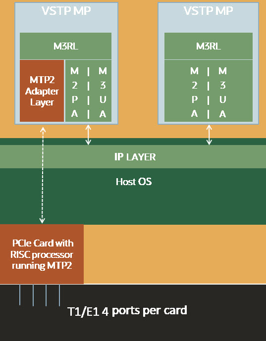
2.9.3 vSTP TDM Support Components
3-Tier vSTP setup installed on the virtualization environment running on underlying Host Servers.
PCIe Card installed on Host Sever(s).
VSTP MP(s) supporting TDM are co-located with TDM card(s) on same host.
MTP2 Adapter layer on VSTP MP communicates with MTP2 Layer running on the PCIe Card.
M3RL Layer and MTP2 Adapter layer exchange data and link primitives.
The following figure describes the component level diagram for the vSTP TDM setup:
Figure 2-4 vSTP TDM Support Components
2.9.4 TDM Protocol Layers
The vSTP TDM support comprises of the following protocol layers:
- MTP2 Adapter Layer (NIF) - Ingress & Egress
- M3RL Layer
- TDM Interface Mapping
The following sections describe these protocols.
2.9.4.1 TDM Interface Mapping
TDM interface is a logical name given to a specific timeslot within a trunk on a TDM PCIe card. The VSTP MP Host Name, Port and time-slot uniquely identifies a TDM Interface. The TDM Link Type (E1/T1) and Speed is specified for each TDM link interface.
Following are possible TDM configuration options:
Table 2-7 TDM Interface Mapping (eLynx card)
| Mode | Type | Time-slot | Speed | Encoding | Framing |
|---|---|---|---|---|---|
| E1 | LSL | 1 to 31 | 64 or 56 Kbps | Hdb3 | NA |
| E1 | HSL | NA | 2.048 Mbps | Hdb3 | NA |
| T1 | LSL | 1 to 24 | 64 or 56 Kbps | B8zs, Ami | Sf, Esf |
| T1 | HSL | NA | 1.536 Mbps | B8zs, Ami | Sf, Esf |
Table 2-8 TDM Interface Mapping (ADAX card)
| Mode | Type | Time-slot | Speed | Encoding | Framing | CRC4 |
|---|---|---|---|---|---|---|
| E1 | LSL | 1 to 31 | 64 or 56 Kbps | Hdb3, Ami | NA | On,Off |
| E1 | HSL | NA | 2.048 Mbps | Hdb3, Ami | NA | On,Off |
| T1 | LSL | 1 to 24 | 64 or 56 Kbps | B8zs, Ami | Sf, Esf | NA |
| T1 | HSL | NA | 1.536 Mbps | B8zs, Ami | Sf, Esf | NA |
2.9.4.2 M3RL Layer
The M3RL Layer performs all the functionalities specified in ITU-Q.703 & ITU-Q.704. For the Linksets with MTP2 Adapter type, the M3RL layer sends link indications & SS7 traffic to the MTP2 Adapter Layer. M3RL Layer processes the Link Status indications received from the MTP2 Adapter layer.
Upon change of link availability status, the M3RL layer performs following:
- Changeover or changeback procedures.
- Traffic buffering while the Linkset is On-Hold.
- Traffic rerouting upon completion of change back or changeover procedure.
- Congestion management for the links.
2.9.4.3 MTP2 Adapter Layer (NIF)- Ingress and Egress
The MTP2 Adapter Layer runs as an independent thread. It acts as a mediation layer between the M3RL Layer running on vSTP application and the MTP2 layer running on TDM PCIe Card.
The MTP2 Adapter layer has following functions:
- Sending MTP3 data & indications from M3RL Layer to MTP2 layer on TDM PCIe Card.
- Reading MTP3 data from MTP2 layer on TDM PCIe card & sending to M3RL layer.
- Polling the MTP2 Layer on TDM PCIe Card for Link Status update indications & passing on these indications to the M3RL layer.
- Fetching the FSN & BSN numbers from TDM PCIe Card during Link changeover.
- Perform buffer retrieval from MTP2 link buffer on TDM PCIe Card & sending the retrieved buffers to M3RL layer.
- Buffer any unsent messages to MTP2 Layer.
2.9.5 TDM Functionalities
This section describes different functions performed by the TDM support feature in vSTP:
2.9.5.1 Remote Inhibition/Uninhibition of Link
The Remote Inhibit functionality inhibits or uninhibits the Link from far end. This feature is mainly used for maintenance purpose.
The traffic is not routed through an inhibit link. When inhibit message (LIN) is received on vSTP, the link becomes unavailable on MTP3 layer. There is no link state change on MTP2 layer. vSTP sends LIA as acknowledgment for LIN message, confirming that the link is inhibit.
When uninhibit message (LUN) is received on vSTP, the link becomes available on MTP 3 layer. vSTP sends LUA as acknowledgment of LUN message to confirm that the link is uninhibit and the traffic can be routed through that same link.
2.9.5.2 Timer Set
Timer Set is collection is time out values for SS7 timers. Time latency for linksets can be different. Hence different timer sets are required.
vSTP supports timer sets for following layers:
- M2PA
- M3UA
- MTP3
- MTP2
This feature allows a user to configure SS7 timer sets for each layer for specific linkset.
Refer to MMI configuration options for inserting, updating and deleting the timer set.
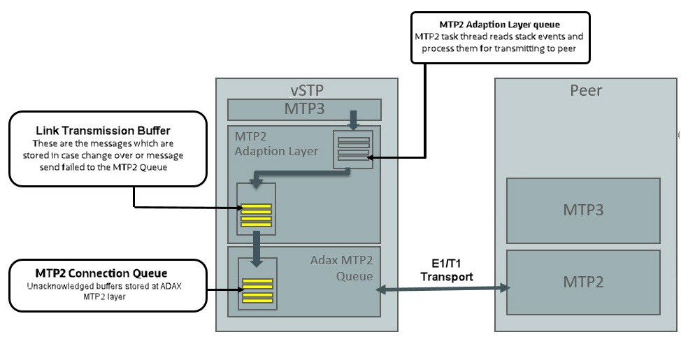
2.9.5.3 MTP2 Link Congestion
MTP2 Link congestion is derived from the utilization of link transmission buffers maintained at MTP2 adaption layer and unacknowledged messages buffered at MTP2 connection queue.
Table 2-9 Congestion Threshold Values
| Congestion Level | Threshold Level | Onset Threshold | Clear Threshold |
|---|---|---|---|
| 3 | Critical | 95 | 90 |
| 2 | Major | 85 | 80 |
| 1 | Minor | 60 | 50 |
Based on the congestion level of Links, congestion level of Linkset is derived as per the following formula:
Congestion Level of Linkset = Max (Congestion level of all Links in the linkset )
Based on congestion Level of linkset, congestion level of RSPs with route having the same linkset are derived.
MTP2 Link Congestion Detection
For MTP2 Link Congestion detection, the congestion threshold values are used as per Congestion Threshold Values.
(Link TPS * 2 ) base is used for the base calculation of the congestion detection.
If sum of Link transmission buffer and MTP2 connection buffer queue utilization percentage is above configured threshold level, then the link is considered as congested.
Example:
Te following figure describes the MTP2 link congestion detection:
Figure 2-5 MTP2 Link Congestion Detection
2.9.5.4 Remote Processor Outage Handling
Remote processor outage (RPO) is a procedure where the processor outage status of the remote signaling point is communicated to the local signaling point.
Handling of RPO
- A notification message is initiated by the RSP to MTP2 layer.
- After receiving the notification, the MTP2 layer stops sending data messages to remote point and sets the Link state to out of service. It send RPO indication to MTP3 layer.
-
MTP3 layer receives the RPO notification and it starts the change over procedure. If MTP2 received PO recovered message, it send the indication to MTP3 Layer. Once RPO recovered message received at MTP3 Layer , it marks the link as available and initiate the change back procedure.
-
When link comes in-service state, MTP2 starts data message transfer to remote end.
2.9.6 TDM Support Feature Configuration
This section provides procedures to configure the TDM support.
TDM support is configured using the vSTP managed objects. The MMI API contains details about the URI, an example, and the parameters available for each managed object.
2.9.6.1 MMI Managed Objects for TDM Support
MMI information associated with TDM Support is accessed from a DSR NOAM or SOAM from .
Once the MMI API Guide displays, use the application navigation to locate specific vSTP managed object information.
The following table lists the managed objects and operations supported for vSTP TDM Support feature:
Table 2-10 vSTP TDM Support Managed Objects and Supported Operations
| Managed Object Name | Supported Operations |
|---|---|
| interfacemappings | Insert, Update, Delete |
| mtp2board | Display |
| linksets | Insert, Update, Delete |
| links | Insert, Delete |
| mtp3timersetconfigs | Insert, Update, Delete |
| mtp2timersetconfigs | Insert, Update, Delete |
interfacemappings - Insert, Update, Delete
MTP2 Interface Mapping (eLynx Card)
This MO configures the interface channel for eLynx Card. This channel is specified while configuring the MTP2 link.
Sample JSON to configure MTP2 interface channel named channel1:
{
            "boardType": "MTP2_BOARD_TYPE_ELYNX",
            "channelName": “elynx1",
            "ecm": "LINK_ECM_BASIC",
            "encodingScheme": "ENCODE_NONE",
            "framing": "FRAMING_SF",
            "hostName": “velynx-so1mp1",
            "linkTiming": "LINK_TIME_NONE",
            "linkType": "T1_hsl",
            "ll": 133,
            "minSuRate": 1000,
            "port": 4,
            "speed": "Hsl_1536k"
}
To display, execute the MMI Client command from an active SOAM:
/vstp/interfacemappings/channel1Example Output:
{
 	     "boardType": "MTP2_BOARD_TYPE_ELYNX",
            "channelName": “elynx1",
            "ecm": "LINK_ECM_BASIC",
            "encodingScheme": "ENCODE_NONE",
            "framing": "FRAMING_SF",
            "hostName": “velynx-so1mp1",
            "linkTiming": "LINK_TIME_NONE",
            "linkType": "T1_hsl",
            "ll": 133,
            "minSuRate": 1000,
            "port": 4,
            "speed": "Hsl_1536k"
}
MTP2 Interface Mapping (ADAX Card)
This MO configures the interface channel for ADAX Card. This channel is specified while configuring the MTP2 link.
Sample JSON to configure MTP2 interface channel named channel1:
{
    "boardType": "MTP2_BOARD_TYPE_ADAX",
    "channelName": "chan149",
    "hostName": “vadax-so1mp1",
    "linkType": "E1",
    "port": 3,
    "sequenceLength": "7_BIT ",
    "speed": "Lsl_64k",
    "timeSlot": 20
}
To display, execute the MMI Client command from an active SOAM:
/vstp/interfacemappings/channel1Example Output:
{
    "boardType": "MTP2_BOARD_TYPE_ADAX",
    "channelName": "chan149",
    "hostName": “vadax-so1mp1",
    "linkType": "E1",
    "port": 3,
    "sequenceLength": "7_BIT ",
    "speed": "Lsl_64k",
    "timeSlot": 20
}
mtp2board - Display
This REST MO displays the TDM PCIe card configuration on the VSTP MP. Sample output for MTP2 Board Display :
{
    "boardType": "HDC3",
    "elt1Port": "4",
    "ethPort": "0",
    "machVer": "4",
    "mrl": "3",
    "pormVer": "15",
    "serialNum": "2558",
    "sourceNode": "rAdax-so1mp1"
}
linksets - Insert, Update, Delete
This MO configures the Linkset for a given Adjacent Point Code.
Example JSON to configure Linkset with MTP2 Adapter:
{
"enableBroadcastException": false,
"linkTransactionsPerSecond": 100,
"localSignalingPointName": "LSP1",
"name": "Linkset1",
"remoteSignalingPointName": "RSP1",
"type": "Mtp2"
}
To display, execute the MMI Client command from an active SOAM:
Note:
Provide name of the link in <LinkName>./vstp/linksets/<LinkName>
Example Output:
{
"cgGtmod": false,
"configurationLevel": "135",
"enableBroadcastException": false,
"gttmode": "Fcd",
"ituTransferRestricted": false,
"linkTransactionsPerSecond": 100,
"localSignalingPointName": "LSP1“,
"mtpScrEventLog": true,
"mtpScrSetName": "Set3",
"mtpScrTestMode": false,
"name": "Linkset1",
"remoteSignalingPointName": "RSP1",
"type": "Mtp2"
}
links - Insert, Update, Delete
This MO configures link with the given channel.
Sample JSON to configure MTP2 link with MTP2 channel configuration channel1
{
    "channelName": "channel1",
    "linksetName": " Linkset1 ",
    "name": “Ls1Lnk13",
    "signalingLinkCode": 1
}
To display, execute the MMI Client command from an active SOAM:
/vstp/links/<LinkName>
Example Output:
{
    "channelName": " channel1 ",
    "configurationLevel": "24",
    "linksetName": " Linkset1 ",
    "name": " Ls1Lnk13 ",
    "signalingLinkCode": 1
}
mtp3timersetconfigs - Insert, Update, Delete
{
   "name": "config1",
    "sltT1Timer": 8000,
    "sltT2Timer": 35000,
    "sltT17Timer": 2000,
    "t10Timer": 25000,
    "t11Timer": 3000,
    "t12Timer": 800,
    "t13Timer": 800,
    "t15Timer": 600,
    "t16Timer": 800,
    "t17Timer": 800,
    "t18Timer": 3000,
    "t1Timer": 800,
    "t2Timer": 800,
    "t23Timer": 180000,
    "t3Timer": 800,
    "t4Timer": 600,
    "t5Timer": 600,
    "t6Timer": 800,
    "t8Timer": 800
}
/vstp/mtp3TimersetConfig -v POST -r /<Absolute path>/<File Name>
Example Output:
{
  "data": true,
	 "links": {},
	 "messages": [],
	 "status": true
  }
/vstp/mtp3TimersetConfig -v PUT -r /<Absolute path>/<File Name>
Example Output:
{
 	"data": true,
	 "links": {},
	 "messages": [],
	 "status": true
      }
/vstp/mtp3TimersetConfig/<set name> -v DELETE
Example Output:
No output returned by URI: https://localhost/mmi/dsr/v4.0/vstp/mtp3TimersetConfig/Mtp3Config1? for 'DELETE' operation
To display, execute following command on Active SOAM:
/ vstp/mtp3TimersetConfig{
"data": [
{
"name": "config1",
"sltT1Timer": 8000,
"sltT2Timer": 35000,
"sltT17Timer": 2000,
"t10Timer": 25000,
"t11Timer": 3000,
"t12Timer": 800,
"t13Timer": 800,
"t15Timer": 600,
"t16Timer": 800,
"t17Timer": 800,
"t18Timer": 3000,
"t1Timer": 800,
"t2Timer": 800,
"t23Timer": 180000,
"t3Timer": 800,
"t4Timer": 600,
"t5Timer": 600,
"t6Timer": 800,
"t8Timer": 800
}
],
"links": {},
"messages": [],
"status": true
}
mtp2timersetconfigs - Insert, Update, Delete
{
            "name": "Set1",
            "t1Timer": 5000,
            "t2Timer": 5000,
            "t3Timer": 1000,
            "t4EmergencyTimer": 200,
            "t4NormalTimer": 840,
            "t5Timer": 40,
            "t6Timer": 1000,
            "t7Timer": 200
}
/vstp/mtp2timersetconfigs -v POST -r /<Absolute path>/<File Name>
Example Output:
{
 	"data": true,
	 "links": {},
	 "messages": [],
	 "status": true
      }
/vstp/vstp/mtp2timersetconfigs -v PUT -r /<Absolute path>/<File Name>
Example Output:
{
 	"data": true,
	 "links": {},
	 "messages": [],
	 "status": true
      }
/vstp/mtp2timersetconfigs/<set name> -v DELETE
Example Output:
No output returned by URI: https://localhost/mmi/dsr/v4.0/vstp/mtp2timersetconfigs/config1? for 'DELETE' operation
To display, execute following command on Active SOAM:
/vstp/mtp2timersetconfigs
  {
 "data": [
{
    "name": "Set1",
    "t1Timer": 5000,
    "t2Timer": 5000,
    "t3Timer": 1000,
    "t4EmergencyTimer": 200,
    "t4NormalTimer": 840,
    "t5Timer": 40,
    "t6Timer": 1000,
    "t7Timer": 200
}
    ],
    "links": {},
    "messages": [],
    "status": true
}
2.9.6.2 TDM Support Alarms and Measurements
Alarms and Events
The following table lists the Alarms and Events specific to the TDM support for vSTP:
| Alarm/ Event ID | Name |
|---|---|
| 70001 | Link Down |
| 70005 | Link Unavailable |
| 70009 | Link Congested |
| 70102 | MTP3 Ingress Link MSU TPS Crossed |
| 70103 | MTP3 Egress Link MSU TPS Crossed |
| 70104 | MTP3 Ingress Link Management TPS Crossed |
| 70084 | VSTP MTP2 Transmission and Retransmission Buffer Utilization |
| 70220 | MTP2 Link admin state change |
| 70221 | Failed to send message to TDM driver |
| 70222 | Failed to receive message from TDM driver |
| 70223 | MTP2 link operational state changed |
| 70224 | MTP2 link failed |
| 70225 | MTP2 Ingress message discarded |
| 70226 | MTP2 Egress message discarded |
| 70227 | Received Remote Out Of Service on MTP2 link |
For more details related to Alarms and Events, refer to Alarms and KPIs Reference document.
Measurements
| Measurement ID | Measurement Name |
|---|---|
| 21800 | VstpMtp2LnkOutageDuration |
| 21804 | VstpMtp2LnkAvailableDuration |
| 21805 | VstpMtp2RxLnkMSUOctets |
| 21806 | VstpMtp2RxLnkMSUOctetsForGTT |
| 21807 | VstpMtp2TxLnkMSUOctets |
| 21808 | VstpMtp2Priority0MsuDiscarded |
| 21809 | VstpMtp2Priority1MsuDiscarded |
| 21810 | VstpMtp2Priority2MsuDiscarded |
| 21811 | VstpMtp2Priority3MsuDiscarded |
| 21813 | VstpMtp2RxLnkMSUForGTT |
| 21816 | VstpMtp2LnkMaintUsage |
| 21821 | VstpMtp2LnkCO |
| 21823 | VstpMtp2OOSDuration |
| 21824 | VstpMtp2LnkRPODuration |
| 21826 | VstpMtp2LnkCumlInhibitDuration |
| 21827 | VstpMtp2LnkRemoteInhibitDuration |
| 21828 | VstpMtp2RxLnkMSUError |
| 21835 | VstpMtp2LnkTotalOutage |
| 21836 | VstpMtp2LnkTotalRPOCount |
| 21839 | VstpMtp2RxLnkMSUInError |
| 21840 | VstpMtp2LnkTotalActiveDuration |
| 21841 | VstpMtp2LnkTotalUnAvailableDuration |
For more details related to measurements, refer to Measurement Reference document.
2.9.7 Troubleshooting
The following are the troubleshooting scenarios for TDM support:
- The E1/T1 links do not align
properly
Do the following to troubleshoot:
- Verify that the cable is not faulty.
- Verify the cable connections.
- Verify that the Adax HDC3 card configuration (in QCXfile) is as per the Interface Mapping configuration.
- Ensure that the Adax HDC3 card timing source configuration is correct. In case of SUERM errors, modify the timing source.
- Frequent toggling of the E1/T1
Links
Do the following to troubleshoot:
-
Verify that the point codes associated with the linkset are correct.
- Verify that the link alignment and SLTM timers are correct.
-
-
Adax HDC3 Card is not
detected on a vSTP MP VM
Do the following to troubleshoot:
-
Check that the vSTP MP VM and the Adax HDC3 card are co-located on same host machine.
- Check the Adax HDC3
RPMs.
The following RPMs are required on vSTP MP VM for configuring Adax HDC3 Card:
- Adax-LiS-2.21.8-1-RedHat-6.10-x86-64bit.rpm
- Adax-hdc-1.79-1-RedHat-6.10-x86-64bit-LiS2.21.8-MAJ234.rpm
- Adax-qcx-1.25-1-Linux-x86-64bit.rpm
-
Note:
The vSTP MP VM and the Adax HDC3 card must be co-located on same host machine.2.9.8 Dependencies
The TDM support for vSTP has no dependency on any other vSTP operation.
Points to Consider
The following points must be considered while configuring eLynx Card:
- The eLynx card support only E1 traffic.
- eLynx is supported when installed in Oracle X8-2 and X8-2L servers.
- A maximum of 4 eLynx cards per server are supported.
- PCI slots 5 and 6 are not supported for eLynx on the Oracle X8-2L servers.
- Only 1 eLynx card per Message Processor (MP) is supported.
- The eLynx card is rated to process a maximum of 10K messages per second. If the
ingress message rate crosses the 10K per second limit, the eLynx card may go
into local congestion. This causes all the links on the eLynx card to go out of
service until the congestion condition abates. Once the congestion condition is
cleared, the eLynx card starts the link alignment process again.
If the congestion condition persists for too long, the eLynx card can be impacted severely. some links may not recover automatically. If this happens, then the eLynx card needs to be reset or reloaded to recover.
The following points must be considered while configuring ADAX Card:
- After each upgrade ADAX Configurations has to be installed afresh.
- The J1 and ATM interfaces are not supported.
- Single ADAX HDC3 card cannot be accessed from Multiple VSTP MP VMs.
- The ADAX HDC3 driver and required components are not packaged with Standard DSR ISO. These components and RPMs have to be installed separately.
2.10 Scalability
vSTP supports 10K MPS SS7 traffic capacity at the system level. This allows vSTP to support redundancy and diversity at the signaling interfaces. That is, more than one active STP-MP server can support signaling interfaces pointing toward the same remote signaling point.
Topology
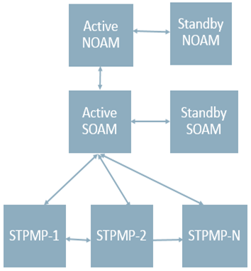
vSTP supports two topologies.
- Only STP-MP servers in a site
Figure 2-6 Only STP-MP Site
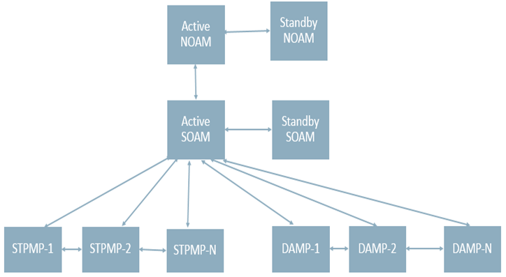
- STP-MP and DA-MP servers in a site
Figure 2-7 STP-MP and DA-MP in a Site
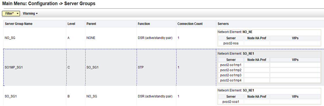
Server Group Configuration
The following table shows multiple STP servers in one server group.
Figure 2-8 Multiple STP Servers in a Server Group
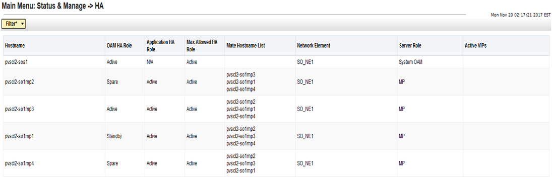
HA Status
The HA role needs to be active for all STP servers as shown in the following table:
Figure 2-9 HA Role for STP Servers
2.11 In-Sequence Delivery of Class 1 UDT Messages
The In-Sequence Delivery of Class 1 UDT Messages provides
for the sequencing for both UDT and XUDT Class 1 MSUs. All UDT/XUDT Class 1
messages are routed out in the same order that they were received. To enable
the sequencing of UDT/XUDT Class 1 messages, the
class1seq parameter value of the SCCP
options using MMI is set to
on.
When the
class1seq parameter value is
off, load sharing of the UDT/XUDT Class
1 messages is performed using the load sharing configuration in the MAP and MRN
tables. The delivery of the UDT/XUDT Class 1 messages in sequence is not
guaranteed.
If the messages are not in the correct sequence when they arrive, they are not delivered to the next node in the correct sequence. Message re-sequencing is the responsibility of the originating and destination nodes.
GT-routed Class 0 UDT/XUDT messages are not sequenced.
2.12 SLS Rotation
The Signaling Link Selection(SLS) Rotation feature facilitates a proper distribution of SLS values to provide a good distribution of traffic and load sharing across links and linksets.
In many cases, MSCs, switches and other originating nodes do not send an adequate distribution of SLS values, which results in a poor distribution of traffic across links.
For example, in case of ITU ISUP messages, SLS is obtained from the lower 4 bits of CIC field representing the circuit that is being used. CIC selection can be determined based on an odd or even method where SSP uses either all the odd CICs or all the even CICs to help prevent glaring. This causes Least Significant Bit (LSB) of the SLS to be fixed (0 or 1), which means SSP sends either odd or even SLS. As a result, the transit nodes (STPs) do not achieve a good distribution of traffic across links.
For combined linkset in ANSI and ITU MTP protocols, the LSB of the SLS is used to load share between linksets of a combined linkset and the remaining SLS bits are used to distribute traffic across different links within a linkset. Since, STP receives improper distribution of SLS values (LSB either 0 or 1) the STPs cannot perform proper load sharing across linksets and links of a linkset.
Similarly for single linkset, STPs cannot perform proper load sharing across all links of a linkset, because of receiving improper distribution of SLS values (LSB either 0 or 1).
To overcome this problem, the SLS Rotation feature provides the following SLS Rotation options to users:
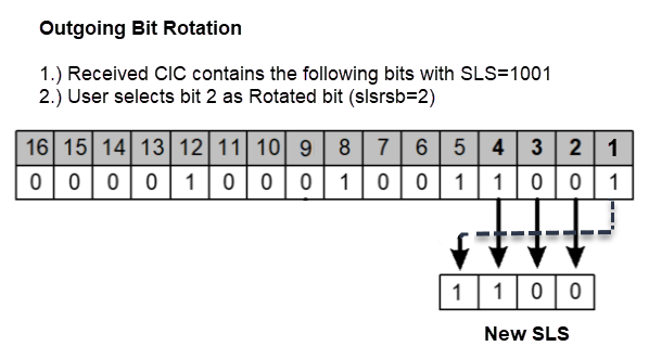
2.12.1 Outgoing Bit Rotation
If the Outgoing Bit Rotation option is configured, the vSTP rotates the 4 bits of SLS according to the outgoing linkset. Thus, changing the LSB of the SLS.
This option can be used as a solution to the problem of vSTP selecting same linkset of a combined linkset. Bit rotation can be used on a per linkset basis to ensure that vSTP does not use static LSB (always 0 or always 1) in the received SLS for linkset selection. It is applicable to all ITU messages.
-
If bit position 4 is selected (slsrsb =4) for the outgoing linkset, then bit locations 4 3 2 1 are rotated to positions 3 2 1 4.
For example, SLS = 0110 becomes Rotated SLS = 1100
-
If bit position 3 is selected (slsrsb =3) for the outgoing linkset, then bit locations 4 3 2 1 are rotated to positions 2 1 4 3.
For example, SLS = 0110 becomes Rotated SLS = 1001
-
If bit position 2 is selected (slsrsb =2) for the outgoing linkset, then bit locations 4 3 2 1 are rotated to positions 1 4 3 2.
For example, SLS = SLS = 0110 becomes Rotated SLS = 0011
-
If bit position 1 is selected (slsrsb =1) for the outgoing linkset, then no rotation is performed since bit 1 is the existing LSB. Bit 1 is the default value.
For example, SLS = 0110 remains 0110 only.
Outgoing Bit Rotation Example:
The following figure shows an example of Outgoing Bit Rotation:
Figure 2-10 Example: SLS Outgoing Bit Rotation
Note:
-
After the SLS is rotated then the existing algorithm for selecting a linkset and signaling link is performed and the message is sent out on the selected link. Note that the SLS is modified only for the link selection algorithm and is not modified in the outgoing message.
-
For ITU ISUP messages, SLS is obtained from the lower 4 bits of the CIC field representing the circuit being used. Use of Outgoing bit rotation alone does not guarantee an even distribution of ITU-ISUP messages across all links within a linkset. The vSTP uses all 4 bits of the SLS to determine the actual link to route messages. Since the static bit is simply rotated within the SLS, all possible values of the SLS field will still not be realized. A second option, "Use of Other CIC Bit", must be applied to guarantee even distribution across all links within the linkset.
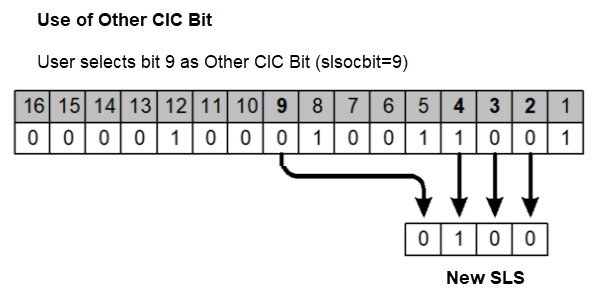
2.12.2 Use of Other CIC Bit
If the Use of Other CIC Bit option is selected, then vSTP derives SLS as per the following rule:
- The bits at positions 2 to 4 of the CIC serve as three lower bits of SLS.
- The Most Significant Bit (MSB) of SLS can be any bit from the bits at position 5 to 16 of the CIC.
This option can be used as a solution to the problem of vSTP not sharing load between all links within a linkset. It is applicable to ITU ISUP messages.
The Use of Other CIC Bit option applies to all ITU ISUP MSUs based on the combination of slsocbEnabled and slsocbit parameters. User needs to set the value of the slsocbEnabled parameter in m3rloptions MO to true and configure slsocbit in Linkset MO to specify the bit (bits at position 5 through 16 of CIC) to be used as the other CIC bit . The specified bit acts as the MSB of the new SLS and bits at position 2 through 4 of the received CIC become the LSBs of the new SLS. Once the SLS is generated, the existing algorithm for selecting a linkset and signaling link is performed and message is sent out on the selected link.
Use of Other CIC Bit Example:
Figure 2-11 Example: SLS Use of Other CIC Bit
2.12.3 Incoming Bit Rotation
If the Incoming Bit Rotation option is selected, then vSTP rotates the 4 bits of ITU SLS and 5 or 8 bits of ANSI SLS according to the incoming linkset. Thus, changing the LSB of the SLS.
This option provides additional capability to fairly distribute traffic across links and linksets, however it still does not guarantee an even distribution of messages for all set of input SLS values. It is applicable to all ITU and ANSI messages.
- ITU Messages
For ITU messages, the SLS value is only 4 bits and all 4 bits are considered for rotation. The Incoming Bit Rotation is applied on ITU MSUs based on the combination of islsrsb and islsbrEnabled parameters. User needs to set the value of the islsbrEnabled parameter in m3rloptions MO to true and configure islsrsb in Linkset MO to specify the bit to be used as LSB. This rotation affects the 4 bits of SLS selection in the following manner:
-
If bit position 4 is selected (islsrsb =4) for the incoming linkset, then bit locations 4 3 2 1 are rotated to positions 3 2 1 4.
For example, SLS = 1101 becomes Rotated SLS = 1011
-
If bit position 3 is selected (islsrsb =3) for the incoming linkset, then bit locations 4 3 2 1 are rotated to positions 2 1 4 3.
For example, SLS = 1110 becomes Rotated SLS = 1011
-
If bit position 2 is selected (islsrsb =2) for the incoming linkset, then bit locations 4 3 2 1 are rotated to positions 1 4 3 2.
For example, SLS = 0110 becomes Rotated SLS = 0011
-
If bit position 1 is selected (islsrsb =1) for the incoming linkset, then no rotation is performed since bit 1 is the existing LSB. Bit 1 is the default value.
For example, SLS = 0110 remains 0110 only.
-
- ANSI Messages
The Incoming Bit Rotation is applied on ANSI messages as per the combination of the following parameters.
Table 2-11 Parameters used for Incoming Bit Rotation of ANSI
Parameter Name Description islsbrEnabled User needs to set the value of the islsbrEnabled parameter in m3rloptions MO to true. asls8 Specifies if the adjacent node is sending MSUs with 5 or 8 bits SLS. This parameter value is configured in Linkset MO.
rsls8 The inclusion of 5 or 8 bits of SLS in the rotation depends on the value of the rsls8 parameter in Linkset MO. - If the value is true: 8 bits SLS is considered for rotation
- If the value is false: the least significant 5 bits of SLS are considered for rotation
slscnv and slsci The combination of both these parameters with asls8 decides if 5 to 8 bits SLS conversion option is applied on incoming 5 bits SLS or not.
slscnv is configured in m3rloptions MO and slsci is configured in Linkset MO.
islsrb Configure islsrsb in Linkset MO to specify the bit to be used as LSB. The combination of values provided to these parameters on incoming linkset decides the SLS bits (5 or 8) to be considered for rotation. The following table describes the combination of parameter values with respective rotation rule:
Note:
In below table, the values of CNV represents combination of the following parameters:CNV = YES : (SLSCNV=On) or (SLSCNV= PerLs and SLSCI on the outgoing linkset =true)
CNV=NO : (SLSCNV=Off) or (SLSCNV= PerLs and SLSCI on the outgoing linkset =false)
Table 2-12 Rules applied for Incoming Bit Rotation of ANSI
Rule asls8 rsls8 islsbr CNV Incoming SLS Bits Rotation (islsbr) 1 false false 1-5 NO The least significant 5 bits of SLS will be considered for rotation. 2 false false 1-5 YES The least significant 5 bits of SLS will be considered for rotation. 3 false true 1-8 NO No ISLSBR will be performed. Note: Enable 5-bit to 8-bit ANSI SLS conversion on outgoing linkset to perform ISLSBR
4 false true 1-8 YES The 8-bit SLS value obtained after 5-8 bit conversion is considered for rotation. 5 true false 1-5 Has No Impact The least significant 5 bits of SLS will be considered for rotation. 6 true true 1-8 Has No Impact The 8-bits SLS will be considered for rotation.
Incoming Bit Rotation Example:
| Incoming ANSI SLS | RSLS8 on incoming linkset | Chosen LSB | Rotated SLS | Applied Rule from Table 2-11 |
|---|---|---|---|---|
| 11000110 | false | 2 | 11000011 | 5 |
| 01011110 | true | 7 | 01111001 | 6 |
| 10010 | false | 4 |
10101010
Note: The highlighted bits indicates the 3 new SLS bits introduced by 5-bit ANSI to 8-bit ANSI SLS conversion. |
2 |
| 10010 | true | 8 |
01100101
Note: The highlighted bits indicates the 3 new SLS bits introduced by 5-bit ANSI to 8-bit ANSI SLS conversion. |
4 |
| 01101 | false | 4 | 10101 | 1 |
| 01101 | true | 7 | No Rotation | 3 |
2.12.4 Random SLS
If the Random SLS option is selected, then vSTP randomly generates SLS values. This randomly generated SLS value is then used to select an outgoing linkset and a link in order to achieve load balancing.
This option is applicable to all the ITU SCCP (Class 0 and Class 1), ANSI SCCP Class 0, and ANSI ISUP messages.
For this option, the system-wide randsls parameter provides the flexibility to provision Random SLS value as Off, Class0, All (Class0 & Class1), or PerLs . The Per-Linkset randsls parameter can provide the additional flexibility to apply Random SLS generation on per linkset basis. User shall be able to provision specific linksets with Random SLS value as Off, Class0, or All (Class0 & Class1).
For ANSI MSUs, randsls is applied based on the configuration for ingress linkset . For ITU MSUs, it is applied based on the configuration for egress linkset .
- ITU Messages
For ITU, this option is available system-wide as well as on per linkset basis. The following table describes the rules applied on incoming MSU when Random SLS option is selected for ITU:
Table 2-13 Rules applied for Random SLS for ITU
System-wide randsls ( in m3rloptions) randsls on outgoing linkset Random SLS Off Has No Impact Random SLS is not applied on any ITU message. All Has No Impact Random SLS is applied on all ITU SCCP messages. Class0 Has No Impact Random SLS is applied on all ITU SCCP CLASS0 messages. PerLs Off Random SLS is not applied on any ITU message going through this linkset . PerLs All Random SLS is applied on all ITU SCCP messages going through this linkset . PerLs Class0 Random SLS is applied on all ITU SCCP CLASS0 messages going through this linkset . - ANSI Messages
For ANSI, this option is available on per linkset basis only. The following table describes the rules applied on incoming MSU when Random SLS option is selected for ANSI:
Table 2-14 Rules applied for Random SLS for ANSI
System-wide randsls ( in m3rloptions) randsls on outgoing linkset Random SLS Off Has No Impact Random SLS is not applied on any ANSI message. All Has No Impact Random SLS is not applied on any ANSI message. Class0 Has No Impact Random SLS is not applied on any ANSI message. PerLs Off Random SLS is not applied on any ANSI message going through this linkset . PerLs All Random SLS is applied on ANSI SCCP Class0 and ISUP messages going through this linkset . PerLs Class0 Random SLS is applied on all ANSI SCCP CLASS0 messages going through this linkset .
Note:
The SLS modified using the above options is used for internal linkset and link selection only. The actual SLS field of the message does not get modified. Therefore, the SLS value received by vSTP remains the SLS value sent out by the vSTP.2.12.5 Combining SLS Rotation Options
In order to provide an even distribution of ITU and ANSI messages sent by M3RL, vSTP allows to combine the Random SLS, Use of Other CIC Bit, Incoming Bit Rotation, and Outgoing Bit Rotation options in the following manner:
ITU Messages
If a user activates the above options for a given linkset, then the ITU SLS field is processed in the following order:
-
If the randsls parameter value is set as ON, then 8-bit random SLS is generated.
Note:
Random SLS of ITU is based on either the global option or outgoing linkset parameter. For more details on Random SLS, see SLS Rotation. -
If the global slscnv or slsci parameters for outgoing linkset are ON, then the 4-bits ITU SLS is converted to 8-bits SLS using 4-to-8 Bit SLS Conversion option.
-
If it is an ITU-ISUP message, then the least-significant 4-bits of the modified SLS are modified using the Other CIC Bit option.
-
The least-significant 4-bits of the modified SLS are modified using Incoming Bit Rotation or Outgoing Bit Rotation.
-
The modified SLS is used by the existing linkset and link selection algorithms to select a linkset and link.
-
The Message is sent out to the selected link containing the original and unmodified SLS field.
For ANSI Messages
If a user activates these options for a given linkset, then the ANSI SLS field is processed in the following order:
-
If the randsls parameter value is set as ON, then 8-bit random SLS is generated.
Note:
Random SLS of ANSI is based on the incoming linkset parameter with the value of global option set as is PerLs. For more details on Random SLS, see SLS Rotation. -
If RANDSLS is applied and the system-wide slsreplace parameter value is true, then the randomly generated SLS is replaced in the MSU and Step 5 is executed.
-
If the global slscnv or slsci parameters for outgoing linkset are ON, then the 5-bits ANSI SLS is converted to 8-bits SLS using 5-to-8 Bit SLS Conversion option.
-
If Random SLS is not applied, then the converted SLS is modified using the Incoming Bit Rotation option.
-
The modified SLS is used by the existing linkset and link selection algorithms to select a linkset and link.
-
The SLS is modified using standard 5th bit rotation, replaced in the MSU and sent out to selected link.
2.12.6 SLS Conversion
The Signaling Link Selection(SLS) conversion feature allows vSTP to convert the SLS bits of ITU and ANSI messages. The SLS conversion is applicable to all the MTP-Routed and GT-Routed MSUs.
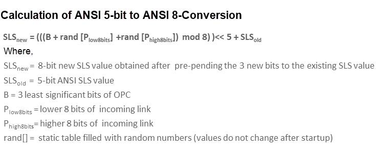
2.12.6.1 ANSI 5-bit to ANSI 8-bit SLS Conversion
The ANSI 5-bit to ANSI 8-bit SLS Conversion enables a user to perform 5-bit ANSI conversion to 8-bit ANSI. If this conversion option is configured, then the SLS is converted from 5-bit to 8-bit ANSI. The conversion is performed during routing, between linkset and link selection. SLS rotation follows the link selection.
The messages, which satisfy the following conditions can only be converted from 5-bit to 8-bit SLS:
-
The incoming and outgoing linksets are SS7 ANSI.
-
The incoming linkset has ASLS8=NO .
-
The value of the slsci parameter is YES and the slscnv parameter is PERLs or ON for the outgoing linkset.
-
The 3 most significant bits of the SLS are 000.
If the above conditions are fulfilled, then only the new SLS value is calculated as per the following figure:Figure 2-12 ANSI 5-bit to ANSI 8-bit SLS Conversion
2.12.6.2 ITU to ANSI SLS Conversion
The ITU to ANSI SLS Conversion enables a user to perform 4-bit ITU to 5-bit ANSI conversion. If this conversion option is configured, then the SLS is converted from 4-bit ITU to 5-bit ANSI.
If ITU 4-bit SLS is ABCD then the ANSI 5-bit SLS is calculated as D (~D) ABC.
This conversion can further be followed by ANSI 5-bit to ANSI 8-bit SLS Conversion in order to achieve more randomization for linkset or link selection during the network conversion.
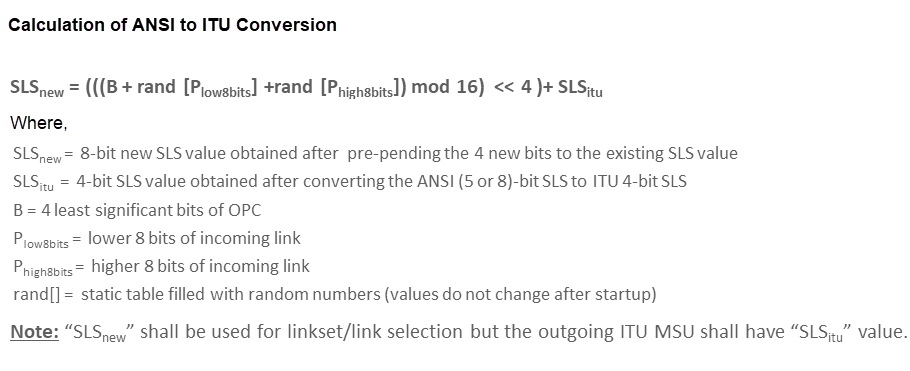
2.12.6.3 ANSI to ITU SLS Conversion
The ANSI to ITU SLS Conversion enables a user to perform 5-bit or 8-bit ANSI to 4-bit ITU conversion.
Figure 2-13 ANSI to ITU SLS Conversion
2.12.6.4 Interaction between SLS Conversion Algorithms
This section describes the interaction of SLS conversion algorithms during network conversion:
- ITU to ANSI Conversion
The following table describes the interaction between different SLS conversion algorithms and the associated outgoing SLSs for ITU to ANSI Conversions:
Table 2-15 Interaction between SLS Conversion Algorithms - (ITU to ANSI Conversion)
randsls 5-bit to 8-bit conversion islsbr slsreplace Bits for Linkset /Link Selection Outgoing SLS No No No Has no impact 5 bits obtained after 4-bit ITU to 5-bit ANSI Conversion 5 bits obtained after 4-bit ITU to 5-bit ANSI Conversion No No Yes Has no impact Rotated 5 bits 5 bits obtained after 4-bit ITU to 5-bit ANSI Conversion No Yes No Has no impact Converted 8 bits Converted 8 bits No Yes Yes Has no impact Converted and rotated 8 bits Converted 8 bits Yes No No No Random 8 bits 5 bits obtained after 4-bit ITU to 5-bit ANSI Conversion Yes No No Yes Random 8 bits Random 8 bits Yes No Yes Has no impact NA NA Yes Yes No No Converted 8 bits Converted 8 bits Yes Yes No Yes NA NA Yes Yes Yes Has no impact NA NA As per the above table, the following are the key points during ITU to ANSI conversion:
- The randsls and islsbr parameters are mutually exclusive.
-
The randsls and 5-bit to 8-bit SLS conversion are mutually exclusive when slsreplace flag is ON.
-
The slsbr parameter is not applicable for ITU to ANSI network conversions because in case of these conversions, messages are already converted to ANSI by the time slsbr is applied. Also, slsbr is applicable only for ITU MSUs.
-
During ITU to ANSI network conversion, the ingress linkset is ITU, hence the value of asls8 will always be No. Therefore, if randsls is applied after ITU to ANSI network conversion, the outgoing SLS will be of 5 or 8 bits, depending on the values of the m3rloptions,slsreplace and LINKSET(EGRESS), slsci /m3rloptions, or slscnv parameters.
- ANSI to ITU Conversion
The following table describes the interaction between different SLS conversion algorithms and the associated outgoing SLSs for ANSI to ITU Conversions:
Table 2-16 Interaction between SLS Conversion Algorithms - (ANSI to ITU Conversion)
| randsls | 4-bit to 8-bit conversion | islsbr/slsbr | Bits for Linkset /Link Selection | Outgoing SLS |
|---|---|---|---|---|
| No | No | No | 4 bits obtained after 5-bit to 4-bit or 8-bit to 4bit ANSI-ITU SLS Conversion | 4 bits obtained after 5-bit to 4-bit or 8-bit to 4bit ANSI-ITU SLS Conversion |
| No | No | Yes | Rotated 4 bits | 4 bits obtained after 5-bit to 4-bit or 8-bit to 4bit ANSI-ITU SLS Conversion |
| No | Yes | No | Converted 8 bits | 4 bits obtained after 5-bit to 4-bit or 8-bit to 4bit ANSI-ITU SLS Conversion |
| No | Yes | Yes | Converted and rotated 8 bits | 4 bits obtained after 5-bit to 4-bit or 8-bit to 4bit ANSI-ITU SLS Conversion |
| Yes | No | No | Random 8 bits | 4 bits obtained after 5-bit to 4-bit or 8-bit to 4bit ANSI-ITU SLS Conversion |
| Yes | No | Yes | NA | NA |
| Yes | Yes | No | NA | NA |
| Yes | Yes | Yes | NA | NA |
As per the above table, the following are the key points during ANSI to ITU conversion:
- The randsls and islsbr/slsbr parameters are mutually exclusive.
-
The randsls and 4-bit to 8-bit SLS conversion are mutually exclusive.
2.12.7 SLS Rotation Feature Configuration
This section provides procedures to configure the SLS Rotation feature.
SLS Rotation requires the vSTP managed objects. The MMI API contains details about the URI, an example, and the parameters available for each managed object.
2.12.7.1 MMI Managed Objects for SLS Rotation
MMI information associated with SLS Rotation functionality is accessed from a DSR NOAM or SOAM from .
Once the MMI API Guide displays, use the application navigation to locate specific vSTP managed object information.
The following table lists the managed objects and operations supported for vSTP SLS Rotation feature:
Table 2-17 vSTP SLS Rotation Managed Objects and Supported Operations
| Managed Object Name | Supported Operations |
|---|---|
| m3rloptions | Update |
| linksets | Insert, Update, Delete |
m3rloptions - Display, Update
Execute the following command on Active SOAM to display table data:
/vstp/m3rloptions
Sample Output:
{
"cnvAInat": 1,
"cnvCgda": true,
"cnvCgdi": true,
"cnvCgdn": false,
"cnvCgdn24": false,
"cnvClgItu": "Off",
"gtCnvDflt": true,
"islsbrEnabled": false,
"lsOnHoldTimer": 60,
"randsls": "Off",
"slsRotation": true,
"slscnv": "Off",
"slsocbEnabled": false,
"slsreplace": false,
"sltT1Timer": 12000,
"sltT2Timer": 30000,
"sparePCSupportEnabled": true,
"t10Timer": 30000,
"t11Timer": 30000,
"t15Timer": 3000,
"t16Timer": 1400,
"t17Timer": 2000,
"t18Timer": 10000,
"t1Timer": 800,
"t2Timer": 1400,
"t3Timer": 800,
"t4Timer": 800,
"t5Timer": 800,
"t6Timer": 800,
"t8Timer": 800
)
{
        "randsls": "Off",
        "slsRotation": true,
        "slscnv": "Off",
        "slsocbEnabled": false,
        "slsreplace": false
 }
Execute the following command on Active SOAM to update the data:
/vstp/m3rloptions –v PUT –r /<Absolute Path>/<File Name>.json
linksets - Insert, Update, Delete
Execute the following command on Active SOAM to display table data:
/vstp/linksets
Sample Output:
{
"asNotification": true,
"asls8": false,
"cgGtmod": false,
"configurationLevel": "1428",
"enableBroadcastException": false,
"gttmode": "Sysdflt",
"islsrsb": 1,
"ituTransferRestricted": false,
"l2TimerSetName": “AnsiDefault",
"l3TimerSetName": "Default",
"linkTransactionsPerSecond": 100,
"localSignalingPointName": "LSPI15",
"numberSignalingLinkAllowedThreshold": 0,
"numberSignalingLinkProhibitedThreshold": 0,
"randsls": "Off",
"remoteSignalingPointName": "RSP16",
"name": "LS7114",
"rsls8": false,
"slsci": false,
"slsrsb": 1,
"type": "M2pa“
}
{
    "islsrsb": 1,
    "randsls": "Off",
    "rsls8": false,
    "slsci": false,
    "slsrsb": 1,
    "linkTransactionsPerSecond": 1200,
    "localSignalingPointName": "LSPI15",
    "name": "LS7114",
    "remoteSignalingPointName": "RSP16",
    "type": "M2pa" 	}
/vstp/linksets –v POST –r /<absolute path>/<file name>
This MO configure the Linkset for a given Adjacent Point Code.
/vstp/linksets –v PUT –r /<absolute path>/<file name>
/vstp/linksets/<Linkset Name> –v DELETE
2.12.7.2 Configuring SLS Rotation Through vSTP GUI
The SLS Rotation functionality can be configured from Active System OAM (SOAM). Select VSTP Configuration page.
- Incoming SLS Rotated Signaling Bit
- Random SLS
- Rotate SLS by 5 or 8 bits
- SLS Conversion Indicator
- Rotated SLS Bit
- Other CIC Bit
For more details related to these parameters, see Link Sets.
- Incoming SLS Bit Rotation
- Linkset On Hold timer
- Randsls
- Signaling Link Supervision Timer
- Signaling Link Interval Time
- SlsRotation
- Slscnv
- SlsReplace
For more details related to these parameters, see M3rl Options.
2.12.7.3 SLS Rotation Alarms and Measurements
There are no alarms, events, or measurements specific to the SLS Rotation functionality.
The vSTP Link Performance and vSTP Link Usage measurements are pegged during message routing of egress messages. For more details related to these measurements, refer to Measurement Reference document.
2.12.8 Troubleshooting
The troubleshooting scenarios for SLS Rotation:
- If no SLS Rotation algorithm
is applied.
- Ensure that correct parameters are set on ingress and egress Linkset connected to vSTP MP as per SLS Rotation Algorithm.
- Ensure that appropriate m3rloptions MO parameters are set.
- SLS Rotation algorithms are specific to domain and type of message such as, SCCP or ISUP. Therefore, the configurations must be done accordingly. For example, Algorithm Use of Other CIC bit is applicable only for ITU ISUP messages.
- If ANSI SLS in Egress
Message is not correct as per the SLS Rotation Algorithm applied:
- Consider that for ANSI domain, the standard 5th Bit Rotation is always applicable and it is modified in Egress Message.
- If SLS Rotation on Domain
Conversion is not working properly:
- Few parameters can be set on Linksets, therefore while performing domain conversion, ensure that you specify the correct parameter values to get desired output.
- For ANSI, check value of parameter ASLS8 in incoming linkset.
- Consider that the interaction between different algorithms of SLS Rotation during domain conversion has certain exceptions.
- For more details, see Interaction of SLS Conversion algorithms during network conversion.
- If certain SLS Algorithm
does not get applied.
- When multiple algorithms are applied to a particular domain message type, the SLS Rotation algorithms are applied as per points mentioned in slide 31 and 32. Combining SLS Rotation Options.
- Modifying SLS Rotation related parameter values can render one of SLS Rotation Algorithm as inapplicable. Revert the modified parameter values to return to the previous manner of load sharing.
- Contact My Oracle Support (MOS) if the problem persists.
2.12.9 Dependencies
The SLS Rotation feature for vSTP has no dependency on any other vSTP operation.
The following points must be considered for SLS Rotation functionality:
- Usage of 5th bit as LSB for incoming bit rotation must be avoided if all the nodes are GR compliant. This is due to the fact that ANSI mandated outgoing 5 bit rotation causes the 5th bit to not have a uniform distribution of 0's and 1's.
- If 5 to 8 Bit Conversion is applied on incoming 5 bit SLS, then 3 new SLS bits (calculated based on the OPC) are prefixed to the 5-bit SLS. If all 8 SLS bits are considered for applying ISLSBR, the 3 new SLS bits become sticky bits and cause uneven distribution. In this scenario, ISLSRSB value 6-8 cause even more uneven distribution.
- If 5 bits SLS is received on incoming linkset, 5 to 8 bit conversion is OFF on outgoing linkset, and 8 bits SLS are considered for applying ISLSBR, then no rotation happens. The 5 to 8 Bit Conversion option must be turned ON to perform ISLSBR.
- When two linksets are used as a combined linkset, they should have the same settings for all SLS algorithms (For example, Other CIC Bit, Rotated SLS Bit), otherwise there can be a random behavior. This is not enforced in vSTP , and there is no warning mechanism for incorrectly provisioned linksets and routes.
- Different RANDSLS configurations on two linksets , which happen to be a part of combined linkset for the routes defined for a destination node may result in undesired SLS distribution. vSTP does not prompt or reject the linkset provisioning command if the provisioning is done contrary to the above.
- For different segments of the same MSU, randsls generates different SLS and different link selection. For other SLS algorithms, it is assumed that the Incoming linkId or SLS is same for different segments of the same MSU, hence the outgoing linkId or linkset id will be same for different segments of the same MSU.
2.13 Segmented XUDT Support
- Reassembly of incoming XUDT Class 1 SCCP segmented messages
- Segmentation of the outgoing XUDT Class 1 SCCP reassembled messages
vSTP performs reassembly on the incoming segmented XUDT messages. After the reassembly, the required services or translation is performed on the reassembled message.
The segmentation is performed on the outgoing XUDT reassembled message to generate segments and perform routing.
For more details, see
2.13.1 Reassembly
Reassembly is process of assembling segments that belongs to same message at destination SCCP. The segments associated to same message are uniquely identified by the reassembly key.
- MTP Routing Label (OPC, DPC, SLS)
- Calling Party Address
- Segmentation Local Reference (Unique number generated by originator SCCP and included in Segmentation parameter.
When the first segment of an MSU sequence is received, a reassembly timer TReassembly is started.
- The segments are reassembled in correct segmentation order and if out of order segments are received, then reassembly must stop and reassembly error procedure is applied.
- Reassembly process completes in a definite amount of time governed by timer Treassembly. In case of failure in completing within the time, the reassembly stops and reassembly error procedure is applied.
2.13.1.1 Error Handling during Reassembly
- When a reassembly procedure fails and alwMsgDuringRsmblyErr in the sccpoptions MO is True, then all the received segmented MSUs of the message are passed for further processing.
- When a reassembly procedure fails and alwMsgDuringRsmblyErr in the sccpoptions MO is False:
- If return on Error option is set in the XUDT Message received, then only one XUDT with data = first segment data received and the XUDTS is sent to the originator.
- If return on Error option is not set in the XUDT Message received, then the message is discarded.
Note:
vSTP discards the Reassembly procedure if the length of the first segmented MSU is lesser than the configured length. vSTP discards all segments irrespective of the value of the option alwMsgDuringRsmblyErr and generates XUDTS for the first segment in case the return on Error option is set in the message.
2.13.2 Segmentation
The segmentation functionality is the process of segmenting the reassembled message into segments. Segmentation is performed only on the reassembled messages, provided the length of the reassembled message is greater than Configured Segmented MSU length The value of this parameter can be configured using the parametersegmentedMSULength defined in the sccpoptions MO.
Maximum number of segments supported is 16. While segmenting, if the number of required segments is greater than 16, then XUDTS is generated. However, if the return on error option is set in the reassembled message, the reassembled message gets discarded. The segmentation failure event is generated and measurement is pegged.
2.13.3 Segmented XUDT Feature Configuration
This section provides procedures to configure the Segmented XUDT feature.
Segmented XUDT requires the vSTP managed objects. The MMI API contains details about the URI, an example, and the parameters available for each managed object.
2.13.3.1 MMI Managed Objects for Segmented XUDT Support
MMI information associated with Segmented XUDT feature is accessed from a DSR NOAM or SOAM from .
Once the MMI API Guide gets opened, use the application navigation to locate specific vSTP managed object information.
The following table lists the managed objects and operations supported for Segmented XUDT feature:
Table 2-18 Segmented XUDT Managed Objects and Supported Operations
| Managed Object Name | Supported Operations |
|---|---|
| sccpoptions | IUpdate, Delete |
sccpoptions - Display, Update
Execute the following command on Active SOAM to display table data:
/vstp/sccpoptions
Sample Output:
{
    	"data": {
        "alwMsgDuringRsmblyErr": true,
        "class1seq": "Disabled",
        "dfltfallback": false,
        "dfltgttmode": "Cd",
        "isSegXUDTfeatureEnable": true,
        "mtprgtt": "Off",
        "mtprgttfallback": "Mtproute",
        "reassemblyTimerDurationAnsi": 5000,
        "reassemblyTimerDurationItu": 10000,
		"segmentedMSULength": 200,
        "tgtt0": "None",
        "tgtt1": "None",
        "tgttudtkey": "Mtp",
        "tgttxudtkey": "Mtp",
        "travelVelocity": 700
    },
    "links": {
        "update": {
            "action": "PUT",
            "description": "Update this item.",
            "href": "/mmi/dsr/v3.1/vstp/sccpoptions/",
            "type": "status"
        }
    },
    "messages": [],
    "status": true
}
{
        "alwMsgDuringRsmblyErr": false,
        "isSegXUDTfeatureEnable": false,
        "segmentedMSULength": 250
}
Execute the following command on Active SOAM to update the data:
/vstp/sccpoptions -v PUT –r /<Absolute path>/<File Name>
Sample Output:
{
    "data": true,
    "links": {},
    "messages": [],
    "status": true
}
2.13.3.2 Configuring XUDT Segmentation Through vSTP GUI
The XUDT Segmentation functionality can be configured from Active System OAM (SOAM). Select VSTP Configuration page.
- XUDT Segmentation feature
- Reassembly timer duration for ANSI
- Reassembly timer duration for ITU
- Allow Msg During Rsmbly Err
- Length of Segmented MSU
For more details related to these parameters, see SCCP Options.
2.13.3.3 XUDT Segmentation Alarms and Measurements
Alarms and Events
The following table lists the Alarms and Events specific to the XUDT Segmentation support for vSTP:
| Alarm/ Event ID | Name |
|---|---|
| 70331 | SCCP XUDT Reassembly Failure |
| 70332 | SCCP XUDT Segmentation Failure |
For more details related to Alarms and Events, refer to Alarms and KPIs Reference document.
Measurements
| Measurement ID | Measurement Name |
|---|---|
| 21902 | VstpRxSccpReassProcFail |
| 21903 | VstpRxSccpXUDTSgmnts |
| 21904 | VstpRxSccpSgmntsDisc |
| 21905 | VstpRxSccpSgmntsReassFail |
| 21906 | VstpTxSccpSegProcSucc |
| 21907 | VstpTxSccpSegProcFail |
| 21908 | VstpTxSccpLargeMsgs |
| 21909 | VstpRxSccpReassSegSucc |
| 21901 | VstpRxSccpReassProcSucc |
For more details related to measurements, refer to Measurement Reference document.
2.13.4 Troubleshooting
The troubleshooting steps for vSTP XUDT Segmentation feature are as follows:
- If a Segmented Class 1 XUDT message is received for reassembly, then the measurement VstpRxSccpXUDTSgmnts is pegged to count the Number of ingress segmented XUDT messages received from network.
- If the reassembly procedure is successful, then the measurement VstpRxSccpReassProcSucc is pegged to count the Number of times reassembly procedure completed successfully.
- If the reassembly procedure is successful, then the measurement VstpRxSccpReassSegSucc is pegged to count the Number of Segmented XUDT Messages reassembled successfully.
- If the reassembly procedure fails, then the measurement VstpRxSccpReassProcFail is pegged to count the number of times reassembly procedure failed.
- If the reassembly procedure fails, then the measurement VstpRxSccpSgmntsReassFail is pegged to count the Number of segmented XUDT messages that encountered Reassembly failure due to any errors.
- If the reassembly procedure fails, then the measurement VstpRxSccpSgmntsDisc is pegged to count the Number of segmented XUDT messages Discarded, this measurement is pegged if alwMsgDuringRsmblyErr in the sccpoptions MO is False.
- If a reassembled message is received for segmentation then the measurement VstpTxSccpLargeMsgs is pegged to count the number of reassembled large messages received for segmentation.
- If the segmentation procedure is successful, then the measurement VstpTxSccpSegProcSucc is pegged to count the number of times segmentation procedure completed successfully.
- If the segmentation procedure fails, then the measurement VstpTxSccpSegProcFail is pegged to count the number of times segmentation procedure failed.
- If reassembly procedure fails, then check the event SCCP XUDT Reassembly
Failure is raised in the vSTP GUI with the following reasons:
- out of sequence segments received
- reassembly Timer Expired
- Internal Error
- If segmentation procedure fails, then check the event SCCP XUDT Segmentation Failure raised in the vSTP GUI. The event is raised with the reason number of required segments is greater than the maximum number of segments. In case of this error, adjust the value of segmentedMSULength parameter in sccpoptions MO.
Contact My Oracle Support in case the problem persists.
2.13.5 Dependencies
The XUDT Segmentation feature has no dependency on any other vSTP operation.
The following points must be considered for XUDT Segmentation functionality:
- Segments of the same message received on different vSTP MPs (as result of CO or CB or any other scenario) are not completely supported. The reassembly error procedure will be initiated for such messages.
- Reassembly is performed for only segmented XUDT Class 1 messages. Segmentation functionality will be performed only on the reassembled messages(performed by vSTP).
- XUDT Reassembly functionality is not supported for Route on SSN messages.
2.14 Duplicate Point Code Support
The Duplicate Point Code support functionality allows vSTP to route traffic for two or more countries that may have overlapping point code values.
The users divide their ITU-National or Spare destinations into groups. These groups are based on the country. When the user enters an ITU National or Spare point code, they must also enter the group code to associate point code with groups. A group code is unique two letter code to identify a group.
2.14.1 ITU Point Code Support Functionality
When an ITU-N message arrives at vSTP, an internal point code based on the 14 bit PC is created in the message. Also, the group code gets assigned to the incoming linkset. The following points must be considered while configuring the Duplicate Point Code functionality:
- If the user does not assign any group code while adding ITU-N nodes (Local Signalling Point or Remote Signalling Points), then by default the aa group code is assigned.
- For every group that is used, either a True PC or secondary point code must be provided using the Local Signalling Point command.
- When a message is received from M3UA, then the group code is determined by the network appearance present in the message.
2.14.1.1 Operations for MTP3 and SCCP Management Messages
When vSTP receives a network management message concerning an ITU-National or Spare destination, the routeset to apply the message is determined based on the concerned point code and the group code of the message.
When vSTP generates MTP and SCCP management messages that concern an ITU-National or Spare destination, then only the messages with the same group code are sent to point codes.
When M3UA receives a management message (DAVA, DUNA), then the group code is determined by the NA present in the message.
2.14.1.2 Interaction
ITU-International linksets do not have a group code. ITU-National or Spare MSUs received on ITU-International linksets are assigned a group code of aa.
Gateway Screening has no impact of group codes support. However, the user can effectively screen on group codes by assigning a different screenset to linksets that have different group codes.
Each ITU-N destination and group code can have it’s own ITU-I or ANSI alias PC. Each ITU-I or ANSI node can be assigned one ITU-N destination. For conversion from ITU-I or ANSI to ITU-N to succeed, the ITU-N alias of the sending node must have the same group code as the destination group code. So each ITU-I or ANSI node can only send and receive messages from one ITU-N group.
2.14.2 ITU Duplicate Point Code Support Configuration
This section provides procedures to configure the ITU Duplicate Point Code Support feature.
ITU Duplicate Point Code Support requires the vSTP managed objects. The MMI API contains details about the URI, an example, and the parameters available for each managed object.
2.14.2.1 MMI Managed Objects for Duplicate Point Code
MMI information associated with Duplicate Point Code feature is accessed from a DSR NOAM or SOAM from .
Once the MMI API Guide gets opened, use the application navigation to locate specific vSTP managed object information.
The following table lists the managed objects and operations supported for Duplicate Point Code feature:
Table 2-19 Duplicate Point Code Managed Objects and Supported Operations
| Managed Object Name | Supported Operations |
|---|---|
| localsignalingpoints | Insert |
| remotesignalingpoints | Inser, Update, Delete |
| networkappearances | Insert |
localsignalingpoints - Display, Update
$ Cat lsp.json
{ "ss7DomainType": "Itun",
"configurationLevel": "0",
"pcType": "Spc",
"mtpPointCode": "2057",
"name": "lsp1111","groupCode":"bb“
}
Execute the following command on Active SOAM to update the data:
/vstp/localsignalingpoints -v POST -r /<Absolute Path>/<File Name>
Sample Output:
{
"data": [
{
"configurationLevel": "384",
"groupCode": “bb",
"mtpPointCode": "2057",
"name": "lsp111",
"pcType": "Tpc",
"ss7DomainType": "Itun"
},
],
"links": {},
"messages": [],
"status": true
}
Note:
In case no value is provided for the group id parameter, then default value aa is assigned.remotesignalingpoints - Insert, Update, Delete
Execute the following command on Active SOAM to display table data:
$ Cat rsp.json
{"configurationLevel": "0",
"name": "psps111",
"ss7DomainType": "Itun",
"mtpPointCode": "4114",
"enableBroadcastException": true,
"groupCode": "pp"
}
Execute the following command on Active SOAM to insert the data:
/vstp/remotesignalingpoints -v POST -r /<Absolute Path>/<File Name>
Sample Output:
{
"data": [
{
"configurationLevel": "385",
"enableBroadcastException": true,
"groupCode": “pp",
"mtpPointCode": "4114",
"name": "psps111",
"nprst": "Off",
"rcause": "None",
"splitiam": "None",
"ss7DomainType": "Itun"
}
],
"links": {},
"messages": [],
"status": true
}
Note:
In case no value is provided for the group id parameter, then default value aa is assigned.networkappearances - Insert
Execute the following command on Active SOAM to display table data:
$ Cat na.json
{
"name": "Na2",
"na": 10,
"naType": "Itun",
"groupCode": "ab"
}
Execute the following command on Active SOAM to insert the data:
/vstp/ networkappearances -v POST -r /<Absolute Path>/<File Name>
Sample Output:
/vstp/networkappearances
{
"data": [
{
"groupCode": "aa",
"na": 10,
"naType": "Itun",
"name": "Na2"
}
],
"links": {},
"messages": [],
"status": true
}
2.14.2.2 Configuring Duplicate Point Code Support Through vSTP GUI
The Duplicate Point Code functionality can be configured from Active System OAM (SOAM). Select VSTP Configuration page.
The Group Code parameter must be configured in the Local Signalling Points and Remote Signalling Points options.
For more details related to these parameters, see Local Signaling Points and Remote Signaling Point.
2.14.3 Troubleshooting
There are no alarms or measurements specific to Duplicate Point Code support functionality. However, different vSTP alarms and measurements are pegged in case of general error scenarios.
2.14.4 Dependencies
The Duplicate Point Code support feature has no dependency on any other vSTP operation.
Considerations
- The Duplicate Point Code support is applicable only for ITU-National/ITU-Spare Destinations.
- The ITU-National traffic from a group must be destined for a PC within the same group.
- No duplicate point codes are allowed within a group.
- It is not possible to change the group code for a destination. To move a destination from one group to another, user must provision a new destination that uses the new group code and delete the old destination.
- If conversion between ITU-N and ITU-I or ANSI is used, then only one ITU-N group can send traffic to a specific ANSI or ITU-I node.
2.15 Support for CAT2 SS7 Security
The CAT2 SS7 Security functionality allows vSTP to detect anomalies on inbound Category 2 packets through bulk upload of customer IR.21 documents.
Note:
The IR.21 document contains operator wise network information such as, MCC-MNC, Node GT (HLR/VLR/MSC), and CC-NDC.For detailed information about this feature, refer to vSTP SS7 Security User's Guide.
2.16 vSTP AINPQ/INPQ Feature
Throughout the world, wireline and wireless operators are receiving directives from their national regulators to support service provider number portability in their networks.
- Enable subscribers to switch their telephone service to a new service provider while retaining their original telephone number.
- Detection and prevention of circular routes.
- Minimizez challenges for network operators while they plan to implement number portability for their subscribers.
- Number normalization allows the user to specify how certain NAI (Nature of Address Indicator) values are to be treated. This value treatment is performed by setting up rules that map incoming NAI values to internal SNAI (Service Nature of Address Indicator) values for the purpose of number conditioning.
2.16.1 INP and AINPQ Functions
INP and AINPQ functions minimize challenges for network operators while they plan to implement number portability for their subscribers.
- Because the number lengths can vary between countries (sometimes even within a
country), INP and AINPQ support numbers of varying lengths in a flexible way,
without requiring software modifications. The maximum number length of 15 digits
for ported numbers is supported.
- INP performs number portability translations based on the received Called Party Number (CdPN) in the INAP portion of the message. For call-related messages, the database query is performed by using the digits from the Called Party Number parameter after converting them to an international number, if the number is not already in international format.
- AINPQ performs number portability translations based on the received dialed digits (DGTSDIAL).
- The INP and AINPQ features can remove automatically the National Escape Code (NEC) that may be up to five hexadecimal digits.
- The INP and AINPQ features can help to avoid problem situations with number
normalization.
- Problems could occur where operators do not use NAI values that match
the vSTP standard number conditioning process. For example, a switch
might send an NAI of a subscriber and expect the number to be treated as
a National number, leading to problems.
Number normalization allows the user to specify how certain NAI (Nature of Address Indicator) values are to be treated. This value treatment is performed by setting up rules that map incoming NAI values to internal SNAI (Service Nature of Address Indicator) values for the purpose of number conditioning.
- Number normalization lets INP and AINPQ accept queries either with or without special prefixes on the DN. Upon receipt, INP or AINPQ strips off the prefix if the DLTPFX configuration option is YES, converts the DN to an international number, performs the database query, and returns a response to the switch. The Called Party Chapter 2 Overview 2-3 Number (for the INP feature) or the dialed digits (for the AINPQ feature) in the response can include the special prefix or not, depending on how the operator configures the feature.
- Problems could occur where operators do not use NAI values that match
the vSTP standard number conditioning process. For example, a switch
might send an NAI of a subscriber and expect the number to be treated as
a National number, leading to problems.
2.16.2 INP/AINPQ Message Protocol
INP/AINPQ support UDT SCCP messages and non-segmented XUDT messages.
INP and AINPQ support Rt-on-SSN and Rt-on GT messages.
For Rt-on GT, GTA digits must be present. INP and AINPQ support two TCAP protocols: INAP (for the INP feature) and ANSI-41 (for the AINPQ feature). The effective processing of the messages is the same for INAP and ANSI-41 protocols.
- For INP, the leading digits of the CdPN number from the INAP portion of the
message are compared to provisioned prefixes. If matching prefix digits are
found, INP strips the prefix from the CdPN digits.
For AINPQ, the leading digits of the Dialed Digits from the TCAP portion of the message are compared to any provisioned prefixes (dialpfx). If found, the prefix is stripped from the Dialed Digits.
- If an NEC is provisioned and an NEC is present in the CdPN or dialled digits, it is stripped off.
- Any stop digits that are present in the CdPN or dialled digits are removed.
- For INP, after removing the prefix and NEC, INP maps the CdPN NAI to the Service
NAI by doing a lookup in the MnpOptions table. If the CdPN NAI is found in the
MnpOptions table, its corresponding SNAI value is used for number conditioning.
Otherwise, INP treats the number as national (natl), unless the NAI field in the
CdPN is subscriber (sub) or international (intl).
For AINPQ, after removing the prefix, ST digits, and NEC from the Dialed Digits, the NAI is mapped to the Service NAI from the AINPOPTS table, and the corresponding SNAI value is used for number conditioning. If mapping is not found, AINPQ treats the number as National, unless the NAI field in the Dialed Digits is Subscriber or International.
- If the INP Circular Route Prevention feature is turned on, the RN is matched with the Home RNs in the HomeEntity table. The Home RN that matches with the maximum number of leading digits of the CdPN is removed from the CdPN.
2.16.3 Feature Configuration
This section provides procedures to perform the INP/AINPQ functionality.
INP/AINPQ is configured using the vSTP managed objects and vSTP GUI. The MMI API contains details about the URI, an example, and the parameters available for each managed object.
2.16.3.1 MMI Managed Objects for INP/AINPQ Support
MMI information associated with INP/AINPQ support is accessed from a DSR NOAM or SOAM from .
Once the MMI API Guide gets opened, use the application navigation to locate specific vSTP managed object information.
The following table lists the managed objects and operations supported for INP/AINPQ support:
Table 2-20 INP/AINPQ support Managed Objects and Supported Operations
| Managed Object Name | Supported Operations |
|---|---|
| sccpmnpoptions | Update |
| sccpserviceselectors | Inser, Update, Delete |
| homeentities | Insert, Update, Delete |
| sccpapplications | Insert, Delete |
| SccpAinpOptions | Display |
sccpmnpoptions- Update
$ Cat inpconf
{ “defmcc": “1",
“defndc": “23",
}
Execute the following command on Active SOAM to update the data:
/vstp/sccpmnpoptions -v PUT -r /<Absolute Path>/<File Name>
Sample Output:
{
"data": [
{
"aclen": 0,
"atiackimsi": "none",
"atiackmsisdn": "msisdn",
"atiackrn": "rn",
"atiackvlrnum": "rnspmsisdn",
"atidfltrn": "None",
"atidlm": "None",
"atientitylen": "None",
"atinptype": "any",
"atisnai": "nai",
"atisupplocinfo": "Off",
"ativlrnumlen": 40,
"cclen": 0,
"ccnc1-mccmnc1": "None",
"ccnc10-mccmnc10": "None",
"ccnc2-mccmnc2": "None",
"ccnc3-mccmnc3": "None",
"ccnc4-mccmnc4": "None",
"ccnc5-mccmnc5": "None",
"ccnc6-mccmnc6": "None",
"ccnc7-mccmnc7": "None",
"ccnc8-mccmnc8": "None",
"ccnc9-mccmnc9": "None",
"crptt": "None",
"defcc": "44",
"defmapvr": 1,
"defmcc": "None",
"defmnc": "None",
"defndc": "None",
"delccprefix": "pfxwcc",
"dngtzerofill": "No",
"encdnpsdnnotfound": "Off",
"encdnpsptnone": "Off",
"encodecug": "Off",
"encodenps": "On",
"gflexmaplayerrtg": "none",
"inpcutnpaste": "Off",
"inpdra": "rndn",
"inpdranai": "natl",
"inpdranp": "E164",
"inpnec": "36",
"inprelcause": 31,
"inpsnai1-cdpanai1": "natl-1",
"inpsnai2-cdpanai2": "None",
"inpsnai4-cdpanai4": "None",
"inpsnai5-cdpanai5": "None",
"inpsprestype": "continue",
"mnpcrp": "Off",
"mnpnpdbunavl": "dnnotfound",
"msisdntrunc": 0,
"msrndig": "rndn",
"msrnlen": 30,
"msrnnai": 1,
"msrnnp": 1,
"mtmmsackn": "ack",
"mtmmsentylen": "None",
"mtmmsgta": "1233445566",
"mtmmslen": "None",
"mtmmstype": "all",
"mtsmsackn": "nack",
"mtsmschksrc": "No",
"mtsmsdltr": "no",
"mtsmsdltrv": "9876",
"mtsmsimsi": "rn",
"mtsmsnakerr": 1,
"mtsmsnni": "rn",
"mtsmsnp": "On",
"mtsmstype": "all",
"multcc1": "11",
"multcc10": "10",
"multcc2": "2",
"multcc3": "3",
"multcc4": "4",
"multcc5": "5",
"multcc6": "6",
"multcc7": "7",
"multcc8": "None",
"multcc9": "9",
"serverpfx": "None",
"srfaddr": "None",
"srfnai": 0,
"srfnp": 0,
"sridn": "tcap",
"sridnnotfound": "gtt",
"srismdn": "sccp",
"srismgttrtg": "Off",
"srvcrelaymapset": "None"
}
],
"links": {},
"messages": [],
"status": true
}
sccpeserviceselectors - Insert, Update, Delete
$ Cat srvcsel
{
"domain": "Ansi",
"globalTitleIndicator": "TtOnly",
"name": "SrvcSel_A",
"serviceName": "Inpq",
"ssn": "10",
"translationType": 20
}
Execute the following command on Active SOAM to insert the data:
/vstp/sccpserviceselectors -v POST -r /<Absolute Path>/<File Name>
Sample Output:
{
"data": [
{
"configurationLevel": "9",
"domain": "Ansi",
"globalTitleIndicator": "TtOnly",
"gttRequired": false,
"name": "SrvcSel_A",
"serviceName": "Inpq",
"ssn": "10",
"translationType": 20
},
homeentities - Insert, Update, Delete
$ Cat inpqf1
{
"entityAddress": "03",
"entityType": “DialPfx",
"inpDelPfx": false,
"name": "entity03"
}
Execute the following command on Active SOAM to insert the data:
/vstp/homeentities/ -v POST -r /<Absolute Path>/<File Name>
Sample Output:
{
"entityAddress": "01",
"entityType": "DialPfx",
"inpDelPfx": false,
"name": "entity01"
},
{
"entityAddress": "47",
"entityType": "CdpnPfx",
"inpDelPfx": false,
"name": "entity1"
},
sccpapplications - Insert, Delete
Execute the following command on Active SOAM to display table data:
$ Cat conf
{
"appType": "Inpq",
"ssn": 21
}
Execute the following command on Active SOAM to insert the data:
/vstp/sccpapplications -v POST -r /<Absolute Path>/<File Name>
Sample Output:
{
"data": [
{
"appType": "Inpq",
"ssn": 21
}
],
"links": {},
"messages": [],
"status": true
}
ainpoptions - Display
Note:
This object is specific to AINPQ feature.Execute the following command on Active SOAM to display table data:
/vstp/ainpoptions/vstp/ainpoptions
{
"data": [
{
"ainpdefrn": "None",
"ainplnpentpref": "asd",
"ainplnpnatldiglen": 10,
"ainplnpogdnnai": "inc",
"ainplnpoglrnnai": "inc",
"ainplnpsnai": "inc",
"ainplnpsubdiglen": 7,
"ainpnec": "None",
"ainprfmt": "asdrndn",
"ainprnai": "frmsg",
"ainprnp": "e164",
"ainpsnai1-dialnai1": "intl-1",
"ainpsnai2-dialnai2": "None",
"ainpsprestype": "rrwodgts"
}2.16.3.2 GUI Configuration
The AINPQ functionality can be configured from Active System OAM (SOAM). Select VSTP Configuration page.
Select AINP Options and configure the parameters.
For more details related to these parameters, see AINP Options.
2.16.3.3 INP/AINPQ Alarms and Measurements
Alarms and Events
The following table lists the Alarms/Events specific to the INP/AINPQ feature:
| Alarm/ Event ID | Name |
|---|---|
| .70420 | Unsupported ACN object ID length |
| 70069 | TCAP Invalid Parameter or Decode failure |
| 70421 | Failed to Decode TCAP parameters. |
| 70422 | INAP Called Party Number is missing |
| 70505 | Conv to intl num - Dflt CC not found |
| 70504 | Conv to intl num - Dflt NC not found |
| 70302 | Invalid length of conditioned digits |
| 70310 | Too many digits for DRA parameter |
| 70292 | SCCP Encode Failed |
| 70304 | MNP Circular Route detected |
Measurements
| Measurement ID | Measurement Name |
|---|---|
| 21685 | VstpInpCirrouteDetected |
| 21686 | VstpInpSuccessReply |
| 21687 | VstpInpErrReplies |
| 21688 | VstpInpDiscardQuerieNoReply |
| 21689 | VstpInpQueryReceived |
For more details related to measurements, refer to Measurement Reference document.
2.16.3.4 UDR Configuration for AINPQ/INPQ Feature
- Add details about the vSTP MP on the ComAgent Remote Servers screen as a client by navigating to and clicking Insert on an active OCUDR NOAMP.
- Select the OCUDR server group from the Available Local Server Groups that needs to communicate with vSTP MP.
- From the active OCUDR GUI,
navigate to and verify connection are
InService. - From the active OCUDR GUI,
navigate to and verify the STPDbSvc status is
Normal. - From an active DSR NOAM, navigate to and click Insert.
- Add the UDR NO IP in the ComAgent Remote Server screen as a Server.
- Select the STP MP server group from the Local SG that needs to communicate with UDR.
- Also add the Standby and DR NOs to the Local SG.
- Navigate to , select STPSvcGroup and click Edit.
- Add all available UDR NO servers.
- Navigate to , select the server name, and check the connection status.
2.16.4 Troubleshooting
In case of the error scenarios, the measurements specific to AINPQ/INPQ feature are pegged. For information related to AINPQ/INPQ measurements, see INP/AINPQ Alarms and Measurements.
2.17 Multiple Routes Support
vSTP provides support for multiple routes to a destination of ANSI/ITU-I/ITU-N/ITU-N24 domain and allows load sharing between 2 routes of same cost.
The Multiple Routes feature allows up to 6 routes to a single destination or exception route. However, load sharing is allowed between only 2 routes having same cost.
2.17.1 Feature Overview
A route is a path to a destination. For example, RSP.Routeset is a collection of routes to a destination. With multiple Routes support, vSTP allows up to 6 routes to be established to a single destination or exception route. However, it continues to allow load sharing between only 2 routes. The remaining routes are used for backup.
The Multiple Route support feature considerations:
- The feature allows vSTP to allow load sharing between only 2 routes with same Route Cost, where Route Cost is the cost assigned to a route.
- Only one route can be associated to a linkset to a single destination.
- vSTP can have multiple cost groups or individual cost route for a destination.
- With no network or link failures, routing starts on the normal cost routes. In case
of link and network failures, routing switches to a higher cost routes or the route
without any traffic loss.
Where, Normal Cost Route is the route with minimum route cost to a destination. and Higher Cost Routs is the route with the cost more than the minimum route cost to a destination.
vSTP provides four different options for route set:
- Three Combined Routes
Where, Combined Routing is having more than one routes with same cost to a destination (vSTP allows only two routes of same route cost).
- Two combined routes and two individual routes with different costs
- One combined route and four individual routes with different costs
- Six individual routes with different cost
In case of combined routing the traffic will loadshare between two equal cost active routes.
Note:
- vSTP broadcasts TFP messages, if all the routes to a destination goes down.
- Route to any destination will be restricted if associated linkset is restricted.
- vSTP broadcasts TFR, if higher cost route to a destination becomes restricted.
- vSTP broadcasts TFA, if any configured route to a destination becomes available.
2.17.1.1 Feature Description
The following example of Combined Linkset Networking describes the multiple routes support functionality:
Combined Linkset Networking
The following figure shows an example of combined linkset networking:

Node A has a route to Node F through a combined linkset where both lsAB and lsAC have the same relative cost for their respective routes, making up a cost group.
- The traffic sent from Node A over Linksets lsAB and lsAC will be distributed equally between both linksets.
- The status of the routeset of Node A for which the destination is
Node F, follows the rules shown in the following table:
Table 2-21 Route set Status
lsAB Route Status lsAC Route Status RSP status Linksets with Traffic Allowed Allowed Allowed lsAB & lsAC Restricted Allowed Allowed lsAC Allowed Restricted Allowed lsAB Restricted Restricted Restricted lsAB & lsAC Allowed Prohibited Allowed lsAB Restricted Prohibited Restricted lsAB Prohibited Restricted Restricted lsAC Prohibited Allowed Allowed lsAC Prohibited Prohibited Prohibited None
2.17.2 Feature Configuration
This section provides procedures to perform the configurations for Multiple Routes functionality.
Multiple Routes support is configured using the vSTP managed objects and vSTP GUI. The MMI API contains details about the URI, an example, and the parameters available for each managed object.
2.17.2.1 MMI Managed Objects for Multiple Routes Support
MMI information associated with Multiple Routes support is accessed from a DSR NOAM or SOAM from .
Once the MMI API Guide gets opened, use the application navigation to locate specific vSTP managed object information.
The following table lists the managed objects and operations supported for Multiple Routes support:
Table 2-22 Multiple Routes support Managed Objects and Supported Operations
| Managed Object Name | Supported Operations |
|---|---|
| routes | Insert, Update, Delete |
| remotesignalingpoints | Insert, Update, Delete |
routes - Insert, Update, Delete
Execute the following command on Active SOAM to insert the data:
/vstp/routes -v POST -r /tmp/route{
 "data": true,
 "links": {},
 "messages": [],
 "status": true
}
cat route
{
 "configurationLevel": "141",
 "linksetName": "test6",
 "name": "ROUTE7",
 "remoteSignalingPointName": "RSPITUI1201",
 "routeCost": 12
 }
Sample Output:
{
"data": [
{
"configurationLevel": "141",
"linksetName": "test6",
"name": "ROUTE7",
"remoteSignalingPointName": "RSPITUI1201",
"routeCost": 12
},
 ],
 "links": {},
 "messages": [],
 "status": true
}
Execute the following command on Active SOAM to update the data:
/vstp/routes -v PUT -r /tmp/route
{
 "data": true,
 "links": {},
 "messages": [],
 "status": true
}
cat route
{
 "configurationLevel": "141",
 "linksetName": "test6",
 "name": "ROUTE7",
 "remoteSignalingPointName": "RSPITUI1201",
 "routeCost": 22
 }
Execute the following command on Active SOAM to delete the data:
/vstp/routes/<routename> -v DELETEremotesignalingpoints - Display
Execute the following command on Active SOAM to display the status:
/vstp/remotesignalingpoints/RSP3/status
Sample Output:
{
    "data": [
        {
            "groupCode": "aa",
            "mpServerHostname": "MRA-so1mp1",
            "name": "RSP3",
            "operationalStatus": "Unavailable",
            "pointCode": "3-005-3",
            "routes": [
            {
                    "adjacentPC": "RSP6",
                    "linksetName": "LS6",
                    "routeAdjacentStatus": "Down",
					                      "routeCost": 45,
                     "routeName": "Route2_RSP6",
                    "routeRemoteStatus": "Available",
                    "routeStatus": "Unavailable"
            }
            ],
            "ss7DomainType": "Itui",
            "statusKnown": true,
            "timeOfLastUpdate": "2020-05-14T19:00:43-04:00"
        }
    ],
    "links": {},
    "messages": [],
    "status": true
}
2.17.2.2 GUI Configuration
The Multiple Routes functionality can be configured from Active System OAM (SOAM). Select VSTP Configuration page.
Select Routes and configure the parameters.
For more details related to these parameters, see Routes.
2.18 Multiple Linksets Support
vSTP provides support for establishing multiple linksets to Adjacent Point Code (APC).
This functionality hepls operators to host more than one linksets to single node. It also enables provisioning of additional links between two nodes beyond the number of links permitted by the protocol. This feature does not require adjacent node to support multiple point codes using Multiple Point Code support.
2.18.1 Feature Overview
The Multiple Linksets Support feature allows multiple linksets to be established between the vSTP and an adjacent node regardless of whether that node supports the multiple point code or not. The feature supports multiple Linksets to be established with single adjacent point code (APC). For more than one adjacent point code, the MLS feature requires vSTP to support the MPC feature.
Example:
The following figure illustrates a vSTP with 3 linksets assigned to the same APC, where each linkset uses a different TPC/SPC of the vSTP:
Figure 2-14 Multiple Linksets Support

2.18.1.1 Feature Description
The MLS feature allows up to 6 linksets to be created to a single APC. Only 2 routes can be assigned the same cost for loadsharing,
The MTP and GT routed traffic cannot be load shared beyond on all provisionable routes with the MLS feature.
When the feature is used in conjunction with the 6-way Loadsharing feature, this limitation is removed and all 6 routes can be loadshared.
2.18.1.2 Message Specific Handling
The following points describe the message handling with Multiple Linkset Support:
- Signaling Link Test Messages (SLTM/SLTA)
vSTP validates that the OPC and DPC of the message matches with the RSP and LSP respectively provisioned in the Linkset on which message received.
Even if DPC matches with any other provisioned TPC/SPC, the message is rejected.
This check is enforced to detect provisioning errors which interferes with network management.
- Transfer Prohibited/Restricted/Allowed Messages
On reception of TFx message, vSTP performs the concerned procedures for the point codes received in TFx message. For example, in Figure 2-14, if point code 5-5-5 sends a TFP message on LS1 to the vSTP concerning a point code X, then vSTP performs transfer prohibited procedures for SPC 2-2-2, DPC 5-5-5, and concerned point code “X”.
vSTP does not initiate transfer prohibited procedure on LS2 and LS3 until, it receives a TFP for point code associated with these linksets.
- Management Inhibit Messages (LIN/LIA/LUN/LUA/LID/LFU/LLT/LRT)
vSTP validates that the OPC and DPC of the message matches with the RSP and LSP respectively provisioned in the Linkset on which message received. Even if, the DPC matches with any other provisioned TPC/SPC, the message is rejected.
- ChangeOver Messages (CBD/CBA/COO/COA/XCO/XCA/ECO/ECA)
vSTP validates that the OPC and DPC of the message matches with the RSP and LSP respectively provisioned in the Linkset on which message received. Even if, the DPC matches with any other provisioned TPC/SPC, the message is rejected.
- Route Set Test Messages(RST/RSR)
vSTP validates that the OPC and DPC of the message matches with the RSP and LSP respectively provisioned in the Linkset on which message received. Even if, the DPC matches with any other provisioned TPC/SPC, the message is rejected.
2.18.2 Feature Configuration
This section provides procedures to perform the configurations for Multiple Linksets functionality.
Multiple Linksets support is configured using the vSTP managed objects and vSTP GUI. The MMI API contains details about the URI, an example, and the parameters available for each managed object.
2.18.2.1 MMI Managed Objects for Multiple Linksets Support
MMI information associated with Multiple Linksets support is accessed from a DSR NOAM or SOAM from .
Once the MMI API Guide gets opened, use the application navigation to locate specific vSTP managed object information.
The following table lists the managed objects and operations supported for Multiple Linksets support:
Table 2-23 Multiple Linksets support Managed Objects and Supported Operations
| Managed Object Name | Supported Operations |
|---|---|
| linksets | Insert, Update, Delete |
| localsignalingpoints | Insert, Update, Delete |
| remotesignalingpoints | Insert, Update, Delete |
linksets - Insert, Update, Delete
- Ensure that LSP is provisioned in VstpLocalSP and RSP is provisioned in VstpRemoteSP Table.
- Ensure that the linkset maintains the unique key pair of LSP and RSP.
- Maximum 6 Linksets are allowed to be provisioned with same RSP.
Execute the following command to display the content:
mmiclient.py /vstp/linksetsSample Output:
/vstp/linksets
       {
          "data": [
              {
            "asls8": false,
            "cgGtmod": false,
            "configurationLevel": "4162",
            "enableBroadcastException": false,
            "gttmode": "Fcd",
            "islsrsb": 1,
            "ituTransferRestricted": false,
            "l2TimerSetName": "Default",
            "l3TimerSetName": "Default",
            "linkTransactionsPerSecond": 100,
            "localSignalingPointName": "Itui_SPC6",
            "name": "MP1_Eagle_LS6",
            "randsls": "Off",
            "remoteSignalingPointName": "Eagle",
            "rsls8": false,
            "slsci": false,
            "slsrsb": 1,
            "type": "M2pa"
        }
          ],
          "links": {},
          "messages": [],
          "status": true
      }
To insert data, create a file with following content:
$ cat linkset.txt
{
            "configurationLevel": "0",
            "enableBroadcastException": false,
            "gttmode": "Fcd",
            "ituTransferRestricted": false,
            "linkTransactionsPerSecond": 100,
            "localSignalingPointName": "Itui_SPC2",
            "name": "SO2_SO3_LS",
            "remoteSignalingPointName": "RspItui_TPC",
            "type": "M2pa"
        }
Execute the following command on Active SOAM to insert the data:
/vstp/linksets -v POST -r /<Absolute path>/linkset.txt
Sample Output:
{
    "data": true,
    "links": {},
    "messages": [],
    "status": true
}
Execute the following command on Active SOAM to delete the data:
/vstp/linksets/<linksetname> -v DELETE2.18.2.2 GUI Configuration
The Multiple Linksets functionality can be configured from Active System OAM (SOAM). Select VSTP Configuration page.
Select the Link Sets, Remote Signalling Point, and Local Signalling Point options to configure the respective parameters.
For more details related to these parameters, see GUI Configurations.
2.19 Accounting Measurement Support
vSTP supports Accounting Measurement for different combinations to track the send/received MSUs on any linkset of vSTP. Users can enable any of the accounting measurement combinations as per their requirements. This feature allows users to perform the following:
- Generating CSV report for any combination for any given time period.
- To check pegging for any record or entry using the
pegstat -Wcommand on vSTP MP.
2.19.1 Feature Description
The Accounting Measurement feature allows users to keep track of MSUs sent or received on any linkset of vSTP for different combinations. These combinations are described in Accounting Measurement Combinations
2.19.1.1 Accounting Measurement Combinations
The Accounting Measurement combinations are described in the following table:
Table 2-24 Accounting Measurement Combination
| Serial No | Measurement Description | Measurement Name | Measurement Sub | Group Peg Condition |
|---|---|---|---|---|
| 1 | Number of Rx messages per Linkset and OPC | VstpRxOpcLnksetMsu | Opc Linkset | Service Indicator >= 3 |
| 2 | Number of Tx messages per Linkset and OPC | VstpTxOpcLnksetMsu | Opc Linkset | Service Indicator >= 3 |
| 3 | Number of Rx msg octets per Linkset and OPC | VstpRxOpcLnksetMsuOctets | Opc Linkset | Service Indicator >= 3 |
| 4 | Number of Tx msg octets per Linkset and OPC | VstpTxOpcLnksetMsuOctets | Opc Linkset | Service Indicator >= 3 |
| 5 | Number of Rx messages per Linkset and DPC | VstpRxDpcLnksetMsu | Dpc Linkset | Service Indicator >= 3 |
| 6 | Number of Tx messages per Linkset and DPC | VstpTxDpcLnksetMsu | Dpc Linkset | Service Indicator >= 3 |
| 7 | Number of Rx msg octets per Linkset and DPC | VstpRxDpcLnksetMsuOctets | Dpc Linkset | Service Indicator >= 3 |
| 8 | Number of Tx msg octets per Linkset and DPC | VstpTxDpcLnksetMsuOctets | Dpc Linkset | Service Indicator >= 3 |
| 9 | Number of Rx messages per OPC and DPC | VstpRxOpcDpcMsu | Opc Dpc | Service Indicator >= 3 |
| 10 | Number of Tx messages per OPC and DPC | VstpTxOpcDpcMsu | Opc Dpc | Service Indicator >= 3 |
| 11 | Number of Rx msg octets per OPC and DPC | VstpRxOpcDpcMsuOctets | Opc Dpc | Service Indicator >= 3 |
| 12 | Number of Tx msg octets per OPC and DPC | VstpTxOpcDpcMsuOctets | Opc Dpc | Service Indicator >= 3 |
| 13 | Number of Rx messages from OPC and SCCP Called party | VstpRxOpcSccpCdpa | Opc Sccp Called Party | GTA should be present in called party |
| 14 | Number of Tx messages from DPC and SCCP Called party | VstpTxDpcSccpCdpa | Dpc Sccp Called Party | GTA should be present in called party |
| 15 | Number of Rx messages from OPC and SCCP Calling party | VstpRxOpcSccpCgpa | Opc Sccp Calling Party | GTA should be present in called party |
| 16 | Number of Tx messages from DPC and SCCP Calling party | VstpTxDpcSccpCgpa | Dpc Sccp Calling Party | GTA should be present in called party |
| 17 | Number of Rx message per OPC, SI and NI | VstpRxOpcSiNiMsu | Opc SI NI | For all valid value of Service Indicator. For valid value of Network Indicator. |
| 18 | Number of Tx message per OPC, SI and NI | VstpTxOpcSiNiMsu | Opc SI NI | For all valid value of Service Indicator. For valid value of Network Indicator. |
| 19 | Number of Rx message octets per OPC, SI and NI | VstpRxOpcSiNiMsuOctets | Opc SI NI | For all valid value of Service Indicator. For valid value of Network Indicator. |
| 20 | Number of Tx message octets per OPC, SI and NI | VstpTxOpcSiNiMsuOctets | Opc SI NI | For all valid value of Service Indicator. For valid value of Network Indicator. |
| 21 | Number of Rx message per DPC, SI and NI | VstpRxDpcSiNiMsu | Dpc SI NI | For all valid value of Service Indicator. For valid value of Network Indicator. |
| 22 | Number of Tx message per DPC, SI and NI | VstpTxDpcSiNiMsu | Dpc SI NI | For all valid value of Service Indicator. For valid value of Network Indicator. |
| 23 | Number of Rx message octets per DPC, SI and NI | VstpRxDpcSiNiMsuOctets | Dpc SI NI | For all valid value of Service Indicator. For valid value of Network Indicator. |
| 24 | Number of Tx message octets per DPC, SI and NI | VstpTxDpcSiNiMsuOctets | Dpc SI NI | For all valid value of Service Indicator. For valid value of Network Indicator. |
| 25 | Number of Rx message per LS and SI | VstpRxLinksetSI | Linkset SI | For all valid value of Service Indicator. |
| 26 | Number of Tx message per LS and SI | VstpTxLinksetSI | Linkset SI | For all valid value of Service Indicator. |
| 27 | Number of Rx message octets per SI and LS | VstpRxLinksetSIOctets | Linkset SI | For all valid value of Service Indicator. |
| 28 | Number of Tx message octets per SI and LS | VstpTxLinksetSIOctets | Linkset SI | For all valid value of Service Indicator. |
| 29 | Number of Rx message per DPC, OPC and NI | VstpRxOpcDpcNi | Opc Dpc Ni | For valid value of Network Indicator. |
| 30 | Number of Tx message per DPC, OPC and NI | VstpTxOpcDpcNi | Opc Dpc Ni | For valid value of Network Indicator. |
| 31 | Number of Rx message octets per DPC, OPC and NI | VstpRxOpcDpcNiOctets | Opc Dpc Ni | For valid value of Network Indicator. |
| 32 | Number of Tx message octets per DPC, OPC and NI | VstpTxOpcDpcNiOctets | Opc Dpc Ni | For valid value of Network Indicator. |
| 33 | Number of times particular GTT rule is executed for given linkset | VstpRxGTTRulePerLinkset | GTTRule Linkset | GTT Rule should be applied successfully. |
| 34 | Number of msu octets used in msg that particular GTT rule is executed for given linkset | VstpRxGTTRulePerLinksetOctets | GTTRule Linkset | GTT Rule should be applied successfully. |
| 35 | Number of GTTs performed, result is a DPC of an interconnecting network. | VstpTxGTTPerfDpc | GTT on Interconnect | |
| 36 | Number of GTTs performed on messages received from an inter-connecting network, no translation table for the translation type. | VstpRxGTTNoTranslationTableTT | GTT on Interconnect | |
| 37 | Number of GTTs performed on messages received from an inter-connecting network | VstpRxGTTPerfLinkSet | GTT on Interconnect | |
| 38 | Number of GTTs unable to perform on messages received from an inter-connecting network, no translation for this address. | VstpRxGTTFailNoTranslation | GTT on Interconnect |
All the combinations given in above table have the VSTP Accounting Measurement group: The VSTP Accounting Measurement Report will contain different measurement sub-reports for different combinations. All the measurements in Accounting Measurement feature will be arrayed.
2.19.2 Feature Configuration
This section provides procedures to perform the configurations for Accounting Measurement functionality.
Accounting Measurement support is configured using the vSTP managed objects and vSTP GUI. The MMI API contains details about the URI, an example, and the parameters available for each managed object.
2.19.2.1 MMI Managed Objects for Accounting Measurement Support
MMI information associated with Accounting Measurement support is accessed from a DSR NOAM or SOAM from .
Once the MMI API Guide gets opened, use the application navigation to locate specific vSTP managed object information.
The following table lists the managed objects and operations supported for Accounting Measurement support:
Table 2-25 Accounting Measurement support Managed Objects and Supported Operations
| Managed Object Name | Supported Operations |
|---|---|
| AccountingMeasurementOptions | Insert, Update, Delete |
| linksets | Insert, Update, Delete |
1)Accounting Measurement feature for any particular combination will be enabled only if combination specific field in VstpAccMeasOptions MO will be set as Yes.
accountingmeasurementoptions - Insert, Update, Delete
Note:
- The Accounting Measurement feature for any combination is enabled only if value of the AccountingMeasurementFeature field in VstpAccMeasOptions MO is set as Yes.
- The Accounting Measurement feature for any combination is enabled only the value of the combination specific field in VstpAccMeasOptions MO is set as Yes.
Execute the following command to display the content:
/vstp/accountingmeasurementoptionsSample Output:
{
"data": [
{
"accountingMeasFeature": "No",
"dpcCdpaAccMeasOption": "No",
"dpcCgpaAccMeasOption": "No",
"dpcLinksetAccMeasOption": "No",
"dpcSiNiAccMeasOption": "No",
"gttOnInterConnectingNw": "No",
"linksetSiAccMeasOption": "No",
"opcCdpaAccMeasOption": "No",
"opcCgpaAccMeasOption": "No",
"opcDpcAccMeasOption": "No",
"opcDpcNiAccMeasOption": "No",
"opcLinksetAccMeasOption": "No",
"opcSiNiAccMeasOption": "No"
}
],
"links": {},
"messages": [],
"status": true
}
To update data, create a file with following content:
{
"accountingMeasFeature": "Yes",
"dpcCdpaAccMeasOption": "Yes",
"dpcCgpaAccMeasOption": "Yes",
"dpcLinksetAccMeasOption": "No",
"dpcSiNiAccMeasOption": "No",
"gttOnInterConnectingNw": "No",
"linksetSiAccMeasOption": "Yes",
"opcCdpaAccMeasOption": "No",
"opcCgpaAccMeasOption": "Yes",
"opcDpcAccMeasOption": "No",
"opcDpcNiAccMeasOption": "No",
"opcLinksetAccMeasOption": "No",
"opcSiNiAccMeasOption": "Yes"
}
Execute the following command on Active SOAM to update the data:
/vstp/accountingmeasurementoptions -v PUT -r /<Absolute path>/<File Name>
Sample Output:
{
"data": true,
"links": {},
"messages": [],
"status": true
}
linksets - Insert, Update, Delete
Note:
Accounting Measurement feature for any linkset is enabled only if the linksetAccMeasOption in linksets MO is set as Yes.Execute the following command to display the content:
/vstp/linksetsSample Output:
"data": [
{
"cgGtmod": false,
"configurationLevel": "135",
"enableBroadcastException": false,
"gttmode": "Fcd",
"ituTransferRestricted": false,
"linkTransactionsPerSecond": 100,
"localSignalingPointName": "LSP1“,
"name": "Linkset1",
"remoteSignalingPointName": "RSP1",
“linksetAccMeasOption”: “On”,
"type": "M2pa"
}
],
"links": {},
"messages": [],
"status": true
}
To update data, create a file with following content:
{
"cgGtmod": false,
"configurationLevel": "135",
"enableBroadcastException": false,
"gttmode": "Fcd",
"ituTransferRestricted": false,
"linkTransactionsPerSecond": 100,
"localSignalingPointName": "LSP1",
"name": "Linkset1",
"remoteSignalingPointName": "RSP1",
“linksetAccMeasOption”: “On”,
"type": "M2pa"
}
Execute the following command on Active SOAM to update the data:
/vstp/linksets -v PUT -r /<Absolute path>/<File Name>
Sample Output:
{
"data": true,
"links": {},
"messages": [],
"status": true
}
2.19.2.2 Alarms and Measurements
There are no alarms or events specific to the Accounting Measurement functionality. However, the existing vSTP alarms are generated during the Accounting Measurement operations.
Measurements
| Measurement ID | Measurement Name |
|---|---|
| 22070 | VstpRxLnksetOpcMsu |
| 22071 | VstpTxLnksetOpcMsu |
| 22072 | VstpRxLnksetOpcMsuOctets |
| 22073 | VstpTxLnksetOpcMsuOctets |
| 22074 | VstpRxLnksetDpcMsu |
| 22075 | VstpTxLnksetDpcMsu |
| 22076 | VstpRxLnksetDpcMsuOctets |
| 22077 | VstpTxLnksetDpcMsuOctets |
| 22078 | VstpRxOpcDpcMsu |
| 22079 | VstpTxOpcDpcMsu |
| 22080 | VstpRxOpcDpcMsuOctets |
| 22081 | VstpTxOpcDpcMsuOctets |
| 22082 | VstpRxOpcSccpCdpa |
| 22083 | VstpTxDpcSccpCdpa |
| 22084 | VstpRxOpcSccpCgpa |
| 22085 | VstpTxDpcSccpCgpa |
| 22086 | VstpRxOpcSiNiMsu |
| 22087 | VstpTxOpcSiNiMsu |
| 22088 | VstpRxOpcSiNiMsuOctets |
| 22089 | VstpTxOpcSiNiMsuOctets |
| 22090 | VstpRxDpcSiNiMsu |
| 22091 | VstpTxDpcSiNiMsu |
| 22092 | VstpRxDpcSiNiMsuOctets |
| 22093 | VstpTxDpcSiNiMsuOctets |
| 22094 | VstpRxLinksetSI |
| 22095 | VstpTxLinksetSI |
| 22096 | VstpRxLinksetSIOctets |
| 22097 | VstpTxLinksetSIOctets |
| 22098 | VstpRxOpcDpcNi |
| 22099 | VstpTxOpcDpcNi |
| 22100 | VstpRxOpcDpcNiOctets |
| 22101 | VstpTxOpcDpcNiOctets |
| 22102 | VstpRxGTTRulePerLinkset |
| 22103 | VstpRxGTTRulePerLinksetOctets |
| 22104 | VstpTxGTTPerfDpc |
| 22105 | VstpRxGTTNoTranslationTableTT |
| 22106 | VstpRxGTTPerfLinkSet |
| 22107 | VstpRxGTTFailNoTranslation |
For more details related to measurements, refer to Measurement Reference document.
2.19.3 Troubleshooting
- If pegs are missed for any combination, verify that the linksetAccMeasOption field in Linkset MO is set as On for incoming linkset (for all Rx related combinations) and outgoing linkset (for all Tx related combinations).
- If records are not getting added, check if the number of records in the report
has reached the limit 100000.
Note:
Only 100000 records can be added in one report.
2.19.4 Dependencies
The Accounting Measurement functionality for vSTP has no dependency on any other vSTP operation.
The following points must be considers for accounting measurement support:
- Whenever a new entry or record is created for any combination of Accounting Measurement feature, initially some of the MSUs corresponding to that entry may get missed in pegging.
- This feature does not support deletion of entries or records.
2.20 vSTP Reserved and Maximum link TPS
- Reserved link TPS: The minimum reserved bandwidth in TPS for a link.
- Maximum link TPS: The maximum limit for the TPS used by the link, if the TPS is available on MP.
This feature overcomes the limitation of single link TPS parameter that limits the capacity of all links, assuming all of them have maximum traffic at the same time.
The sum of all Reserved link TPS for all links configured on MP can not pass Max MP capacity, but sum of MAX TPS for all links configured on MP can be more than MAX MP capacity.
2.20.1 Feature Description
- The Resv Link TPS is the reserved bandwidth of specific link and it is the guaranteed bandwidth for each Link in a Linkset.
- The sum of the Reserved TPS values for all the links does not exceed the MP capacity.
- The Max Link TPS is the maximum TPS that can be utilized by Link if bandwidth is available on the MP.
- The Max link TPS value must be greater than the Resv link TPS. And the value is smaller than 10 K TPS for a link.
- The Resv link TPS and Max link TPS cannot have same values.
- A link is never allowed to exceed the Max link TPS to avoid the risk of entering congestion.
- The Max Link TPS is the maximum limit of a link. However, it is not always true.
- Traffic up to Reserved TPS is expected. It may go up to Max link TPS based on the available bandwidth. However, it is not always true.
- Any unused MP capacity available, is shared among all the remaining links.
- For MTP2 , Resv link TPS value and Max link TPS parameter value must be same.
- vSTP enforces TPS distribution up to Resv link TPS value for the in-service links.
- An MP is never allowed to exceed the Max MP TPS to avoid risk of entering congestion
2.20.2 Feature Configurations
This section provides procedures to perform the vSTP Resv and Max Link TPS functionality.
The Resv and Max Link TPS is configured using the vSTP managed objects and vSTP GUI. The MMI API contains details about the URI, an example, and the parameters available for each managed object.
2.20.2.1 MMI Managed Objects for Resv and Max Link TPS Support
MMI information associated with Resv and Max Link TPS support is accessed from a DSR NOAM or SOAM from .
Once the MMI API Guide gets opened, use the application navigation to locate specific vSTP managed object information.
The following table lists the managed objects and operations supported for Resv and Max Link TPS support:
| Managed Object Name | Supported Actions |
|---|---|
| linksets | Insert, Update, Delete |
linksets - Insert, Update, Delete
/vstp/linksetsSample Output:
/vstp/linksets
       {
        "asls8": false,
        "cgGtmod": false,
        "cgpnblSet": "None",
        "configurationLevel": "3404",
        "enableBroadcastException": false,
        "gnameset": "SetA",
        "gttmode": "Sysdflt",
        "islsrsb": 1,
        "ituTransferRestricted": false,
        "l2TimerSetName": "Default",
        "l3TimerSetName": "Default",
        "linksetAccMeasOption": "No",
        "localSignalingPointName": "LspAnsi_TPC1",
        "maximumLinkTransactionsPerSecond": 9000,
        "name": "LSANSIM2PA",
        "randsls": "Off",
        "remoteSignalingPointName": "RspAnsi_TPC",
        "reservedLinkTransactionsPerSecond": 4500,
        "rsls8": false,
        "securityLogging": "Off",
        "slsci": false,
        "smsProxy": "Off",
        "type": "M2pa"
},
2.20.2.2 GUI Configurations for Resv and Max Link TPS Support
The Resv and Max Link TPS functionality can be configured from Active System OAM (SOAM). Select VSTP page.
- Reserved Link Transactions Per Second
- Maximum Link Transactions Per Second
For more information, see GUI Configuration in Oracle Communications vSTP User's Guide.
2.20.2.3 Resv and Max Link TPS Alarms and Measurements
Alarms and Events
The following table lists the alarms or events specific to the Resv and Max Link TPS functionality for vSTP:
| Event ID | Event Name |
|---|---|
| 70357 | Ingress max Mp MSU TPS Crossed |
| 70358 | Egress max Mp MSU TPS Crossed |
For more details related to measurements, refer to Diameter Signaling Router Alarms and KPIs Reference.
Measurements
The following table lists the measurements specific to the Resv and Max Link TPS functionality for vSTP:
| Measurement ID | Measurement Name |
|---|---|
| 21586 | VstpRxMpMSU |
| 21589 | VstpTxMpMSU |
For more details related to measurements, refer to Diameter Signaling Router Measurement Reference.
2.20.3 Troubleshooting
In case of the error scenarios, the measurements specific to Resv and Max Link TPS feature are pegged. For information related to Resv and Max Link TPS measurements, see Resv and Max Link TPS Alarms and Measurements.
2.20.4 Dependencies
Note:
In general scenarios, the configured max link TPS value should be double of the RESV Link TPS value. Achieving the Max Link TPS depends on the cloud infrastructure, such as CPU availability traffic latency or buffer memory.2.21 Support for CAP/INAP Parameter Filtering
- Initial DP
- IDPSMS
- IDPGPRS
2.21.1 Feature Description
The CAP/INAP based filtering enables vSTP to route INAP based opcode messages based on their CAP components.
vSTP uses the SKBCSM and MSISDN GTT set types to achieve this functionality. The SKBCSM set type remains linked with the OPCODE set type or any of the existing MBR set types, such as IMSI or MSISDN.
- BEGIN
- CONTINUE
- END
The INAP/CAP messages are identified using unique the ACN.
When an INAP MSU is processed by the TOBR GTT translation with the OPTSN as SKBCSM or MSISDN, vSTP decodes the CAP portion, extracts the CDPN, BCD CDPN digits, or SKBCSM digits from the MSU and use as a key to search the translation from the GTA table.
2.21.1.1 CDPN and BCD CDPN Based Filtering
For CDPN or BCD CDPN based filtering, the GTT set type must be set as MSISDN and it must be linked with the OPTSN of an INAP based OPCODE/MBR set type GTA entry.
Once the MSU is processed, filtering is done for CDPAGTA followed by the filtering for OPCODE, and then if OPTSN is set as MSISDN and the message contains CDPN or BCD CDPN portion, digits are decoded and are looked up in Global Title Addresses table, where message is translated and sent to the configured Point Code (RSP).
- IDP
- IDPSMS
- IDPGPRS
Note:
In case of an MSU that contains both CDPN and BCD CDPN portion, translation is performed only on BCD CDPN digits. If BCD CDPN is not present in GTA table, translation gets failed irrespective of the availability of the CDPN digits translation entry in the table.Call Flow
Figure 2-15 Call Flow for Opcode-Msisdn Based Filtering

2.21.1.2 SK+BCSM Based Filtering
vSTP supports the SK+BCSM based filtering. The GTT set type is set as SKBCSM and it is linked with the OPTSN of an INAP based OPCODE/MBR set type GTA entry.
Once the MSU is processed, filtering is done for CDPAGTA followed by the filtering for OPCODE, and then if OPTSN is set as SKBCSM and the message contains SK and BCSM portion, digits are decoded and are looked up in Global Title Addresses table, where message is translated and sent to the configured Point Code (RSP).
For allowing any SK+BCSM entry, ‘*’ can be used as an wildcard entry for both SK and BCSM.
- IDP
- IDPSMS
- IDPGPRS
Call Flow
Figure 2-16 Call Flow for SK BCSM Based Filtering

2.21.2 Feature Configurations
This section provides procedures to perform the CAP/INAP based filtering functionality.
The CAP/INAP based filtering is configured using the vSTP managed objects and vSTP GUI. The MMI API contains details about the URI, an example, and the parameters available for each managed object.
2.21.2.1 GUI Configurations for CAP/INAP Based Filtering
-
The following parameter on the GTT Sets page are used to perform the configurations:
- Gtt Set Type
-
The following parameter on the Global Title Addresses page are used to perform the configurations:
- SK
- BCSM
For more information, see GUI Configuration in Oracle Communications vSTP User's Guide.
2.21.2.2 MMI Managed Objects for CAP/INAP Filtering
MMI information associated with vSTP generated CAP/INAP Filtering can be configured from a DSR NOAM or SOAM from .
Once the MMI API Guide gets opened, use the application navigation to locate specific vSTP managed object information.
The following table lists the managed objects and operations supported for CAP/INAP Filtering:
| Managed Object Name | Supported Actions |
|---|---|
| GTT Sets | GET, PUT, POST, DELETE |
| Global Title Addresses | GET, PUT, POST, DELETE |
gttsets - Insert
To insert:
{
            "domain": “Itu",
            "gttSetType": “Skbcsm",
            "name": "set1"
      }
Execute the following command on Active SOAM to update the data:
/vstp/gttsets –v POST –r <filename>.jsonvstp/gttsets
{
"configurationLevel": "1",
"domain": “Itu",
"gttSetType": “Skbcsm",
"name": "set1"
}
globaltitleaddresses - Insert
To insert:
{
            "bcsm": "ab“,
            "ccgt": false,
            "cgGtmod": false,
            "cgpcaction": "Dflt",
            "fallback": "Sysdflt",
            "gttSetName": "skbcsm",
            "routingIndicator": “Gt",
            "rspName": "rsp1",
            "sk": "04c1b1“,
            "translateIndicator": "Dpc“
        }
Execute the following command on Active SOAM to update the data:
/vstp/globaltitleaddresses –v POST –r <filename>.jsonvstp/globaltitleaddresses
{
"bcsm": "ab“,
"ccgt": false,
"cgGtmod": false,
"cgpcaction": "Dflt",
"configurationLevel": "402",
"fallback": "Sysdflt",
"gttSetName": "skbcsm",
"routingIndicator": “Gt",
"rspName": "rsp1",
"sk": "04c1b1“,
"translateIndicator": "Dpc",
"uniqueIdentifier": "e9f9edc0-1018-4169-a181-564ff616b4be"
}2.22 vSTP Generated UDTS Routing
A UDTS service message is an SCCP connectionless message. It is utilized when a UNITDATA (UDT) message is undeliverable and the message originator has requested a delivery report. A UDTS message is only sent if the option field in the received UDT was set to return an error.
vSTP supports the routing of vSTP generated UDTS messages, based on Originating Point Code (OPC) of the incoming SCCP request or message. This provides an additional capability to the existing vSTP functionality wherein UDTS response messages generated by vSTP can be routed to originator, based on OPC of incoming UDT Message.
2.22.1 Feature Configurations
This section provides procedures to perform the vSTP generated UDTS Routing functionality.
The UDTS Routing is configured using the vSTP managed objects and vSTP GUI. The MMI API contains details about the URI, an example, and the parameters available for each managed object.
2.22.1.1 GUI Configurations for UDTS Routing Support
The UDTS Routing functionality can be configured from Active System OAM (SOAM). Select VSTP page.
- Send UDTS on Opc
For more information, see GUI Configuration in Oracle Communications vSTP User's Guide.
2.22.1.2 MMI Managed Objects for UDTS Routing Support
MMI information associated with vSTP generated UDTS Routing support is accessed from a DSR NOAM or SOAM from .
Once the MMI API Guide gets opened, use the application navigation to locate specific vSTP managed object information.
The following table lists the managed objects and operations supported for UDTS Routing support:
| Managed Object Name | Supported Actions |
|---|---|
| sccpoptions | Update |
sccpoptions - Update
To update:
{
"sendVstpgenUdtsOnOpc": "On"
}
Execute the following command on Active SOAM to update the data:
/vstp/sccpoptions –v PUT –r sccp.jsonvstp/sccpoptions
{
"allowedFirstSegLen": 0,
"alwMsgDuringRsmblyErr": false,
"class1seq": "Disabled",
"dfltfallback": false,
"dfltgttmode": "Cd",
"isSegXUDTfeatureEnable": false,
"mtprgtt": "Off",
"mtprgttfallback": "Mtproute",
"reassemblyTimerDurationAnsi": 5000,
"reassemblyTimerDurationItu": 10000,
"segmentedMSULength": 200,
"sendVstpgenUdtsOnOpc": "Off",
"smsDelivery": "Off",
"smsOrigination": "Off",
"smsTermination": "Off",
"tcapErrorDiscard": "Off",
"tgtt0": "None",
"tgtt1": "None",
"tgttudtkey": "Mtp",
"tgttxudtkey": "Mtp",
"travelVelocity": 700
}2.22.1.3 UDTS Routing Alarms and Measurements
Alarms and Events
There are no alarms and events specific to the UDTS Routing functionality in vSTP.
Measurements
The following table lists the measurements specific to the UDTS Routing functionality for vSTP:
| Measurement ID | Measurement Name |
|---|---|
| VstpGenUdtsOnOpcTx |
For more details related to measurements, refer to Diameter Signaling Router Measurement Reference.
2.22.2 Troubleshooting
In case of the error scenarios, the measurements specific to UDTS Routing feature are pegged. For information related to UDTS Routing measurements, see UDTS Routing Alarms and Measurements.
2.22.3 Dependencies
The UDTS Routing feature for vSTP has no dependency on any other vSTP operation.
-
The feature is applicable only for route on GT (CdPA) UDTS messages only.
- The feature is applicable only for vSTP generated UDTS messages.
- The feature is applicable when routing or GTT translation fails to route on GT (CdPA) vSTP Generated UDTS messages.
2.23 vSTP XUDT UDT Conversion Feature
In the network world, certain nodes package messages in XUDT format to facilitate segmentation of long SCCP messages into multiple parts, even if the data is not segmented and there are no further messages in the sequence. When these XUDT messages passes from another networks the receiving network may not be able to support the XUDT format. Therefore the XUDT(S) messages are required to be converted to UDT(S) messages.
vSTP supports the conversion of XUDT (S) messages to UDT (S) format and vice versa for both MTP3 and SCCP routed SCCP messages.
- A UDT(S) message to an XUDT(S) message
- An XUDT(S) message to a UDT(S) message
The XUDT(S) to UDT(S) conversion and vice versa is applicable to segmented and non-segmented UDT(S) and XUDT(S) messages. It is supported for messages destined for both ITU and ANSI domains. The feature is applied to both MTP3 routed SCCP messages and SCCP routed SCCP messages. q XUDT<->UDT Conversion feature shall be applied to SCMG Messages too.
2.23.1 UDT(S) to XUDT(S) Conversion
When converting a UDT(S) message to an XUDT(S) message, the changes shown in the following table are made to the message:
Table 2-26 Parameter Values after UDT to XUDT or UDTS to XUDTS Conversion
| UDT to XUDT Conversion | UDTS to XUDTS Conversion | ||
|---|---|---|---|
| Parameter | Value after UDT to XUDT Conversion | Parameter | Value after UDTS to XUDTS Conversion |
| Message Type | XUDT (0x11) | Message Type | XUDTS (0x12) |
| Protocol Class | Same as the pre-converted message. | Return Cause | Same as the pre-converted message. |
| Hop Counter | 15, which is the maximum value. | Hop Counter | 15, which is the maximum value. |
| Pointer to Called Party Address (CDPA) | Incremented from the pre-converted UDT message value by the size of the Pointer to Optional Parameters value (1 byte). | Pointer to Called Party Address (CDPA) | Incremented from the pre-converted UDTS message value by the size of the Pointer to Optional Parameters value (1 byte). |
| Pointer to Calling Party Address (CGPA) | Incremented from the pre-converted UDT message value by the size of the Pointer to Optional Parameters value (1 byte). | Pointer to Calling Party Address (CGPA) | Incremented from the pre-converted UDTS message value by the size of the Pointer to Optional Parameters value (1 byte). |
| Pointer to Data | Incremented from the pre-converted UDT message value by the size of the Pointer to Optional Parameters value (1 byte). | Pointer to Data | Incremented from the pre-converted UDTS message value by the size of the Pointer to Optional Parameters value (1 byte). |
| Pointer to Optional Parameters | 0, since no optional parameters are present in a converted XUDT message. | Pointer to Optional Parameters | 0, since no optional parameters are present in a converted XUDTS message. |
| Called Party Address (CDPA) Parameter | Same as the pre-converted message. | Called Party Address (CDPA) Parameter | Same as the pre-converted message. |
| Calling Party Address (CGPA) Parameter | Same as the pre-converted message. | Calling Party Address (CGPA) Parameter | Same as the pre-converted message. |
| Data | Same as the pre-converted message. | Data | Same as the pre-converted message. |
2.23.2 XUDT(S) to UDT(S) conversion
When converting an XUDT(S) message to a UDT(S) message, the changes shown in the following table are made to the message:
| XUDT to UDT Conversion | XUDTS to UDTS Conversion | ||
|---|---|---|---|
| Parameter | Value after XUDT to UDT Conversion | Parameter | Value after XUDTS to UDTS Conversion |
| Message Type | UDT (0x09) | Message Type | UDTS (0x0a) |
| Protocol Class | Same as the pre-converted message. | Return Cause | Same as the pre-converted message. |
| Hop Counter | Dropped from the converted message. | Hop Counter | Dropped from the converted message. |
| Pointer to Called Party Address (CDPA) | Decremented from the pre-converted (XUDT) message value by the size of the Pointer to Optional Parameters value (1 byte). | Pointer to Called Party Address (CDPA) | Decremented from the pre-converted (XUDTS) message value by the size of the Pointer to Optional Parameters value (1 byte). |
| Pointer to Calling Party Address (CGPA) | Decremented from the pre-converted (XUDT) message value by the size of the Pointer to Optional Parameters value (1 byte). | Pointer to Calling Party Address (CGPA) | Decremented from the pre-converted (XUDTS) message value by the size of the Pointer to Optional Parameters value (1 byte). |
| Pointer to Data | Decremented from the pre-converted (XUDT) message value by the size of the Pointer to Optional Parameters value (1 byte). | Pointer to Data | Decremented from the pre-converted (XUDTS) message value by the size of the Pointer to Optional Parameters value (1 byte). |
| Pointer to Optional Parameters | Dropped from the converted message. | Pointer to Optional Parameters | Dropped from the converted message. |
| Called Party Address (CDPA) Parameter | Same as the pre-converted message. | Called Party Address (CDPA) Parameter | Same as the pre-converted message. |
| Calling Party Address (CGPA) Parameter | Same as the pre-converted message. | Calling Party Address (CGPA) Parameter | Same as the pre-converted message. |
| Data | Same as the pre-converted message. | Data | Same as the pre-converted message. |
| Segmentation – applies only to a segmented ANSI/ITU XUDT message. | Dropped from the converted message. | Segmentation – applies to a segmented ANSI/ITU XUDTS message. | Dropped from the converted message. |
| Importance – applies only to an ITU XUDT message. | Dropped from the converted message. | Importance – applies only to an ITU XUDTS message. | Dropped from the converted message. |
| INS – applies only to an ANSI XUDT message. | Dropped from the converted message. | INS – applies only to an ANSI XUDTS message. | Dropped from the converted message. |
| MTI – applies only to an ANSI XUDT message. | Dropped from the converted message. | MTI – applies only to an ANSI XUDTS message. | Dropped from the converted message. |
| End of Optional Parameters | Dropped from the converted message. | End of Optional Parameters | Dropped from the converted message. |
2.23.3 Feature Configurations
This section provides procedures to perform the XUDT UDT Conversion functionality.
The XUDT UDT Conversion is configured using the vSTP managed objects and vSTP GUI. The MMI API contains details about the URI, an example, and the parameters available for each managed object.
2.23.3.1 GUI Configurations for XUDT UDT Conversion
-
The following parameter on the Remote Signaling Point page used to perform the configurations:
- SCCP Message Conversion: Indicates the type of conversion allowed for respective remote Signaling Point.
-
The following parameter on the GTT Set page are used to perform the configurations:
- Allow Segmented XUDT: The parameter decides if the segmented XUDT message for TOBR processing must be allowed or not.
For more information, see GUI Configurations.
2.23.3.2 MMI Managed Objects for XUDT UDT Conversion
MMI information associated with vSTP generated XUDT UDT Conversion can be configured from a DSR NOAM or SOAM from .
Once the MMI API Guide gets opened, use the application navigation to locate specific vSTP managed object information.
The following table lists the managed objects and operations supported for XUDT UDT Conversion:
| Managed Object Name | Supported Actions |
|---|---|
| GTT Sets | GET, PUT, POST, DELETE |
| Remote Signaling Points | GET, PUT, POST, DELETE |
gttsets
- NO: Specifies that no segmented XUDT message for TOBR processing must be allowed.
- YES: Allows segmented XUDT message for TOBR processing.
Note:
- The alwsegxudt parameter is configurable only when GTTSET type is OPCODE.
- The XUDT only decodes messages with maximum of two byte TCAP lengths. Therefore, TOBR is not applicable on Segmented XUDT messages if the TCAP message length takes more than 2 bytes.
- The ANSI TCAP segmented messages are not supported, although there are no restriction on the provisioning of SXUDT parameter in with ANSI opcode GTTSet type.
- This is applicable for first segment only.
POST
{
            "alwsegxudt": "No",
            "checkmulcomp": "No",
            "domain": "Itu",
            "gttSetType": "Opcode",
            "name": "test1"
        }
Execute the following command on Active SOAM to update the data:
/vstp/gttsets –v POST –r <filename>.jsonvstp/gttsets
{
"configurationLevel": "1",
"domain": “Itu",
"gttSetType": “Skbcsm",
"name": "set1"
}
Sample Output:
{
    "data": true,
    "links": {},
    "messages": [],
    "status": true
}
GET
Execute the following command to display the content:
/vstp/gttsetsSample Output:
{
    "data": [
        {
            "alwsegxudt": "No",
            "checkmulcomp": "No",
            "domain": "Itu",
            "gttSetType": "Opcode",
            "name": "test1"
        }
],
    "links": {},
    "messages": [],
    "status": true
}
remotesignalingpoints
- NOCONV: Specifies that no conversion must be performed for the destination.
- UDTTOXUDT: Specifies that UDT(S) messages must be converted to XUDT(S) messages.
- XUDTTOUDT: Specifies the following:
- Non-Segmented XUDT(S) messages must be converted to UDT(S) messages.
- Segmented XUDT(S) messages must not be converted to UDT(S) messages.
- SXUDTTOUDT: Specifies that both Segmented XUDT(S) and non-segmented XUDT messages must be converted to UDT(S) messages.
POST
{
            "enableBroadcastException": true,
            "mtpPointCode": “1-2-1",
            "name": "RSP1",
            "nprst": "Off",
            "rcause": "None",
            "udtxudtcnv": "SXUDTTOUDT",
            "splitiam": "None",
            "ss7DomainType": "Ansi“
}
Execute the following command on Active SOAM to update the data:
/vstp/remotesignalingpoints –v POST –r <filename>.jsonSample Output:
{
    "data": true,
    "links": {},
    "messages": [],
    "status": true
}
GET
Execute the following command to display the content:
/vstp/remotesignalingpointsSample Output:
{
    "data": [
        {
            "configurationLevel": "5",
            "enableBroadcastException": true,
            "mtpPointCode": "001-002-001",
            "name": "RSP1",
            "nprst": "Off",
            "rcause": "None",
            "udtxudtcnv": "SXUDTTOUDT",
            "splitiam": "None",
            "ss7DomainType": "Ansi"
        }
 ],
    "links": {},
    "messages": [],
    "status": true
}
2.23.3.3 XUDT UDT Conversion Alarms and Measurements
Alarms/Events
The following table lists the event specific to the XUDT UDT Conversion functionality for vSTP:
Table 2-27 Alarms/Events
| Alarm/Event ID | Name |
|---|---|
| 70291 | vstpXudtUdtConversionFailed |
For more details related to alarms and events, refer to DSR Alarms and KPI Guide.
Measuremet
The following table lists the measurements specific to the XUDT UDT Conversion functionality for vSTP:
Table 2-28 Measurements
| Measurements ID | Measurements Name |
|---|---|
| 22302 | VstpM3rlXudtRx |
| 22304 | VstpXudtUdtSucc |
| 22303 | VstpM3rlUdtRx |
| 22305 | VstpUdtXudtSucc |
For more details related to measurements, refer to DSR Measurement Reference Guide.
2.23.4 Troubleshooting
In case of the error scenarios, the vSTP measurements are pegged. For information related to XUDT UDT Conversion measurements, see XUDT UDT Conversion Alarms and Measurements.
2.23.5 Dependencies
The XUDT UDT Conversion functionality for vSTP has no dependency on any other vSTP operation.
- While performing the XUDT(S) to UDT(S) conversion, the Segmentation parameter (if present in XUDT(S) messages) is not encoded in the converted UDT(S) messages.
- While performing UDT(S) to XUDT(S) conversion, if the SCCP portion of the pre converted message is longer than 270 bytes in length and conversion results in the addition of the Hop Counter (1 byte) and Pointer to Optional Parameters (1 byte) fields causing the size of the SCCP portion to increase beyond a length of 272 bytes, then segmentation is performed.
2.24 Support for M2PA Busy Link
vSTP supports the M2PA busy link functionality based on the local received window accumulation size.
This functionality provides the capability to send busy links over M2PA link to the peer nodes when SCTP receives the window accumulation size that exceeds predefined thresholds depending upon Reserved TPS, MAXTPS , T7 value, and current receive window size. The functionality also allows to enable SCTP bundling per connection at vSTP.
The Link busy start threshold is calculated considering t7 timer value and receive queue size.
2.24.1 Feature Configurations
This section provides procedures to perform the M2PA Busy Link functionality.
The M2PA Busy Link is configured using the vSTP managed objects and vSTP GUI. The MMI API contains details about the URI, an example, and the parameters available for each managed object.
2.24.1.1 MMI Managed Objects for M2PA Busy Link
MMI information associated with vSTP generated M2PA Busy Link can be configured from a DSR NOAM or SOAM from .
Once the MMI API Guide gets opened, use the application navigation to locate specific vSTP managed object information.
The following table lists the managed objects and operations supported for M2PA Busy Link functionality:
| Managed Object Name | Supported Actions |
|---|---|
| m3rloptions | GET, PUT, POST, DELETE |
| connectionconfigurationsets | GET, PUT, POST, DELETE |
m3rloptions
- On: Specifies that the feature is enabled.
- Off: Specifies that the feature is not enabled.
POST
Create a file with following content to set value for the m2paSctpRxBusyLink parameter. File name could be anything, for example option name can be used as filename:
Execute the following command on Active SOAM to update the data:
/vstp/m3rloptions –v POST –r <filename>.json{
"cnvAInat": 1,
"cnvCgda": false,
"cnvCgdi": false,
"cnvCgdn": false,
"cnvCgdn24": false,
"cnvClgItu": "Off",
"gtCnvDflt": false,
"islsbrEnabled": false,
"m2paSctpRxbusyLink": "Off",
"performanceMeasurement": "Off",
"randsls": "Off",
"slsRotation": true,
"slscnv": "Off",
"slsocbEnabled": false,
"slsreplace": false,
"sparePCSupportEnabled": true
},Sample Output:
{
    "data": true,
    "links": {},
    "messages": [],
    "status": true
}
GET
Execute the following command to display the content:
/vstp/m3rloptionsSample Output:
{
    "data": {
        "cnvAInat": 1,
        "cnvCgda": false,
        "cnvCgdi": false,
        "cnvCgdn": false,
        "cnvCgdn24": false,
        "cnvClgItu": "Off",
        "gtCnvDflt": false,
        "islsbrEnabled": false,
        "m2paSctpRxbusyLink": "On",
        "performanceMeasurement": "Off”,
        "randsls": "Off",
        "slsRotation": true,
        "slscnv": "Off",
        "slsocbEnabled": false,
        "slsreplace": false,
        "sparePCSupportEnabled": true
    },
    "links": {
        "update": {
            "action": "PUT",
            "description": "Update this item.",
            "href": "/mmi/dsr/v4.3/vstp/m3rloptions/",
            "type": "status"
        }
    },
    "messages": [],
    "status": true
}
connectionconfigurationsets
The sctpBundlingEnabled parameter in connectionconfigurationsets MO enables or disables the SCTP bundling. The parameter supports the following values: Yes/No
POST
{
            "name": "ConnCfgSet1",
            "sctpBundlingEnabled": "Yes",
            "sctpFragmentationEnabled": true,
            "sctpHeartbeatInterval": 1000,
            "sctpMaximumBurst": 4,
            "sctpMaximumSegmentSize": 0,
            "sctpNumberInboundStreams": 2,
            "sctpNumberOutboundStreams": 2,
            "sctpOrderedDelivery": true,
            "sctpRetransmissionAssociationFailure": 10,
            "sctpRetransmissionInitFailure": 8,
            "sctpRetransmissionInitTimeout": 120,
            "sctpRetransmissionMaximumTimeout": 800,
            "sctpRetransmissionMaximumTimeoutInit": 120,
            "sctpRetransmissionMinimumTimeout": 120,
            "sctpRetransmissionPathFailure": 5,
            "sctpSackDelay": 60,
            "sctpSocketReceiveSize": 1000000,
            "sctpSocketSendSize": 1000000
        }
Execute the following command on Active SOAM to update the data:
/vstp/connectionconfigurationsets/ -v POST -r <filename>.jsonSample Output:
{
    "data": true,
    "links": {},
    "messages": [],
    "status": true
}
GET
Execute the following command to display the content:
/vstp/connectionconfigurationsetsSample Output:
{
    "data": [
        {
            "configurationLevel": "204",
            "name": "ConnCfgSet1",
            "sctpBundlingEnabled": "Yes",
            "sctpFragmentationEnabled": true,
            "sctpHeartbeatInterval": 1000,
            "sctpMaximumBurst": 4,
            "sctpMaximumSegmentSize": 0,
            "sctpNumberInboundStreams": 2,
            "sctpNumberOutboundStreams": 2,
            "sctpOrderedDelivery": true,
            "sctpRetransmissionAssociationFailure": 10,
            “sctpRetransmissionInitFailure": 8,
            "sctpRetransmissionInitTimeout": 120,
            "sctpRetransmissionMaximumTimeout": 800,
            "sctpRetransmissionMaximumTimeoutInit": 120,
            "sctpRetransmissionMinimumTimeout": 120,
            "sctpRetransmissionPathFailure": 5,
            "sctpSackDelay": 60,
            "sctpSocketReceiveSize": 1000000,
            "sctpSocketSendSize": 1000000
        },
 ],
    "links": {},
    "messages": [],
    "status": true
}
2.24.1.2 GUI Configurations for M2PA Busy Link
-
The following parameter on the Connection Configuration Sets page used to perform the configurations:
- SCTP Bundling Enabled: This parameter is used for enabling or disabling SCTP Bundling.
-
The following parameter on the M3rl Options page are used to perform the configurations:
- M2PA Rx Busy Link: This parameter is used for enabling/disabling M2PA Busy Link Indication on SCTP Feature.
For more information, see GUI Configurations.
2.24.1.3 M2PA Busy Link Alarms and Measurements
Alarms/Events
The following table lists the event specific to the M2PA Busy Link functionality for vSTP:
Table 2-29 Alarms/Events
| Alarm/Event ID | Name |
|---|---|
| 70201 | linkOpStateChanged |
For more details related to alarms and events, refer to DSR Alarms and KPI Guide.
Measuremet
The following table lists the measurements specific to the M2PA Busy Link functionality for vSTP:
Table 2-30 Measurements
| Measurements ID | Measurements Name |
|---|---|
| 21180 | VstpRxSctpChunk |
| 21176 | VstpRxOccupanyAvg |
| 21177 | VstpRxOccupanyPeak |
For more details related to measurements, refer to DSR Measurement Reference Guide.
2.24.2 Troubleshooting
In case of the error scenarios, the vSTP measurements are pegged. For information related to M2PA Busy Link measurements, see M2PA Busy Link Alarms and Measurements.
2.25 Support for TPDA Based Filtering of MOFSM Message
vSTP supports the GTT translation based on SMS-Submit TP – Destination Address (TPDA) parameter available in the MAP portion of the MO_FSM messages. The feature provides the capability to accept or reject MO_FSM messages on the basis of TPDA present in the MAP portion of the message during GTT translation.
Note:
MO_FSM packets with Map Versions 1, 2, and 3 are supported for TPDA filtering.Call Flow for Opcode-Msisdn (TPDA)
The following diagram shows a call flow for TPDA based filtering for MOSMS messages:
Figure 2-17 Call Flow of TPDA Based Filtering

2.25.1 Feature Configurations
This section provides procedures to perform the TPDA Based Filtering functionality.
The TPDA Based Filtering is configured using the vSTP managed objects and vSTP GUI. The MMI API contains details about the URI, an example, and the parameters available for each managed object.
2.25.1.1 MMI Managed Objects for TPDA Based Filtering
MMI information associated with vSTP generated TPDA Based Filtering can be configured from a DSR NOAM or SOAM from .
Once the MMI API Guide gets opened, use the application navigation to locate specific vSTP managed object information.
The following table lists the managed objects and operations supported for TPDA Based Filtering functionality:
| Managed Object Name | Supported Actions |
|---|---|
| gttsets | GET, PUT, POST, DELETE |
| globaltitleaddresses | GET, PUT, POST, DELETE |
gttsets
The gttSetType parameter for TPDA must be set to MSISDN.
GET
Execute the following command to display the content:
/vstp/gttsetsSample Output:
{
            "domain": “Itu",
            "gttSetType": “Msisdn",
            "name": "set1"
      }
globaltitleaddresses
The emapaddr and smapaddr parameters in globaltitleaddresses MO configures the a GTA with GTT Set having “Msisdn” gttSetType.
POST
{
            "ccgt": false,
            "cgGtmod": false,
            "cgpcaction": "Dflt",
            "emapaddr": "11223344",
            "fallback": "Sysdflt",
            "gttSetName": “set1",
            "routingIndicator": “Gt",
            "rspName": "rsp1",
            "smapaddr": "11223344",
            "translateIndicator": "Dpc“
        }
Execute the following command on Active SOAM to create the data:
/vstp/globaltitleaddresses/ -v POST -r <filename>.jsonSample Output:
{
    "data": true,
    "links": {},
    "messages": [],
    "status": true
}
GET
Execute the following command to display the content:
/vstp/globaltitleaddressesSample Output:
{
            "ccgt": false,
            "cgGtmod": false,
            "cgpcaction": "Dflt",
            "configurationLevel": "402",
            "emapaddr": "11223344",
            "fallback": "Sysdflt",
            "gttSetName": "set1",
            "routingIndicator": “Gt",
            "rspName": "rsp1",
            "smapaddr": "11223344",
            "translateIndicator": "Dpc",
            "uniqueIdentifier": "e9f9edc0-1018-4169-a181-564ff616b4be"
        }
2.25.1.2 GUI Configurations for TPDA Based Filtering
-
The following parameter on the GTT Sets page used to perform the configurations:
- GTT Set Type: This parameter is used setting the GTT Type. It must be set as Msisdn for TPDA Filtering.
-
The following parameter on the Global Title Addresses page are used to perform the configurations:
- MAP End Address: Start Address. This parameter specifies the beginning of a range of MAP digits.
- Start Map Address: Start Address (similar to startAddress). This parameter specifies the beginning of a range of MAP digits
For more information, see GUI Configurations.