5.5.1 IDIH Deployment on KVM with RAW Images
Perform the following procedure to set up the VMs (Virtual Machine):
- Log in to KVM host machine.
- Navigate to a directory where enough space is available.
- Create empty qcow2 image files for MySQL, Kafka, and services,
assigning 120GB of disk space to each file.
qemu-img create -f qcow2 idih-mysql.qcow2
                        120G
qemu-img create -f qcow2 idih-kafka.qcow2 120Gqemu-img create -f qcow2 idih-service.qcow2 120G
- Copy the
OracleLinux-R8-U9-x86_64-dvd.isofile to host machine. - Create MySQL VM, Kafka VM, and Service VM by running the following
commands on host
machine.
virt-install \
  --name idih-mysql \
  --ram 16384 \
  --vcpus 12 \
  --disk path=idih-mysql.qcow2,size=120,format=qcow2 \
  --os-type linux \
  --os-variant ol8.0 \
  --network network=default \
  --graphics none \
  --location OracleLinux-R8-U9-x86_64-dvd.iso \
  --extra-args 'console=ttyS0'

  virt-install \
  --name idih-kafka \
  --ram 16384 \
  --vcpus 12 \
  --disk path=idih-kafka.qcow2,size=120,format=qcow2 \
  --os-type linux \
  --os-variant ol8.0 \
  --network network=default \
  --graphics none \
  --location OracleLinux-R8-U9-x86_64-dvd.iso \
  --extra-args 'console=ttyS0'

    virt-install \
  --name idih-service \
  --ram 16384 \
  --vcpus 12 \
  --disk path=idih-service.qcow2,size=120,format=qcow2 \
  --os-type linux \
  --os-variant ol8.0 \
  --network network=default \
  --graphics none \
  --location OracleLinux-R8-U9-x86_64-dvd.iso \
  --extra-args 'console=ttyS0'
Note:
The installation process is interactive, and the user must complete all the steps marked with [ ! ] by selecting the options one at a time.Figure 5-2 Installation
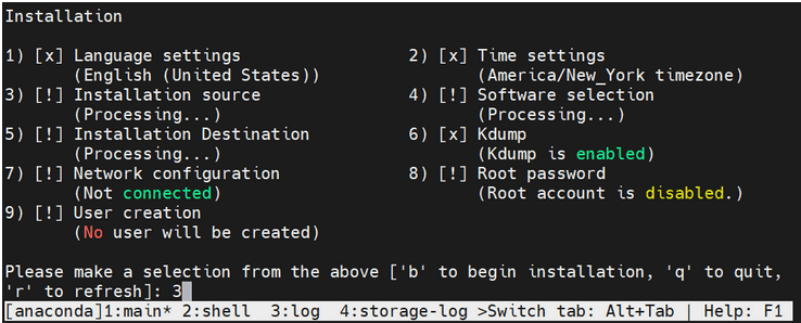
- Select a source type from the following installation sources:
- CD/DVD
- Local ISO file
- Network
Figure 5-3 Installation Source

- Select a device containing the ISO file. After selection of ISO file,
the installation process initiates.
Figure 5-4 ISO File

- Wait for the processing to complete. Press "r" to
refresh and check if step 3 is completed before proceeding to step 4.
Figure 5-5 Installation process
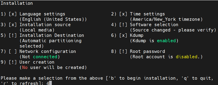
- Select a software from the following base environment.
- Server with GUI
- Server
- Minimal Install
- Workstation
- Custom Operating System
- Virtualization Host
Figure 5-6 Software Selection

- Select Additional Software for the selected
environment:
Figure 5-7 Additional Software
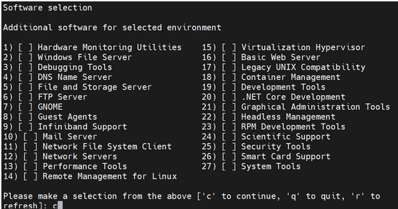
- Wait a moment for the processing to complete, then press "r" to refresh and confirm that step 4 is marked as complete.
Figure 5-8 Installation
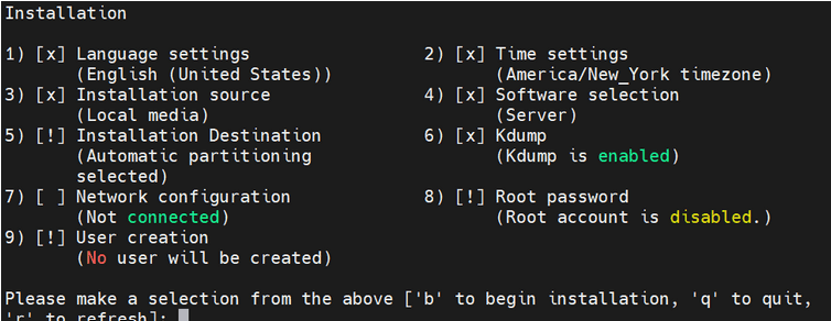
- Proceed with the next steps, and once all the steps are marked with
[x], press "b" to start the installation.
Figure 5-9 Installation
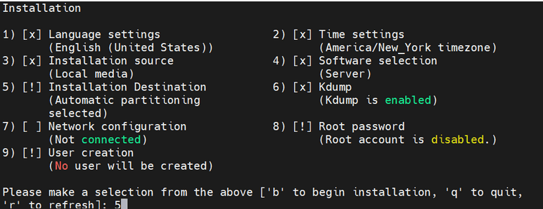
Installation Destination is selected during the probing storage.
Figure 5-10 Probing storage

- For partitioning options, select the space to be used for the install
target or manually assign mount points.
Figure 5-11 Partitioning Options

- Select a Partition Scheme Configuration from the following options:
- Standard Partition
- LVM
- LVM Thin Provisioning
Figure 5-12 Partitioning Scheme Options

- Set a strong password for the root user and confirm.
Figure 5-13 Set password for root user

After selection of the password, the installation procedure initiates.
Figure 5-14 Begin Installation
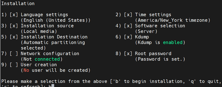
Writing network configuration in progress.
Figure 5-15 Writing network configuration
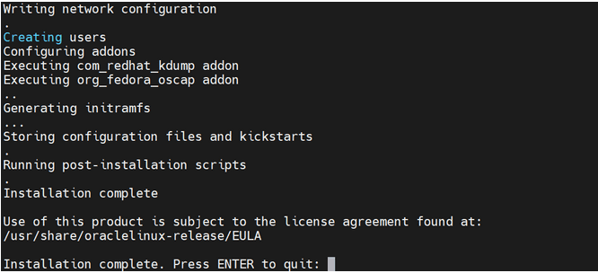
- Press Enter Key to quit.
- User must add 3 network interfaces for each VM, xmi, imi, and xsi. Shut
down the VM and follow the following steps if you encounter a "No PCI
slots available" error while adding any interface.
Note:
This step is optional, user must add controller only if they encounter "No PCI slots available"error while adding an interface. - Run the following command to add the
controller:
virsh edit <vm-name> and add below controller after index=7 <controller type='pci' index='8' model='pcie-root-port'> <model name='pcie-root-port'/> <target chassis='8' port='0xf'/> <address type='pci' domain='0x0000' bus='0x00' slot='0x01' function='0x7'/> </controller> - Turn on the VM after controller is added.
- Log in to the host machine with a valid username and password.
Figure 5-16 Login Page
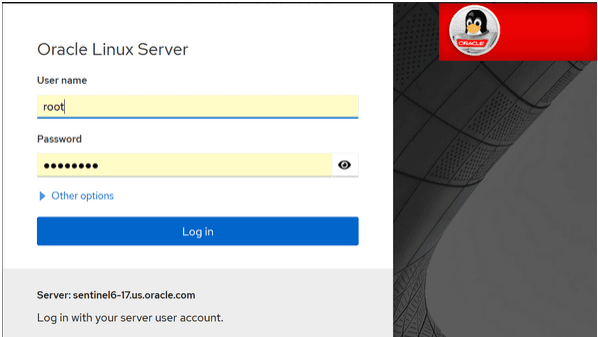
After signing in, the system will automatically open the Overview page.
Figure 5-17 Overview

- Click Virtual machines and search for the
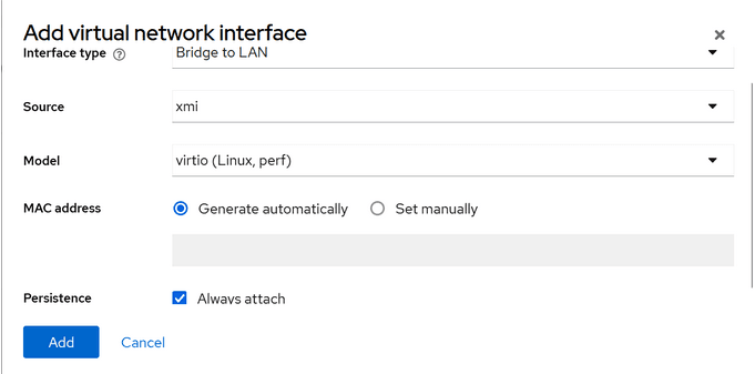
idih-mysqlVM. Go to Network interfaces section, click Add Network Interface, select value as shown in the following screenshot, and click Add.Figure 5-18 Add Virtual Network Interface
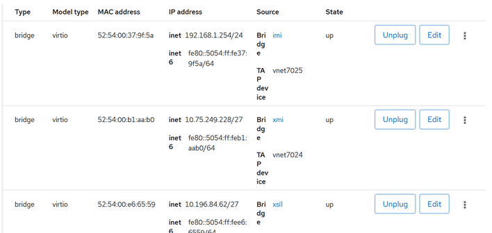
- Apply the same process to the IMI and XSI interfaces. The following
screenshot displays all the interfaces.
Figure 5-19 Interfaces
- Log in to the VM through CLI. You can change the hostname of the VM by
editing the following command. Provide a name of your
preference.
- vi /etc/hostname - Assign a valid IP address for all the three interfaces for the three VMs created.
- Run
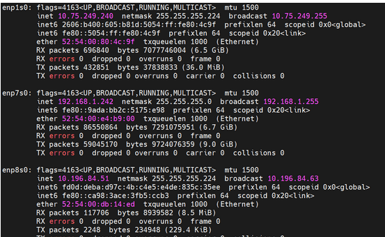
ifconfigcommand and take a note of device names -enp1s0, enp7s0, and enp8s0. Here, enp1s0 represents xmi, enp7s0 represents imi, and enp8s0 represents xsi. - Run the following command, it will display the status as "disconnected"
for all the interfaces.
nmcli dev status - To assign an IP addresss to enp1s0, run the following
command:
If you get an error, then most likely the device is not up. You can bring it up by running the following command:nmcli con edit enp1s0
.nmcli dev up enp1s0 - After the device is up, re-run the following command. Prompt must be
visible as shown in the below screenshot:
nmcli con edit enp1s0. nmcliFigure 5-20 Prompt

- Perform the following steps to assign the IP address to
enp1s0:- Set ipv4.addresses <ip-address>
- set ipv4.gateway <gateway-ip>
- Save and quit.
- You can type print in
nmcliprompt to verify the assigned IP. - Apply the same steps for enp7s0 and enp8s0 interfaces.
- Perform the following steps to assign the IP address to
- Ensure that
onboot=yesin the following/etc/sysconfig/network-scripts/ifcfg-enp1s0ile. - Run the following command to check the local time zone.
If it's not GMT, change it to GMT by running the following commandtimedatectltimedatectl set-timezone - Restart the VM and check if IP addresses are assigned with help of
ifconfigcommand. Also, verify that local time zone is now set to GMT by running the following command:
.timedatectlFigure 5-21 Local Time Verification
- Repeat steps 8 to 13 for IDIH Kafka and IDIH Service VMs.
- Ensure that you are able to reach the IMI IPs of Mysql VM and Kafka VM from Service VM.
Installation Package Download and Extraction
The installation TAR file can be downloaded on any of the three VMs. After downloaded, extract (untar) the TAR file.
Directory Structure
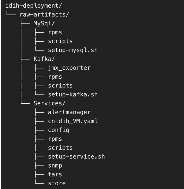
After extraction, the directory structure will appear as follows:
Figure 5-22 Directory Structure
Deployment of Components Across VMs
Distribute the extracted directories to their respective VMs as follows:
- Copy the MySql directory to the MySQL VM at any preferred location.
- Copy the Kafka directory to the Kafka VM at any preferred location.
- Copy the Services directory to the Services VM at any preferred location.
MySQL Setup
Perform the following steps to set up MySQL on the MySQL VM:
- Access the MySQL VM:
- Log in to MySQL VM.
- Navigate to the path where MySql directory was copied.
- Run the MySQL Setup Script:
- Move inside the MySql directory.
- Locate the
setup-mysql.shscript.Note:
Ensure the linesudo restorecon -v/etc/my.cnfis commented out if it appears in the script. - Run the script using the following command:
./setup-mysql.sh
- Configuration During Execution:
- The script will prompt for an IP address to be configured as the MySQL bind address.
- Enter the IMI IP of the MySQL VM when prompted.
- Completion: After the script is complete, MySQL will be successfully set up on the VM.
- Post installation steps:
- Connect to the MySQL through SSH.
- Run the following
command:
sudo restorecon -v /etc/my.cnf - To create the swap file run the following
commands:
sudo fallocate -l 12G /swapfile sudo chmod 600 /swapfile sudo mkswap /swapfile sudo swapon /swapfile echo '/swapfile swap swap defaults 0 0' | sudo tee -a /etc/fstab - To edit the mysqld service file run the following
command:
systemctl edit mysqld - paste the below content and save
it,
[Service]
MemoryMax=11G
[mysqld]
default_time_zone = 'GMT'
- To restart the MySQL service, run the following
command:
systemctl restart mysqld
Kafka Setup
Perform the following stepsto set up Kafka on the Kafka VM:
- Access the Kafka VM:
- Log in to Kafka VM.
- Navigate to the path where Kafka directory was copied.
- Run the Kafka Setup Script:
- Move inside the Kafka directory.
- Locate the
setup-kafka.shscript. - Run the script using the following
command:
./setup-kafka.sh
- Configuration During Execution
- The script will prompt for the Kafka IMI IP.
- Enter the IMI IP of the Kafka VM when prompted.
- The script will then prompt for the Kafka XSI IP.
- Enter the XSI IP of the Kafka VM.
- Kafka and Kraft services will be initiated on the specified IPs.
- The script will prompt for the Kafka IMI IP.
- Completion: After the successful health check is completed, Kafka will be fully set up on the VM.
- This is an optional step. Follow the instructions in this step only if you need to
use Kafka XMI IP instead of the default Kafka IMI IP for communication with DSR.
- Uncomment advertised.listeners=INTERNAL_PLAINTEXT://192.168.1.237:9092,INTERNAL_SSL://192.168.1.237:9093,EXTERNAL://[kafka_xmi]:9094 line in broker.properties file(path: /opt/kafka/config) and replace [kafka_xmi] with Kafka XMI IP.
- Comment advertised.listeners=INTERNAL_PLAINTEXT://192.168.1.237:9092,INTERNAL_SSL://192.168.1.237:9093, EXTERNAL://10.196.84.46:9094 line.
- Run the below commands to restart Kraft and Kafka
services:
systemctl restart kraft-controller
systemctl restart kafka
Service Setup
Perform the following steps to set up the services on the Service VM:
- Access the Service VM:
- Log in to the Service VM.
- Navigate to the directory where
setup-service.shscript is located.
- Move the store Directory
- Before running the setup script, move the store directory to the
/opt/path using the following command:mv store /opt/
- Before running the setup script, move the store directory to the
- Run the Service Setup Script:
- Run the script using the below
command:
./setup-service.sh
- Run the script using the below
command:
- Perform the following configuration during execution:
- The script will prompt for several inputs during
execution:
- Service IMI IP: Enter the IMI IP of the Service VM.
- Service XMI IP: Enter the XMI IP of the Service VM.
- Kafka IMI IP: Enter the IMI IP of the Kafka VM (configured in previous steps).
- MySQL IMI IP: Enter the IMI IP of the MySQL VM (configured in previous steps).
- After these inputs are provided, the script will start the
required services and proceed with the health check.
You can ignore the following error as this will be addressed in next section:
[ERROR] <timestamp> - Reached retry limit. Aborting
- The script will prompt for several inputs during
execution:
- Perform the following procedure post installation and UI access:
- Run podman
ps -a. You will notice thatnfconfigservice would have exited. - Log in to service VM and open
cnidih_VM.yamlfile. - <Replace with SOAM VIP> must be replaced with a valid active SOAM IP. Save and exit.
- Navigate to Protrace section and enable the following
property
NFCONFIG_CLIENT_ENABLEDto true. - Run the following
commands:
podman rm -f --alldocker-compose -f cnidih_VM.yaml up -d - Verify that all services are up and running using the
following command
podman ps -a. - After all services are running, you can access the UI at: https://<SERVICE XMI IP>.
Completion
This completes the setup for MySQL, Kafka, and Services. The deployment is now ready for use.
- Run podman