5.5.4 IDIH Deployment on Oracle Cloud Infrastructure (OCI) with RAW Images
Perform the following procedure for IDIH Deployment on OCI with RAW Images:
- Login to OCI with valid credentials.
- Navigate to Compute, Instances, and click Create Instance.
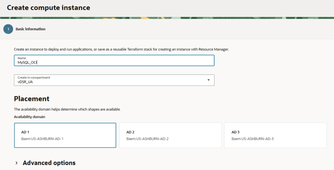
- Provide an instance name for MySQL VM. Example: MySQL_OCI.
Figure 5-28 Create Compute instance
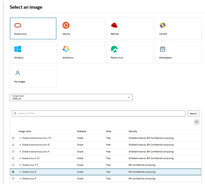
- Click Change Image, select Oracle
Linux 8, and click Select Image.
Figure 5-29 Select an Image
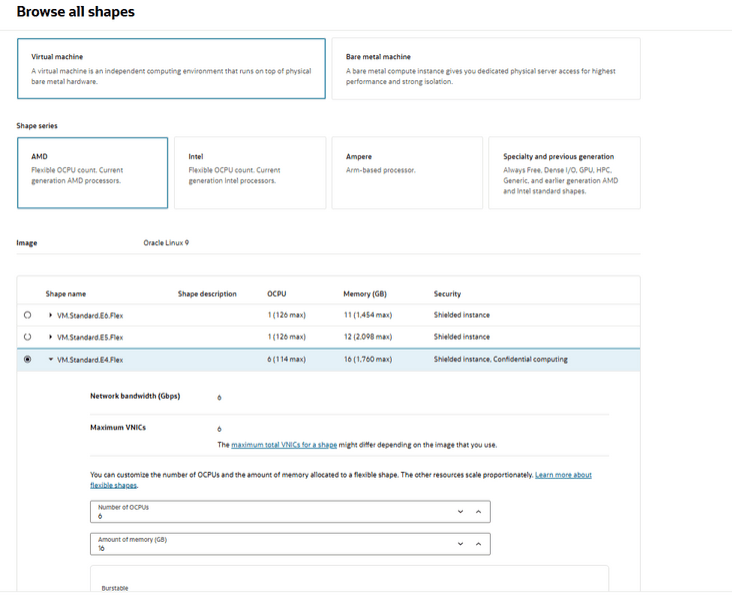
- Click Change Shape, select an appropriate shape
based on the requirements and availability in the OCI compartment. Adjust the number
of OCPU such as the number of vCPUs remains 6. Memory size is 16 GB. Click
Select Shape and click Next.
Figure 5-30 Browse all Shapes
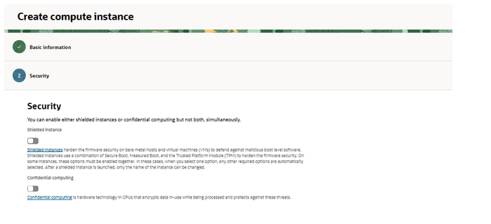
- No changes are required in Security. Click
Next.
Figure 5-31 Create Compute Instance
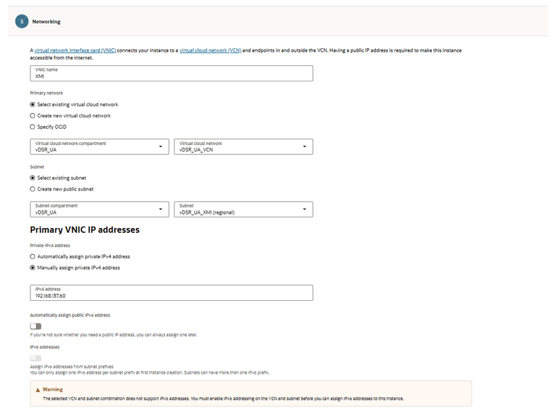
- In the Networking, define the XMI VNIC name,
VCN, and XMI subnet. Manually assign an IPv4 address.
Figure 5-32 Networking
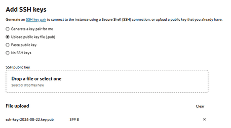
- In Add SSH keys, select own key or generate a
new one. Click Next.
Figure 5-33 SSH Keys
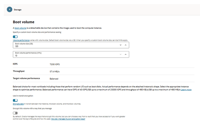
- In the Storage section, specify a custom boot
volume size for the VM and click Next.
Table 5-14 VM values
VM Boot Volume Size GB MySQL 220 Kafka 170 GB Services 120 Figure 5-34 Boot Volume
- Review the configuration, if correct, click Create.
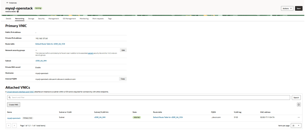
- After the VM is created and running, navigate to
Networking and click Create VNIC.
Figure 5-35 mysql-OpenStack
- Provide a name for the IMI VNIC, select the IMI subnet, manually assign
an IP, and click Submit, repeat step 10 for XSI1 VNIC.
Figure 5-36 Attached VNICs

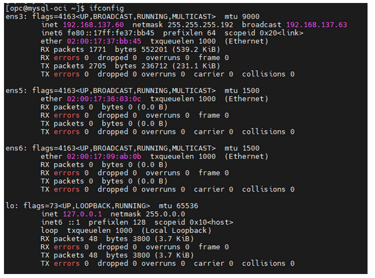
- SSH into the MySQL VM using the XMI interface. Use the assigned IP and
SSH key. The only interface with an IP assigned is ens3.
Figure 5-37 ifconfig
- Network scripts
- Configure ens5 and ens6 by navigating
to:
"cd /etc/sysconfig/network-scripts/"and"ll"Figure 5-38 Network Scripts

- Run the following commands as root to configure the interfaces:
- Configure the IMI interface:
Figure 5-39 Ethernet
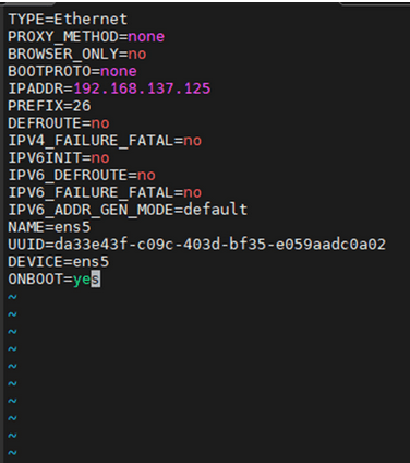
- Save and close.
- Configure the XSI1 interface
Figure 5-40 XSI Interface
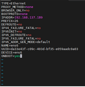
- Run the following command to restart the
VM:
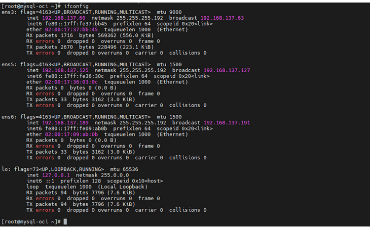
[]# sudo init 6 - Verify Network Interfaces: After the restart, verify if ens3,
ens5, and ens6 interfaces consist IP address by running the following
command:
[]# ifconfigEnsure the interfaces are up and running. Perform steps 1 to 22 for Kafka and Service VMs as well.
Figure 5-41 ifconfig
- Configure ens5 and ens6 by navigating
to:
- After creating 3 VMs, ensure you can reach between all 3 VMs using their IMI IPs.
- Firewall Configuration (All 3 VMs):
- Run the following command to check firewall
status:
sudo systemctl status firewalldNote:
Firewall must be disabled in Services VM. - Run the following command if the firewall is not running, start and enable
it:
sudo systemctl start firewalld sudo systemctl enable firewalld - Verify the firewall is
running:
sudo systemctl status firewalld - DNS configuration
- Ensure the file
/etc/resolv.conffile consists the required DNS configuration. - Verify that the ash proxy
proxy=http://www-proxy-ash7.us.oracle.com:80is not present. Use the following configuration:[main] gpgcheck=1 installonly_limit=3 clean_requirements_on_remove=True best=True proxy=http://www-proxy.us.oracle.com:80 retries=100 - Unset proxies and run below commands to install tar and
dos2unix
utilities:
sudo dnf install tar
sudo dnf install dos2unix
- Ensure the file
- Run the following command to check firewall
status:
- Installation Package Download and Extraction: The installation TAR file can be downloaded on any of the three VMs. Extract (untar) the TAR file once downloaded.
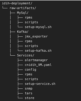
- Directory Structure: After extraction, the directory structure will
appear as follows:
Figure 5-42 Directory Structure
- Deployment of Components Across VMs
- Distribute the extracted directories to their respective VMs:
- Copy the MySql directory to the MySQL VM at any preferred location.
- Copy the Kafka directory to the Kafka VM at any preferred location.
- Copy the Services directory to the Services VM at any preferred location.
- Distribute the extracted directories to their respective VMs:
- MySQL Setup
- Access the MySQL VM:
- Log in and navigate to the MySQL directory.
- Run the MySQL Setup Script
- Locate
setup-mysql.sh. - Run the below command to run the script:
./setup-mysql.sh
- Locate
- Configuration During Execution: Enter the IMI IP of the
MySQL VM when prompted for the MySQL bind address.
Completion: After the script is complete, MySQL will be successfully set up on the VM.
- Access the MySQL VM:
- Kafka Setup
- Access the Kafka VM: Log in and navigate to the Kafka directory.
- Run the Kafka Setup Script
- Locate the setup-kafka.sh script
- Run the below command for the
script:
./setup-kafka.sh
- Configuration during execution
- When prompted, enter the Kafka IMI IP and Kafka XSI IP. when prompted by the script.
- Kafka and Kraft services will be initiated on the specified IPs.
After the successful health check is completed, Kafka will be successfully set up on VM.
- Optional step, only if you need to use Kafka XMI IP instead of
the default Kafka IMI IP for communication with DSR.
- Uncomment:
advertised.listeners=INTERNAL_PLAINTEXT://192.168.1.237:9092,INTERNAL_SSL://192.168.1.237:9093,EXTERNAL://[kafka_xmi]:9094 line in broker.properties file(path: /opt/kafka/config) and replace[kafka_xmi] with Kafka XMI IP - Comment:
advertised.listeners=INTERNAL_PLAINTEXT://192.168.1.237:9092,INTERNAL_SSL://192.168.1.237:9093, EXTERNAL://10.196.84.46:9094 line.
- Uncomment:
- Run the below commands to restart Kraft and Kafka
services:
systemctl restart kafkaAfter successful execution of the health check, Kafka is successfully set up on VM.
- Service Setup
- Access the Service VM
- Navigate to the directory where the
setup-service.shscript is located. - Move the store Directory to the
/opt/path using the following command:mv store /opt/ - Edit the Docker-compose file:
- Navigate to the
Services/
                                directory
. - Edit
cnidih_VM.yamlfile:- <REPLACE WITH SOAM VIP> must be replaced with a valid active SOAM IP.
- Navigate to Protrace section and enable the
following property
NFCONFIG_CLIENT_ENABLEDto True. - Save and exit.
- Run the following command for the Service Setup
Script:
./setup-service.sh
- Navigate to the
- Configuration during execution: The script will prompt for
several inputs during execution:
- Enter Service IMI IP, Service XMI IP, Kafka IMI IP, and
MySQL IMI IP.
Note:
For IPv6 setups, the above IPs must be entered in square brackets ( [] ).After these inputs are provided, the script will start the required services and proceed with the health check.
- Run the following command to verify if all services are
running:
podman ps -aAccess the UI at:
https://<SERVICE XMI
                                        IP>/#/
.
This completes the setup for MySQL, Kafka, and Services. The deployment is now ready for use.
- Enter Service IMI IP, Service XMI IP, Kafka IMI IP, and
MySQL IMI IP.