1.5 Oracle Exalytics In-Memory Machine Description
This section shows the connectors and buttons on the front and back panels of the Oracle Exalytics In-Memory Machine.
It contains the following topics:
Parent topic: Getting Started
1.5.1 Front Panel Features
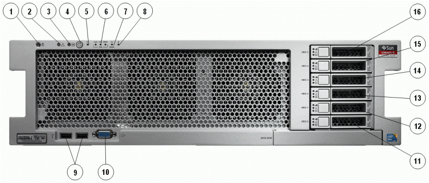
Figure 1-1 shows the front panel of the Oracle Exalytics In-Memory Machine.
Figure 1-1 Oracle Exalytics In-Memory Machine Front Panel

Description of "Figure 1-1 Oracle Exalytics In-Memory Machine Front Panel"
Table 1-2 describes the front panel buttons and LED indicators.
Table 1-2 Figure Legend
| Number | Description |
|---|---|
|
1 |
Locator LED/Locator button: white |
|
2 |
Service Action Required LED: amber |
|
3 |
Main Power/OK LED: green |
|
4 |
Power button |
|
5 |
SP OK/Fault LED: green/amber |
|
6 |
Service Action Required LEDs (3) for Fan Module (FAN), Processor (CPU) and Memory: amber |
|
7 |
Power Supply (PS) Fault (Service Action Required) LED: amber |
|
8 |
Over Temperature Warning LED: amber |
|
9 |
USB 2.0 connectors (2) |
|
10 |
DB-15 video connector |
|
11 |
Hard disk drive 0 |
|
12 |
Hard disk drive 1 |
|
13 |
Hard disk drive 2 |
|
14 |
Hard disk drive 3 |
|
15 |
Hard disk drive 4 |
|
16 |
Hard disk drive 5 |
Parent topic: Oracle Exalytics In-Memory Machine Description
1.5.2 Back Panel Features
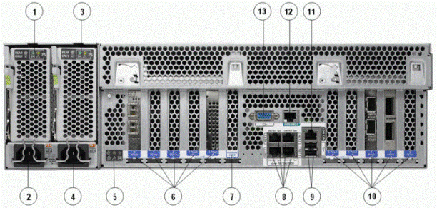
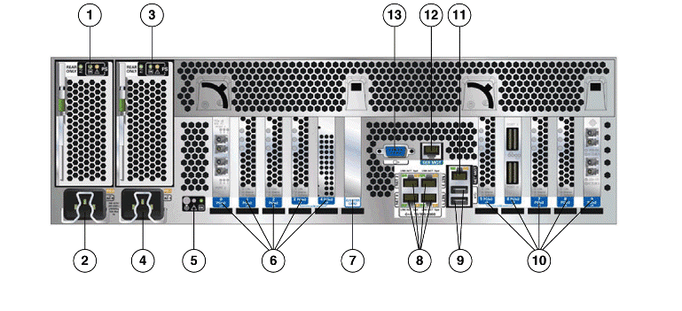
Figure 1-2 and Figure 1-3 shows the back panel of the Oracle Exalytics In-Memory Machine X2-4, and Oracle Exalytics In-Memory Machine X3-4, respectively.
Figure 1-2 Oracle Exalytics In-Memory Machine X2-4 Back Panel

Description of "Figure 1-2 Oracle Exalytics In-Memory Machine X2-4 Back Panel"
Figure 1-3 Oracle Exalytics In-Memory Machine X3-4 Back Panel

Description of "Figure 1-3 Oracle Exalytics In-Memory Machine X3-4 Back Panel"
Table 1-3 describes the back panel buttons and LED indicators.
Table 1-3 Figure Legend
| Number | Description |
|---|---|
|
1 |
Power supply unit 0 status indicator LEDs: Service Action Required: amber DC OK: green AC OK: green or amber |
|
2 |
Power supply unit 0 AC inlet |
|
3 |
Power supply unit 1 status indicator LEDs: Service Action Required: amber DC OK: green AC OK: green or amber |
|
4 |
Power supply unit 1 AC inlet |
|
5 |
System status LEDs: Power/OK: green Attention: amber Locate: white |
|
6 |
PCIe card slots 0–4 |
|
7 |
Cluster card slot |
|
8 |
Network (NET) 10/100/1000 ports: NET0–NET3 |
|
9 |
USB 2.0 connectors (2) |
|
10 |
PCIe card slots 5–9 |
|
11 |
Service processor (SP) network management ( |
|
12 |
Serial management ( |
|
13 |
DB-15 video connector |
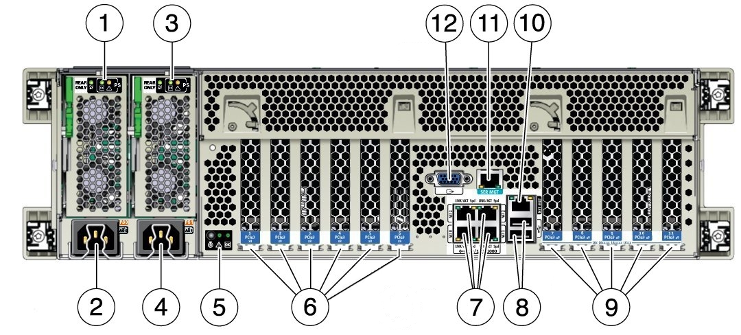
Figure 1-4 Oracle Exalytics In-Memory Machine X6-4, X5-4, and X4-4 Back Panel

Description of "Figure 1-4 Oracle Exalytics In-Memory Machine X6-4, X5-4, and X4-4 Back Panel"
Table 1-3 describes the back panel buttons and LED indicators on the Oracle Exalytics In-Memory Machine X6-4, X5-4, and X4-4 Back Panel.
Table 1-4 Figure Legend for Oracle Exalytics In-Memory Machine X6-4, X5-4, and X4-4 Back Panel
| Number | Description |
|---|---|
|
1 |
Power supply unit 0 status indicator LEDs: Service Action Required: amber DC OK: green AC OK: green or amber |
|
2 |
Power supply unit 0 AC inlet |
|
3 |
Power supply unit 1 status indicator LEDs: Service Action Required: amber DC OK: green AC OK: green or amber |
|
4 |
Power supply unit 1 AC inlet |
|
5 |
System status LEDs: Power/OK: green Attention: amber Locate: white |
|
6 |
PCIe card slots 1–6 |
|
7 |
Network (NET) 10/100/1000 ports: NET0–NET3 |
|
8 |
USB 2.0 connectors (2) |
|
9 |
PCIe card slots 7–11 |
|
10 |
Service processor (SP) network management ( |
|
11 |
Serial management ( |
|
12 |
DB-15 video connector |
Parent topic: Oracle Exalytics In-Memory Machine Description