Importing Sensor Devices Data
Overview of Importing Sensor Devices Data
The two types of sensor data collected from shop floor devices are:
-
Stream Data
-
Alert/Event Data
Stream Data includes values for parameters such as temperature, pressure, vibration, cutting speed, spindle RPM, and so on.
Alert/Event Data includes the following alert type information:
-
Machine Status, such as up, down, idle, or in-use.
-
Job Status, such as started, paused, resumed or completed.
-
Pattern Match.
-
Threshold Violations.
-
Door State, such as open or closed.
-
Power State, such as up or down.
You can use specific templates provided by the application to capture stream data and alert data which you can then upload for data contextualization.
Oracle partners can help users to configure machine data acquisition systems, such as Supervisory Control and Data Acquisition (SCADA), Distributed Control Systems (DCS) and other gateway device systems, to extract machine sensor data in the CSV file format. Users can then upload these sensor data files into Oracle Adaptive Intelligent Apps for Manufacturing in batch mode. The application processes the sensor stream data and alert data, contextualizes this data with equipment and work order information, and then summarizes the contextualized data for analysis.
Sensor Devices Data Import Steps
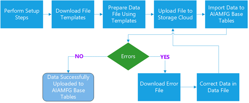
-
Define setups. For example: define sensor device mappings.
-
Download the sensor devices data file template, either for alert or stream data.
-
Prepare or enter the data into the CSV file following the template guidelines.
-
Submit the file for upload to Oracle Storage Cloud Service.
-
Run the data import program to import data into the target base tables.
-
If errors occur, download the error file, correct the data, remove the error message columns, save the error file as a new CSV file, and then upload the file again.
-
After a successful import, the summarized data/features are imported into the AIAMFG base tables.
Additional Information: Alternatively, you can perform steps 4 - 7 using REST web services, which are provided with Oracle Adaptive Intelligent Applications for Manufacturing, instead of the user interface. See: Uploading Sensor Device CSV Files Using REST Web Services
In addition to completing the setup steps described in Setting Up Data Ingestion, you must also create and map sensor devices.
To map sensor devices using the user interface see: Setting Up Sensor Device Data Mappings.
To import mappings using spreadsheet templates see: Uploading CSV Files Using the Sensor Devices Data User Interface.
Setting Up Sensor Devices Mappings
Before acquiring sensor data, you must define the sensor devices in the application. Skip this step if the sensor device mapping is already defined for the sensor devices in the application.
Define sensor devices by entering the sensor device IDs and sensor attributes, such as manufacturer, model number, and serial number. Next, map the sensor devices to the ERP equipment and equipment instance.
The data collected from the sensor devices is contextualized with the Enterprise Resource Planning (ERP) data. You can set the contextualization rules and priority for equipment and work context (and serial context for discrete serialized manufacturing organizations). You can also enter stream parameter names derived from IoT systems and select the corresponding equipment parameters from ERP systems for process manufacturing organizations, or enter equipment parameters for discrete manufacturing organizations along with the parameter units of measure. The pages in the application display the equipment parameter names.
When you map a sensor device, you can select a time series feature set you have defined for either production analysis usage or machine event analysis usage. When the data set request runs, the program extracts features from the time series data based on the feature set selected for production analysis usage. You can also use the sample interval for processing event data. You can enter the stream sample interval value or leave the field blank, allowing the application to derive the sample interval from the sensor data. The time series data is split using the stream sample interval and event identification processing is applied based on the feature set selected for machine event analysis usage.
Oracle Adaptive Intelligent Apps for Manufacturing provides a user interface to map sensor devices, as well as specific templates for capturing stream data and alert data, to which you can then add sensor data information and then upload the files.
Creating and Mapping Sensor Device Data
Use the Setup tab in the Sensor Devices page to:
-
View existing sensor device mappings.
-
Create a new sensor device mapping.
-
Update an existing sensor device mapping.
-
Duplicate an existing sensor device mapping.
-
Download the Sensor Device mapping template.
-
Import sensor device mapping definitions using CSV files.
-
Export existing sensor device mappings in CSV files.
To view a sensor device mapping
-
Navigate to the Sensor Devices page.
From the Home Page, click Insights or Predictions, then click the Configuration link, and then Sensor Devices. Alternatively, from the Home page, click Setup and then Sensor Devices.
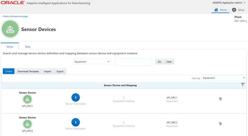
-
Use the Setup tab in the Sensor Devices page to view details such as the sensor device name and the number of sensor parameters for process manufacturing or discrete manufacturing, depending on the organization selected. You can search for and view sensor device definitions and mappings using the following criteria:
-
Equipment
-
Equipment Instance
-
Sensor Device ID
-
Equipment Parameter
Select a search criteria and click Go.
-
-
From the Sensor Device and Mapping table, select a sensor device mapping and click Sensor Parameters to view names of stream parameters and the equipment parameter names mapped to them.
For process manufacturing organizations you can view equipment instance and equipment.

For discrete manufacturing organizations you can view equipment instance, equipment and department.

To create a sensor device mapping
-
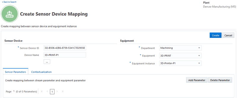
Navigate to the Create Sensor Device Mapping page.
Use the Setup tab in the Sensor Devices page to create a sensor mapping.
Click Create.
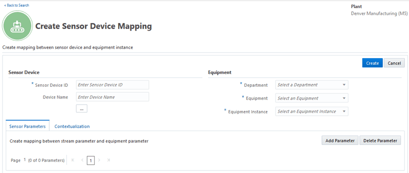
Map Sensor Device ID
-
In the Create Sensor Device Mapping page, enter values in the following fields:
-
Sensor Device ID
-
Device Name
-
-
Click the ellipsis points (...) under Sensor Device.
Enter information for the following Sensor Device Attributes fields:
-
Manufacturer
-
Model Number
-
Serial Number
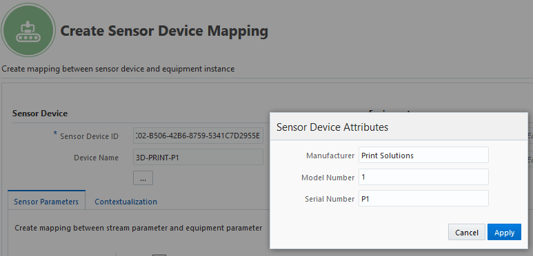
-
-
Map the sensor device you have entered to its ERP equipment and equipment instance:
For process manufacturing organizations:
Select Equipment and Equipment Instance.

Note: For process manufacturing users, all the equipment parameters have to be defined in ERP before setting up the parameter mapping.
For discrete manufacturing organizations:
Select Department, Equipment, and Equipment Instance.

Note that you can update the mapping of a sensor device to the equipment and equipment instance, till you upload and process sensor data for the mapped sensor device. You cannot update the mapping once you have uploaded and processed sensor data for a mapped sensor device.
Process Stream Data
-
Use the Sensor Parameters tab to create mappings between a stream parameter and the equipment parameter. You can map multiple parameters with the sensor device.
Note: Not all sensor devices will send sensor stream data. In case of sensors that only send alert data, there is no requirement to map parameters.
-
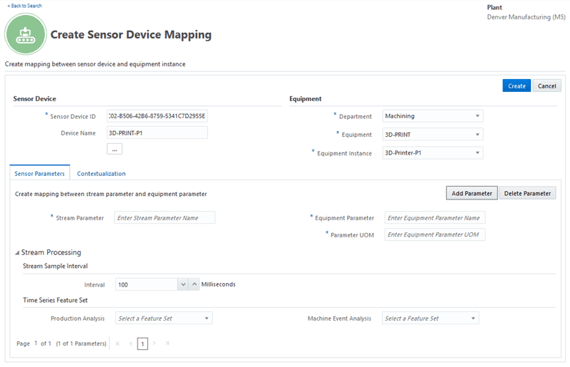
Click Add Parameter to add stream parameters you will map to the equipment parameters in the ERP.
-
Enter the Stream Parameter.
-
In the Equipment Parameter field specify the equipment parameter in the ERP.
For process manufacturing organizations:
Select the Equipment Parameter from the list of values. The parameter UOM is displayed depending on equipment parameter you select.

For discrete manufacturing organizations:
Enter the Equipment Parameter and the Parameter UOM.

Note that you can add new stream parameters and update an existing stream parameter in the sensor device mapping. When you use the sensor device mapping template to import additional parameters, you can either add new parameters or update existing stream parameters.
-
Click Delete Parameter to delete a parameter.
Process Event Identification
-
The stream sample interval is used when a time series feature set has been selected in the Machine Event Analysis field. The actual sample interval is derived from sensor data for event detection. Optionally, you can enter a value.
In Stream Sample Interval, use the Interval field to:
-
Allow the sample interval value to be derived from the sensor data by the application automatically and generate events based on the actual interval value.
-
Enter the same frequency at which the machine sensor sends the data in milliseconds. If you enter a value, events are generated based on the sample interval value you have entered, even if the actual interval is different.

The Interval field is used to ensure that sensor stream data is streaming correctly and to calculate and generate events based on the intervals from the sensor data.
For example, if a parameter is set to stream at an interval of 100 milliseconds, and in case there is a gap in the data set readings, the machine will gauge this gap and split the data for processing event identifications.
See: Processing Event Identification and Summarization
-
-
In the Time Series Feature Set region, select a feature set in the Machine Event Analysis field. Alert messages are usually received directly from the sensors, but machine alerts can also be indirectly derived from a time series sensor stream data. When a time series features set is selected in this field, it enables event identification based on the time series feature set.

See: Setting Up Times Series Features Sets, Oracle Adaptive Intelligent Apps for Manufacturing User's Guide
-
In the Time Series Feature Set region select a feature set in the Production Analysis field. When a time series features set is selected in this field, based on the definition of the time series features set, it will generate features that will be used in model building and analysis.

See: Setting Up Time Series Features Sets, Oracle Adaptive Intelligent Apps for Manufacturing User's Guide
-
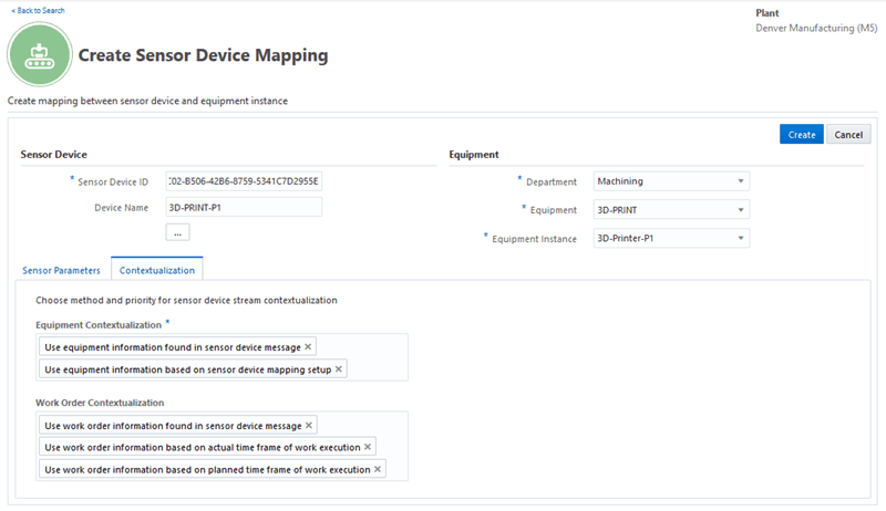
Select the Contextualization tab to select a priority sequence of the context source for both equipment and work order contextualization.
See: Processing Data Contextualization
-
Equipment Contextualization
In the mandatory Equipment Contextualization, select the priority sequence of the context source. You can select to:
-
Use equipment information found in sensor device message
-
Use equipment information found in sensor device mapping setup
You must select at least one of the options in this field.
The default first option for the priority sequence is using equipment information found in sensor device message and the second is using equipment information found in sensor device mapping setup. For example, if the first default option is selected, this ensures that the context values from the sensor device is first sourced.
If the context information from the first option is not available and not valid, the context value from the sensor machine will be sourced from the second priority option which is essentially the mapping you created between the sensor device and the equipment instance.
-
-
Work Order Contextualization
Optionally, in Work Order Contextualization, select the priority sequence of the context source. You can select to:
-
Use work order information found in sensor device message
-
Use work order information based on actual time frame of work execution
-
Use work order information based on planned time frame of work execution
Note: You can disable the work order contextualization for sensor records for an equipment by removing all the three values. In this case, the contextualization is completed without work order/ serial context.
The default first option for the priority sequence is Use work order information found in sensor device message, followed by Use work order information based on actual time frame of work execution as the second option, and Use work order information based on planned time frame of work execution as the third option. You can choose to have only one of the above, or a combination of two of the options.
For example, if the first option is selected as Use work order information found in sensor device message, the context values from the sensor machine is first sourced from the sensor message.
If context values from the first option is not available and not valid, the context value from the sensor machine is sourced from the second priority option which is Use work order information based on actual time frame of work execution. If valid context information cannot be derived from the sensor device tag, or from actuals, the context values is derived from the third option which is Use work order information based on planned time frame of work execution.
Note: You cannot prioritize to use work order information based on planned time frame of work execution before work order information based on actual time frame of work execution. You can however select to use work order information based on planned time frame of work execution as the only source for context values.
-
-
Click Create to complete the sensor device mapping.
To update a sensor device mapping
-
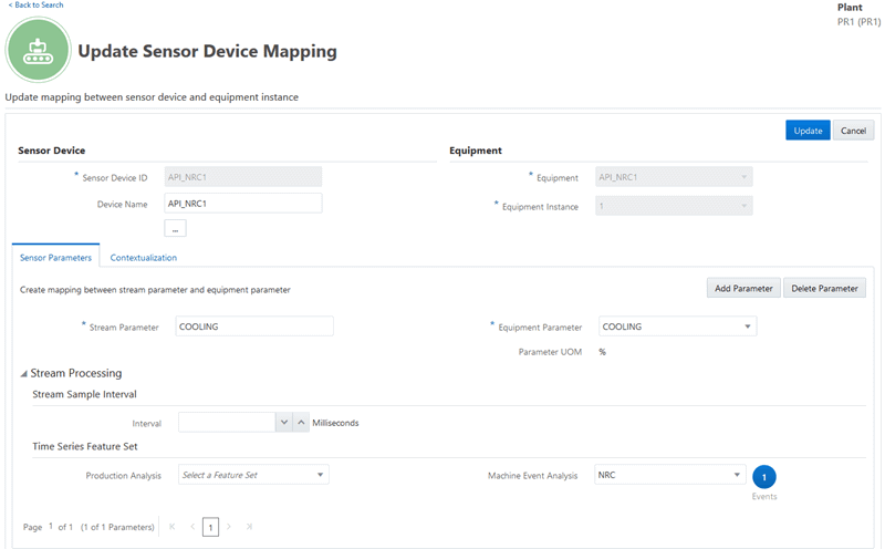
Select the existing sensor device mapping you would like to update. From the Actions link, click Update Sensor Device Mapping.
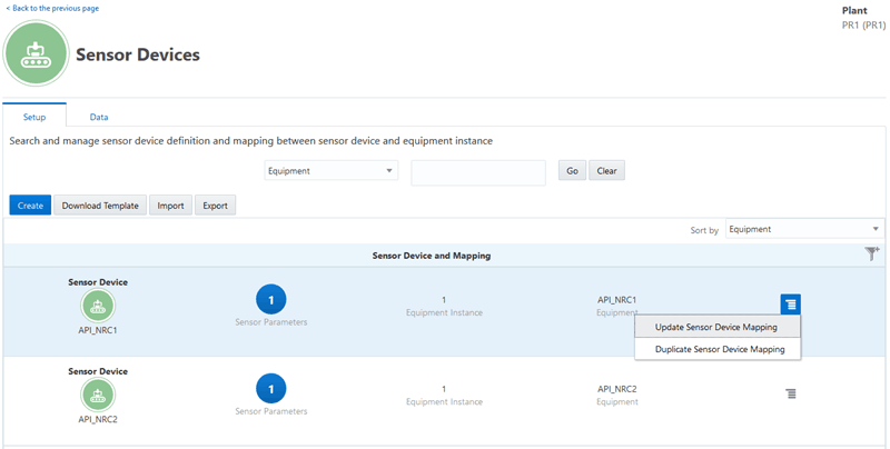
The Update Sensor Device Mapping page appears.
-
Note that you cannot update the Sensor Device ID, Equipment and Equipment Instance fields for process organizations, and Sensor Device ID, Department, Equipment and Equipment Instance fields for discrete manufacturing organizations, once you have uploaded and processed sensor data for a mapped sensor device.
You can update the following:
-
Device Name.
-
Sensor Device Attributes.
-
Stream Parameter.
-
Equipment Parameter.
-
Stream Sample Interval information.
-
Time Series Feature Sets Information.
-
Contexualization information
-
-
Click Update to save and update the sensor device mapping.
To duplicate a sensor device mapping
-
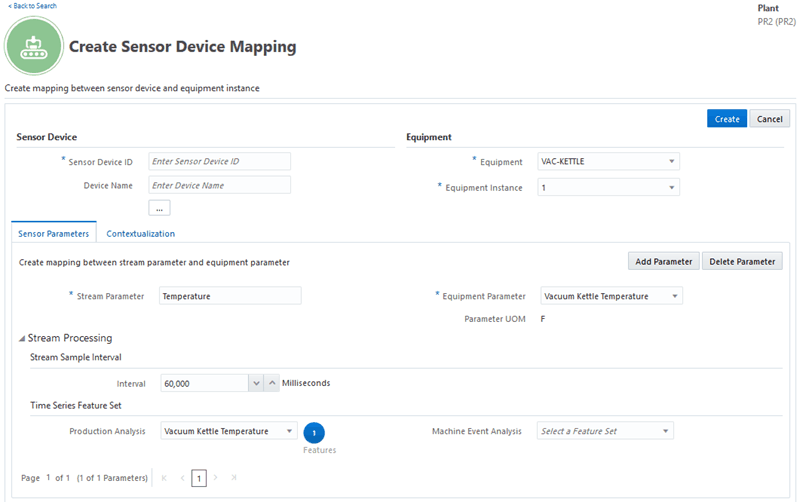
Select the existing sensor device mapping you would like to duplicate. From the Actions link, click Duplicate Sensor Device Mapping. The Create Sensor Device Mapping page appears.
-
Enter information for:
-
Sensor Device ID
-
Device Name
-
-
Note that the following information is duplicated from the existing sensor device mapping your selected:
-
Equipment.
-
Equipment Instance
-
Department (for discrete manufacturing organizations).
-
Stream Parameter.
-
Equipment Parameter.
-
Stream Sample Interval information.
-
Time Series Feature Sets Information.
-
Contexualization information
You can choose to retain or update the duplicated information.
-
-
Click Create to create the sensor device mapping.
To import a sensor device mapping
You can choose to enter sensor data in a mapping sheet, save it as a CSV file and import the sensor device mapping definitions.
-
Begin by downloading the SensorDeviceMappingTemplate.xlsx. In the Sensor Devices page, click Download Template to download the sensor device mapping template.
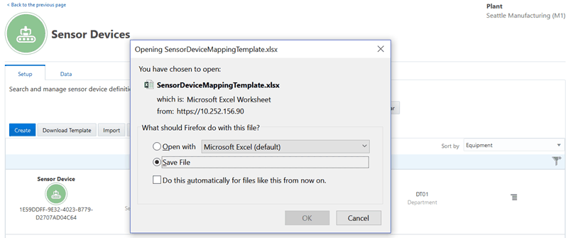
Use the given instructions in the template to enter the mandatory components of the parent header information, and equipment contextualization. Optionally, enter child paramenter information and work order contexualization. Before saving the file, make sure you are in the Mapping sheet and save the file in the CSV format.
-
Navigate to the Import Mapping page.
In the Setup tab of the Sensor Devices page, click Import
-
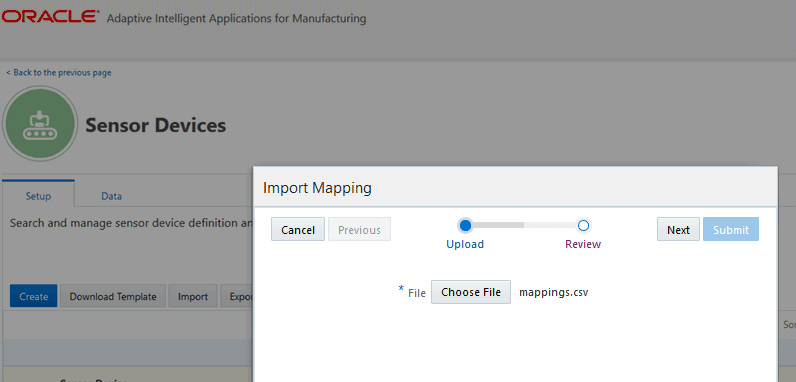
In the Import Mapping page, click Choose File, in the Import Mapping page to browse and select your saved file.
-
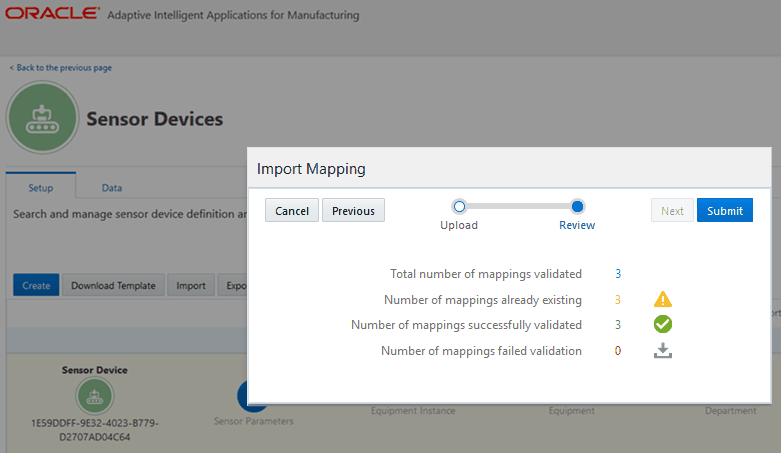
Click Next. Review the following information:
-
Total number of mappings validated
-
Number of mappings already existing
-
Number of mappings successfully validated
-
Number of mappings failed validation.
-
-
To complete the import, click Submit.
To export sensor device mappings
-
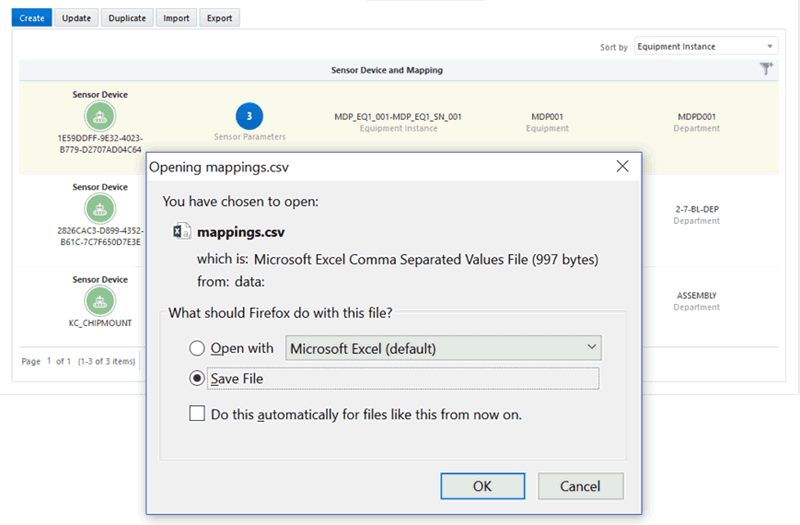
The Export functionality exports all mappings for the selected organization that appear in the Sensor Devices page. To reduce the number of mappings you want to export, use the search criteria to select specific mappings. Click Export.
-
The sensor device mapping definition you selected is exported to a CSV file. Use the browser's dialogue box to save the exported sensor device mapping in the CSV format.
Uploading CSV Files Using the Sensor Devices Data User Interface
Oracle Adaptive Intelligent Apps for Manufacturing provides specific templates which you can download and use to add sensor device data information. You can then upload the CSV format files using the Sensor Devices Data user interface.
Uploading CSV Files Using the User Interface
Use the Data tab of the Sensor Devices Page to import sensor device data by downloading and using the Stream data and Alert data templates which are provided.
To use the Data tab
-
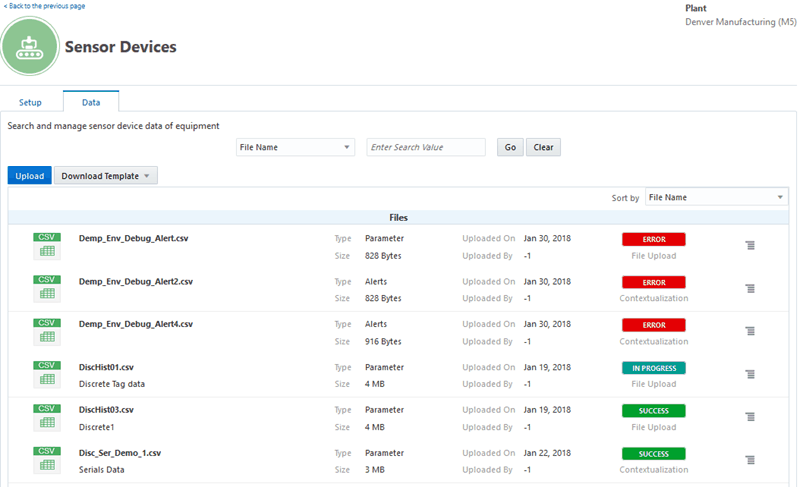
From the Home Page, click Insights or Predictions, then Data Ingestion link, then Sensor Devices Data, and then the Data tab. Alternatively, from the Home page, click Setup, then Sensor Devices, and then the Data tab.
To download file templates
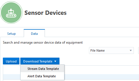
You can download the file template for either stream data or alert data in xlsx format. Use the same file template for both discrete and process manufacturing organizations. Follow the instructions provided in the templates to ensure you enter the required fields in the specified data formats.
-
From the Download Template drop-down list, select one of the following templates:
-
Stream Data Template
-
Alert Data Template
Review the Read Me instructions in the template, add information in the mandatory columns, and save the file in the required CSV format to your preferred location in your local drive.
-
To upload sensor data files
-
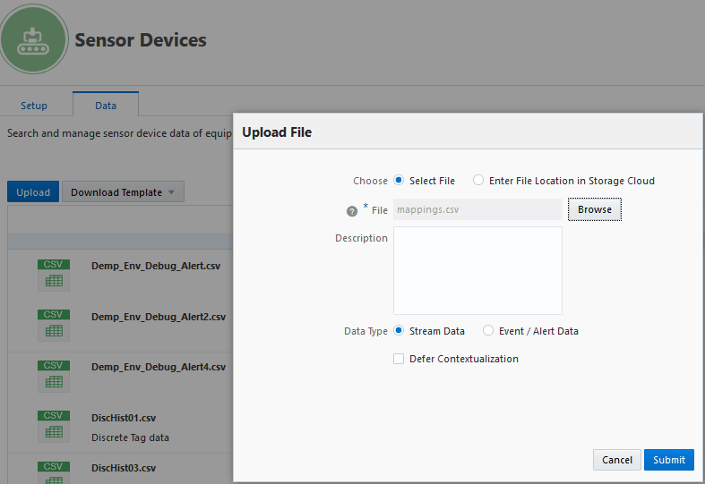
In the Data tab, Click Upload. The Upload File page appears. Use the Upload File page to upload a CSV file.
-
Choose one of the following options:
-
Select File to upload a file from your local drive.
-
Enter File Location in Storage Cloud to specify the file location where you have already uploaded the file in Oracle Storage Cloud.
-
-
When selecting the file from the local machine, click Browse or enter the file path in the File field.
When selecting the file from the Storage Cloud, provide the location of the file in Storage Cloud. The URL format should be similar to Container/subfolders/filename.csv.
For example: NTAIAMFG1825DEV1BDCSCE/aimfg/custom/Machine_Data_With_Tags_Pre_Uploaded.csv. Note that this example of the file path depicts the case where Oracle Data Transfer Service was used to import sensor data to Storage Cloud. In this case, the URL or container name must be obtained from Oracle Data Transfer Service.
Additional Information: Oracle Data Transfer Service offers a convenient way to quickly transfer terabyte up to petabyte-scale datasets to Oracle Cloud Infrastructure. For more information, refer to Oracle Cloud Storage Features.
-
Optionally, enter information in the Description field.
-
Depending on the data you are uploading, select one of the following Data Types:
-
Stream Data
-
Event/Alert Data
-
-
Optionally, select Defer Contextualization to only upload the file and defer contextualization processing of the sensor data.
-
Click Cancel if you do not want to upload the file. Click Submit to upload the file.
If you selected Defer Contextualization, select Run Contextualization from the Action icon to start contextualization processing of sensor data, after the file is successfully uploaded.
If you did not select Defer Contextualization, contextualization processing of sensor data starts after successful upload of the file.
Note: Contextualization processing can run on one file at a time. Select Run Contextualization from the Action icon after successfully uploading the file. When you upload multiple files, the application processes the data contextualization of one file after another file in the file upload sequence. For example, the data contexualization of the second file you upload, will run once the data contextualization of the file you uploaded before it is complete.
-
When you click Submit, the file appears in the List page, along with the file details, status, and possible actions.
View the status of the file upload that displays in the Sensor Data page, which can appear as In Progress, Success, or Error. After successfully uploading the file and completing contextualization processing, the status of the contextualization displays as Pending, In Progress, Success, Warning, or Error.
-
Click the Action icon for a file, then perform one of the following actions:
-
Run Contextualization
-
Download Contextualization Error Records
-
View Contextualization Status
-
View File Details
-
Download File
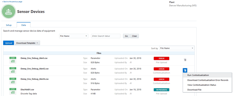
Note that the options in the Action icon are enabled or disabled based on the status of file upload or contextualization processing.
Upload Status Processing Status Run Contextualization Download Contextualization Error Records View Contextualization Status Download File File Details File Upload SUCCESS Enabled Disabled Disabled Enabled Enabled File Upload ERROR Disabled Disabled Disabled Disabled Enabled Contextualization SUCCESS Enabled Disabled Enabled Enabled Enabled Contextualization ERROR Enabled Enabled Enabled Enabled Enabled Contextualization WARNING Enabled Enabled Enabled Enabled Enabled Downloading Files:
-
You can downloaded a file only when it is successfully uploaded to Storage Cloud.
-
You can download the CSV file in GZ zipped format.
Downloading Contextualization Error Records:
-
When contextualization fails, a CSV file with records of the errors is generated, listing the error code and error message for each error record.
-
You can fix the errors in a generated error file and upload it as a new file. You must remove the error code and error message columns from the file.
Viewing Contextualization Status:
-
You can view the number of data points uploaded which have been contextualized successfully, or have errors.
-
You can view the summary of contextualization by organization, department, equipment, sensor, work order, operation, and processing information.
File Details:
The file you download has the following details:
-
File Name: Name of the data file.
-
Description: Description of the file.
-
Type: Data file type, whether it contains Stream or Alert data.
-
Size: Data file size.
-
Uploaded On: File upload date.
-
Stage: Step completed in the upload process, such as File Upload or Contextualization.
-
Status: Status of the file upload, such as ERROR, WARNING, or SUCCESS.
-
Error Message: High-level summary of the upload error message. This message only appears when the import status is ERROR.
-
Uploading and Processing Sensor Device CSV Files Using REST Web Services
Oracle Adaptive Intelligent Applications for Manufacturing provides four REST services to import and process sensor device data using CSV data files. The seeded templates must be downloaded, data entered as suggested in the template guidelines, and saved as a CSV file.
Sensor Device Data Ingestion supports the following REST services:
-
Uploading sensor device data files to Storage Cloud. For general information about uploading sensor device data files, see: Uploading CSV Files Using the Sensor Devices Data User Interface.
-
Starting contextualization processing of sensor device data files in Storage Cloud. For general information about contextualization processing, see: Processing Sensor Devices Data and Contextualization.
-
Retrieving the contextualization status details of the uploaded file.
-
Downloading the error records or the contextualization summary report file.
To use REST web services, a user must have access to Oracle Identity Cloud Service with either the Identity Domain Administrator or Application Administrator role. The user must first register the AIAMFG Client Application in Oracle Identity Cloud Service, then use a third-party client such as Postman to access REST web services. See: Appendix: REST Web Services, Oracle Adaptive Intelligent Apps for Manufacturing User's Guide.
Uploading sensor device files to Storage Cloud
You can upload sensor device data files to the Storage Cloud.
URL:
<host:>/vof/v1/mdap/pub/devicedata/upload
Request Parameters:
| Parameter Name | Description | Type | Required |
| json | A file containing the JSON payload, similar to the example shown below. | File | Yes. |
| files | CSV files containing data to import. | File | Yes. |
JSON Payload Request Example:
Input:
{
		"files" : [
        				{
								"fileName": "1.csv",
								"fileDescription" : "file description here",
								"fileType" : "parameter/alerts",
								"organizationCode":"<code>",
								"deferContextualization":"Y or N. N is default",
								"storageCsPath":"optionally refer to a file in cloud storage to create metadata for contextualization"
							},
       					{
								"fileName": "2.csv",
								"fileDescription" : "file description here" ,
								"fileType" : "parameter/alerts",
								"organizationCode":"<code>",
								"deferContextualization":"Y or N. N is default",
								"storageCsPath":"optionally refer to a file in cloud storage to create metadata for contextualization"
							},
  					]
}
Response Body Example
{
		"files" : [
        				{
								"fileName": "1.csv",
								"fileDescription" : "file description here" ,
								"fileType" : "parameter/alerts",
								"organizationCode":"<code>",
								"deferContextualization":"Y or N. N is default",
								"storageCsPath":"optionally refer to a file in cloud storage to create metadata for contextualization",
								"contextualizationStatus":"Pending or Error, shown only if deferContextualization is not set or is set to N",
								"uploadStatus":"Success or Error", "failureReason": "display an appropriate message string if error occurs"},
       				 {
								"fileName": "2.csv",
								"fileDescription" : "file description here" ,
								"fileType" : "parameter/alerts",
								"organizationCode":"<code>",
								"deferContextualization":"Y or N. N is default",
								"storageCsPath":"optionally refer to a file in cloud storage to create metadata for contextualization",
								"contextualizationStatus":"Pending or Error, shown only if deferContextualization is not set or is set to N",
								"uploadStatus":"Success or Error", "failureReason": "display an appropriate message string if error occurs"
							},
 					]
 }
Starting contextualization processing of the sensor device data files in Storage Cloud
Start contextualization processing of the sensor device data upon successful completion of the file upload to Storage Cloud. Contextualization processing runs on one file at a time.
URL:
<host:>/vof/v1/mdap/pub/devicedata/contextualize/<filename>
Request Parameter:
filename
Response Payload:
Input:
"fileName" as part of the url path parameter
Output:
{
    "fileName": "fileName",
    "contextualizationStatus": "Submitted" or "Error"
    //If the contextualization job fails to submit, then a failureReason property is added to the payload
}
Retrieving the contextualization status details of the uploaded file
This service retrieves the number of data points uploaded which have been contextualized successfully, or have errors.
URL:
<host:>/vof/v1/mdap/pub/devicedata/summary/<fileName>
Request Parameter:
filename
Response Payload:
Input:
"fileName" as part of the url path parameter
Output:
 {
    "fileName":<fileName>
		"fileType":"Parameter" or "Alerts",
     "fileDescription":<optional file description>,
     "uploadStatus" : "Success" or "Error",
     "contextualizationStatus" : "Success", "Error", "Pending", or "In_Progress",
     "dataPointsContextualizatedWithEquip":<number of data points>,
     "dataPointsContextualizatedWithWorkOrder":<number of data points,>
     "dataPointsContextualizatedWithSerial":<number of data points>,
     "failedDataPoints:<number of data points failed>,
     "totalDataPoints":<total number of data points>,

     //If one or more data points fails while executing this REST web service, then a failureReason property is added to the payload.
Example output if a file is not submitted for contextualization:
{
    "fileName": "SampleData02.csv",
    "fileType" : "Alerts"
    "uploadStatus": "ERROR",
    "failureReason": "File column names or values do not match with the template."
 }
Example output if a file is submitted for contextualization, but has errors:
 {
    "fileName": "SampleData02.csv",
    "fileType" : "Parameter",
    "uploadStatus": "Success",
    "contextualizationStatus": "ERROR",
    "dataPointsContextualizatedWithEquip": 0,
    "dataPointsContextualizatedWithSerial": 0,
    "dataPointsContextualizatedWithWorkOrder": 0,
    "failedDataPoints": 36000,
    "totalDataPoints": 36000,
    "failureReason": "Contextualization has failed for all records in the file. You can download the contextualization error records and check the issue."
 }
Downloading the error records or contextualization summary report file
When contextualization fails, a CSV file with records of the errors is generated, listing the error code and error message for each error record. This REST web service downloads this error file. Optionally, you can fix the errors in the generated error file and upload it as a new file after removing the error code and error message columns from the file.
Alternatively, this REST web service downloads a report file that summarizes contextualization by organization, department, equipment, sensor, work order, operation and the processing information.
URL
<host:>/vof/v1/mdap/pub/devicedata/download/<fileName>/<fileType>
Request Parameters:
| Parameter Name | Description | Type | Required |
| fileName | The full file name with extension (such as SampleData1.csv). | String | Yes. |
| fileType | Use the value "summary" to download a summary report file. Use "error" to download the error records file. | String | Yes. |
-
The fileName and fileType parameters are case sensitive.
-
When downloading a file using a REST client, such as Postman, or a command line tool, such as cURL, specify a target file name with a *.gz extension, if necessary. For example, <fileType>_<fileName>.gz or summary_SampleData1.csv.gz. If downloading a file using a browser, a target file name is unnecessary.
Response Payload
-
Response type: application/zip
-
Content Type: attachment
-
File Name: <fileType>_<fileName_with_extension>.gz
Warning: If the download fails, the API returns the file name "fail_<fileName>.csv", which contains an explanation of the download failure.
Processing Sensor Devices Data and Contextualization
Once the sensor data is uploaded to Oracle Storage Cloud, the stream and event/alert data is processed for contextualization, event identification and summarization.
Note: The application checks sensor data for any duplicate data and does not save it in the contextualized data repository. Duplicate records, such as sensor data with the same sensor device ID, parameter name, and reading date within an uploaded file are not saved. Similarly, when data already exists in the repository for equipment, sensor device ID, parameter name, and period, the newly uploaded file data is not saved.
Processing Sensor Data
The following topics describe how the two types of sensor device data, Stream data and Alert data, are processed:
Processing Stream Data
-
The Data Contextualization Processor applies equipment context information to the stream data.
-
The Data Contextualization Processor then applies the work order context to the stream data that has already been contextualized with the equipment information.
-
The Event Identification Processor identifies events and applies the selected time series feature sets. The derived alerts for machine event analysis are seen in the Factory Command Center and Genealogy and Trace Timeline Viewer.
Processing Alert Data
-
The Data Contextualization Processor applies equipment and work context information to the alert data, which then appears in the Factory Command Center.
-
The Alert Summarization Processor merges the continual occurrent alert data points to one record with the start and end time. This information appears in the Genealogy and Trace Timeline Viewer.
Processing Data Contextualization
Data contextualization enriches stream data and alert data from sensor devices with equipment and work order context attributes so that the machine data can be associated to the entities defined in the EBS instance.
Contextualizing data includes setting up contextualization for deriving equipment and work order information:
-
Equipment Contextualization: Equipment context includes information about the organization code, department code, equipment code, and equipment instance code.
-
Work Order Contextualization: Depending on whether it is a process or discrete manufacturing organization, work order context includes information about the work order number operation or step, activity, and serial number.
The three available seeded context types provided are:
-
Equipment context type only (Context Type = 1) : The contextualized data includes only information on organization code, department code, equipment code, and equipment instance code.
-
Work order context type only (Context Type = 2): The contextualized data includes information on work order number operation or step, activity, and serial number.
-
Equipment and work order context type (Context Type = 3): The contextualized data includes both equipment and work order contexts.
The following table details the context values derived from the selected seeded context type:
| Context Value | Context Type = 1 | Context Type = 2 | Context Type = 3 |
| OrganizationCode | Organization Code | - | Organization Code |
| DepartmentCode | Department Code | - | Department Code |
| EquipmentCode | Equipment Code | - | Equipment Code |
| EquipmentInstanceCode | Equipment Instance Code | - | Equipment Instance Code |
| WorkOrderNumber | - | Work Order Number | Work Order Number |
| OperationSequence | - | Operation or Step | Operation or Step |
| Activity | - | Activity | Activity |
| SerialNumber | - | Serial Number | Serial Number |
Equipment contextualization helps to obtain equipment information found either in sensor device messages or sensor device mapping setup.
Work and Serial contextualization helps to obtain work order information from the sensor device messages or from ERP based on the actual or planned time frame of work execution. For machine alerts, equipment contextualization is sufficient to show the data in the Factory Command Center and Genealogy and Trace pages.
You can specify equipment contextualization and work order contextualization when setting up sensor device mappings.
See: Setting Up Sensor Device Mappings.
Equipment Contextualization
The equipment contextualization processes sensor device data and associates each sensor message data with equipment information. The mandatory equipment contextualization processor contextualizes machine stream raw data and alerts with equipment information. It stamps each message with equipment instance, equipment, department (in the case of discrete manufacturing) and organization to the sensor readings data.
Following are the two types of equipment contextualization, shown in order of priority:
-
Use equipment information found in sensor device message.
-
Use equipment information based on sensor device mapping setup.
When the contextualization is based on the sensor device message, the sensor sends the readings with the equipment context information. The processor picks context information from the sensor readings and validates the codes in the ERP instance. If the context information is valid, the contextualization is successful. If it is not valid, the record is marked as an error.
The following table shows the placeholders for context attributes for equipment contextualization only:
| Context Value | Context Type = 1 |
| OrganizationCode | Organization Code |
| DepartmentCode | Department Code |
| EquipmentCode | Equipment Code |
| EquipmentInstanceCode | Equipment Instance Code |
The following table describes equipment contextualization status:
| Status | Description |
| Success | Equipment information is derived from sensor device messages or the sensor device mapping setup and the equipment contextualization is complete. These records are available for the Factory Command Center and the Timeline Viewer and are ready for further processing for work order and serial unit contextualization. |
| Error | Equipment contextualization fails if the equipment information in sensor device messages is invalid or the sensor device mapping setup is not available. These records are not stored in the repository. The contextualization also fails when the record is duplicated in the file or the record exists in the repository. |
Work Order Contextualization
Once the equipment contextualization is complete, the work order contextualization process begins.
Work order and serial (for discrete serialized manufacturing) contextualization contextualizes machine stream data and alert data with work order (and serial if serialized manufacturing) information. It stamps work order, operation, step, and serial (in case of discrete serialized manufacturing) on the sensor readings.
It is not mandatory to choose a work and serial contextualization method as in some cases the need is to only monitor the stream data and alert data and not use it for model building purposes.
Following are the three types of work order contextualization, shown in order of priority:
-
Use work order information found in sensor device message.
-
Use work order information based on actual time frame of work execution.
-
Use work order information based on planned time frame of work execution.
Work order contextualization is processed according to the priority sequence chosen in the sensor device mapping setup. Based on the preference, it picks the context from either the sensor device message,, work order actuals, or work order planned and validates context for work order, operation/step, activity and serial number (in case of discrete serialized manufacturing).
In case of contextualization using work order information found in the sensor device message, the work order information is validated with work orders whose plan schedule falls within the range of 30 days before and after the sensor device message reading date.
Note: You can choose to change the order or remove all the methods if work and serial contextualization is not required. This is applicable in cases where the need is to only monitor the parameters or alerts but not use them for a model building process. You cannot select the priority of work order planned over work order actuals as the work order actuals takes preference in majority of use cases.
The following table shows the placeholders for context attributes for work order contextualization only as well as both equipment and work order contextualization:
| Context Value | Context Type = 2 | Context Type = 3 |
| OrganizationCode | - | Organization Code |
| DepartmentCode | - | Department Code |
| EquipmentCode | - | Equipment Code |
| EquipmentInstanceCode | - | Equipment Instance Code |
| WorkOrderNumber | Work Order Number | Work Order Number |
| OperationSequence | Operation or Step | Operation or Step |
| Activity | Activity | Activity |
| SerialNumber | Serial Number | Serial Number |
The following table describes work order contextualization status:
| Status | Description |
| Success | Work order information context is derived from the sensor device message, actual work order, or plan work order and the contextualization is complete. These records are available for downstream applications. In case of serialized manufacturing, the serial unit information is derived from sensor device message. |
| Error | Work order contextualization fails as the work order information in sensor device message is invalid or actual/plan work order is not available. These records are not available for analysis. |
You can view the status of contextualization processing for successfully uploaded sensor data file in the Data tab of the Sensor Devices page. The status of the contextualization is shown as Pending, In Progress, Success, Warning, or Error.
See: Uploading CSV Files Using the Sensor Devices Data User Interface
Processing Event Identification and Alert Data Summarization
Event identification processing is run on contextualized stream data and generates machine alerts. The event identification processor is run in batch mode on the stream data and derive alerts. You can process event identification by selecting the feature set for machine event analysis usage when setting up sensor device mappings. Both the derived alerts from the stream data using event identification processing and the direct alerts from the equipment is summarized and stored for analysis.
Event Identification in Stream Data
The Stream Sample Interval feature enables the calculation and generation of events based on intervals from the stream data.
The event identification processor uses stream sample interval defined for the parameter in the sensor device mapping setup to identify if there is any break in the stream data. If a break is identified in the stream data, the records are split as separate time series data, and event identification processing is applied on each block of data.
Note: In case the stream sample interval value is different from the stream data readings interval, the stream data is split into multiple blocks and event identification processing is applied. However, when the split exceeed 10 blocks, the event identification processing is stopped for this stream data in order to detect events correctly. Event identificaiton processing will continue for other stream data which is coming at right interval and matching with steam sample interval.
It is important that users specify the stream sample interval same as the actual time interval of sensor readings. If the sample interval is different, then the event identification processing may fail due to performance issues.
Summarization of Alert Data
Machine events can be indirectly derived from a time series sensor stream data. Time series feature sets defined for Machine Event Analysis usage help derive such events. These time series features set can be used for machine event analysis to enable event identification based on the simple functions you select like Above Threshold Alert or the advanced SAX Pattern Alert when creating a time series feature set.
Event identification processing allows the following time segment and function options to choose when defining a time segment feature set for Machine Event Analysis usage:
-
Time Segment: Full is the only time segment available as the streaming data will be analyzed for any events in the duration of the work order and operation.The time segment step is retained in the page for consistency in the navigation.
-
Simple Functions: Only the following threshold violation rules are allowed:
-
Above threshold alert
-
Below threshold alert
-
Within range alert
-
Outside range alert
-
-
Advanced Functions: Only SAX pattern alert is allowed.
Note: In the case of Event functions, you can specify the value aggregation function like minimum, maximum or average for generating the value of the event. You can specify after an event is matched whether to skip to the last data point or skip to the next data point for checking next matching pattern.
Above Threshold Alert example:
You can specify, after an event is matched, to skip to the last data point or skip to the next data point for the following temperature readings:
| Time | T1 | T2 | T3 | T4 | T5 | T6 | T7 | T8 |
| Temperature Reading | 10 | 25 | 23 | 34 | 11 | 12 | 10 | 11 |
If you have defined the Above Threshold value as 20 and selected the Value Aggregation function as Maximum, based on the temperature readings given above, the events are generated based on the option you choose for After Match.
If the After Match is Skip to Next, the following three events are generated:
-
Event E1 - Start Time: T2, End Time: T2, Value: 25
-
Event E2 - Start Time: T3, End Time: T3, Value: 23
-
Event E3 - Start Time: T4, End Time: T4, Value: 34
If the After Match is Skip to Last, one event is generated:
-
Event E1 - Start Time: T2, End Time: T4, Value: 34
See the following topics in Oracle Adaptive Intelligent Apps for Manufacturing User's Guide:
-
Using Time Series Feature Sets
-
Setting Up Time Series Feature Sets
Using Sensor Devices Data Templates
AIAMFG provides sensor device data templates for stream data and alert data which can be used by process manufacturing and discrete manufacturing organizations. Download the templates from AIAMFG and then enter the data as recommended into the spreadsheet templates. The following data templates are available for sensor device data:
Alert Data (EventAlertDataTemplate.xlsx)
| Field Name | Required | Data Type | Length (Max) | Description | Sample Data |
| Reading Date | Y | Number | Reading Date field should be in Epoch milliseconds format (number of milliseconds elapsed since Unix epoch) or the normal date and time format. | 1494403200000 (Epoch format) 2017-02-11T07:40:00.013+0800 | |
| Sensor Device ID | Y | Char | Unique ID for the sensor device | 7CCBC4D9-FD52-4919-8212-219DBFCF0B2E | |
| Alert Type | Y | String | See Alert Type Values table for more details. | MachineStatus | |
| Alert Value | Y | Char | See Alert Type Values table for more details. | UP | |
| Context Type | Number | 1 - If only equipment context information is available. 2 - If only work order context information is available 3 - If both equipment and work order context information is available | General Electrics | ||
| Organization Code | Char | 4 | Short alphanumeric code of the organization to which the item belongs. Required for equipment contextualization | M5 | |
| Department Code | Char | Required for Discrete Manufacturing | Machining | ||
| Equipment Code | Char | Required for equipment contextualization | 3D-PRINT | ||
| Equipment Code Instance | Char | Required for equipment contextualization | |||
| Work Order Number | Char | Required for work order contextualization | 7320 | ||
| Operation Sequence | Number | Required for work order contextualization | 10 | ||
| Activity | Char | Process - Required for work order contextualization. Discrete - Not applicable | ACT | ||
| Serial Number | Char | Process - Not applicable | S000000 | ||
| Additional Attributes | Char | See Additional Attributes Values table for more details. | {"current_quantity":10,"overall_quantity":100} |
Stream Data (StreamDataTemplate.xlsx)
| Field Name | Required | Data Type | Length (Max) | Description | Sample Data |
| Reading Date | Y | Number | Reading Date field can be in Epoch milliseconds format (number of milliseconds elapsed since Unix epoch) or the normal date and time format. | 1494403200000 (Epoch format) 2017-02-11T07:40:00.013+0800 | |
| Sensor Device ID | Y | Char | Unique ID for the sensor device | 7CCBC4D9-FD52-4919-8212-219DBFCF0B2E | |
| Parameter Name | Y | Char | Sensor Parameter Name defined in the device setup. | Internal Temperature | |
| Parameter Value | Y | Char | Parameter Value | 119 | |
| Organization Code | Char | 4 | Short alphanumeric code of the organization to which the item belongs. Required for equipment contextualization | M1 | |
| Department Code | Char | Required for Discrete Manufacturing | Machining | ||
| Equipment Code | Char | Required for equipment contextualization | 3D-PRINT | ||
| Equipment Code Instance | Char | Required for equipment contextualization | |||
| Work Order Number | Char | Required for work order contextualization | 7320 | ||
| Operation Sequence | Number | Required for work order contextualization | 10 | ||
| Activity | Char | Process - Required for work order contextualization. Discrete - Not applicable | ACT | ||
| Serial Number | Char | Process - Not applicable | S000000 | ||
| Context Type | Number | 1 - If only equipment context information is available. 2 - If only work order context information is available 3 - If both equipment and work order context information is available | 2 |
Alert Type Values
| Alert Types | Values | Meanings |
| MachineStatus | OFF, UP, DOWN, IDLE, IN-USE, FAULTED | UP: State of the machine when it is warming up, when just turned on. DOWN: State of the machine when it is down. Additional Attribute: resourceDownCode IDLE: Optional, state of the machine when it is powered on but is not working. If the sensor device is unable to provide the status of the machine, machine status will be determined based of the ERP context information and set to a status of UP. IN-USE: Optional, state of the machine when it is running. If the sensor device is unable to provide the status of the machine, machine status will be determined based of the ERP context information and set to a status of UP. |
| JobStatus | STARTED, PAUSED, RESUMED, COMPLETED | STARTED: Job has started and is in-progress (Additional attributes 'current_quantity' and 'overall_quantity' are applicable) PAUSED: Job has paused (Additional attribute 'current_quantity' and 'overall_quantity' is applicable) RESUMED: Job has resumed (Additional attribute 'quantity' is applicable) COMPLETED: Job has been completed (Additional attribute 'quantity' is applicable) |
| PatternMatch | <<Stream Parameter Name>> Additional Attributes:
| |
| Threshold Violations | <<Stream Parameter Name>> Additional Attributes:
| |
| DoorState | OPEN, CLOSE | |
| PowerState | UP, DOWN |