17 Pipes
This chapter describes how you can use Pipe entities in Oracle Communications Unified Inventory Management (UIM) to represent connectivity in your inventory.
Note:
This chapter includes examples of implementing channelized and packet connectivity by using Pipe entities. These examples are still valid technically, but Oracle recommends using Connectivity entities for these technologies. Connectivity entities offer more functionality and efficiency than pipes. See "When to Use Pipes" for more information.When to Use Pipes
You can use Pipe entities, Connectivity entities, or both to represent connectivity in your inventory.
Most common telecommunications connectivity scenarios can be implemented by using Connectivity entities, which are extensions of Pipe entities. Connectivity entities include more built-in functionality than pipes.
Pipe entities are designed for maximum flexibility, so you must define all of their attributes. Connectivity entities, on the other hand, take advantage of pre-defined rate codes, technologies, functions, and other attributes.
See the following chapters for information about Connectivity entities:
You can still implement solutions by using pipes directly, however. For example, pipes might be applicable in situations such as:
-
Existing UIM implementations. If you previously modeled connectivity using pipes, you can continue to use those entities. Pipe and Connectivity entities can coexist in the same inventory. Pipes can enable Connectivity entities and Connectivity entities can enable pipes.
-
Physical connections, such as cable pairs and local loops.
-
Other forms of connectivity not implemented by other entities.
Understanding Pipes
Pipes are the base entities for representing connectivity in UIM. You can use pipes to represent both physical connectivity and logical connectivity. For example, you can use a pipe to represent the logical connectivity of a 64 Kbps PVC (Permanent Virtual Circuit) service trail. You can also use a pipe to represent the physical connectivity of a 100-pair cable.
Pipes can have bandwidth, a type of capacity that specifies the speed and amount of data that can be transported over the pipe. In the case of digital signals, capacity is defined by the speed of the signal. See "Understanding Capacity and Signal Structure" for more information.
Every pipe has two termination points that represent its two ends. Signals travel over pipes from one termination point to the other. The termination points are created automatically when you create a pipe in UIM.
Termination points can be associated to various kinds of entities, such as device interfaces and ports. This kind of association is called termination. A pipe and its termination points are terminated on the entities to which the pipe termination points are associated.
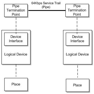
For example, you can terminate a pipe and its termination points on device interfaces that are provided by logical devices. The logical devices can have place associations to give the termination a geographic context. The place association ensures that the pipe and its associated devices are included in the UIM topology. See "Topology" for more information.
Figure 17-1 shows resource and place terminations for a 64 Kbps service trail pipe's termination points.
See "Defining Pipe Specifications" for more information about designing Pipe specifications and creating Pipe entities.
Understanding Pipe Relationships
You use relationships between pipes to define how connectivity is structured in your inventory. Two important types of pipe relationships are provides and enables.
Provides Relationships
A provides relationship exists when one entity supplies one or more other entities that cannot exist on their own. You create provides relationships by associating a signal structure with a pipe or by building parent-child hierarchies of pipes.
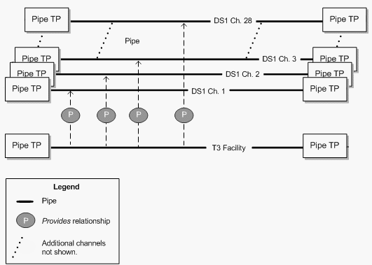
For example, a TDM facility pipe provides channel pipes through signal structures. In this case, UIM automatically builds hierarchies of child pipes based on the signal structure. See "Understanding Capacity and Signal Structure" for more information about signal structures.
Similarly, a cable pipe provides cable-pair pipes. The child pipes can be defined by the parent pipe's specification. They can also be added manually in UIM. See "Configuring and Implementing Child Pipes for the Cable/Pair Model" for information about provides relationships in cable and cable-pair pipes.
Figure 17-2 shows a provides relationship between a T3 facility and the 28 DS1 channels that it provides.
Enables Relationships
A pipe enables another pipe when it supports the transport of data by the other pipe. In its simplest form, enablement refers to the association of a physical resource, such as a cable pair to a customer service, such as POTS. For example, when you enable a local loop by associating it with a cable pair, you are specifying the physical resource that realizes the connectivity of the customer service.
Similarly, channels provided by a facility can enable a service trail. For example, a 100 Mbps service trail represents the connectivity of some service provided to a customer. You can enable the service trail by associating it with two STS1 channels.
When a pipe enables another pipe, it can provide capacity to the enabled pipe. For example, the STS1 channels mentioned in the previous paragraph supply their capacity, defined in the signal structure of their parent OC3 facility pipe, to the service trail they enable. See "Understanding Capacity and Signal Structure" for more information.
Pipes can also be enabled by two separate connectivity paths. For example, multiple paths can exist in SONET/SDH. See "About Multiple Enablement" for more information.
Enables relationships also exist between the pipe termination points of enabling and enabled pipes. In the simplest case, where a single pipe enables another pipe, the termination points of the enabling pipe enable the termination points of the enabled pipe. Pipes can also be enabled by a series of connected pipes that form a connectivity path. The beginning and ending termination points of the connectivity path are therefore not on the same pipe. In this case, the beginning termination point is on the first pipe in the connectivity path and the ending termination point is on the last pipe.
You can enable pipes either manually or automatically by using path analysis. See "Enabling Pipes" for more information.
Provides and Enables Relationships in Combination
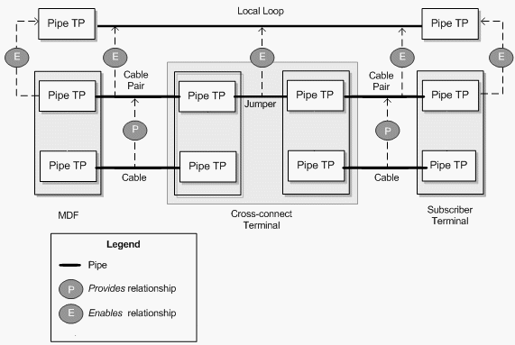
Figure 17-3 illustrates how the different types of relationships work together. This example shows the enablement of a local loop by cable pairs. The cable pairs are provided by cables. The local loop trail pipe is enabled by the following pipes that form a continuous connectivity path:
-
A feeder cable pair that connects an MDF to a cross-connect terminal.
-
A cross-connect in the cross-connect terminal. UIM creates cross-connects when two pipes that enable the same trail pipe are terminated on the same physical device, equipment, or logical device. See "About Connectivity Gaps in Pipe Enablement" for more information.
-
A distribution cable pair that connects the cross-connect terminal to the subscriber terminal.
The termination points of the parent cable are mapped to the termination points of the cable pairs they provide. The originating termination point of the first cable pair enables the originating termination point of the local loop, while the end termination point of the second cable pair enables the end termination point of the local loop.
About Multiple Enablement
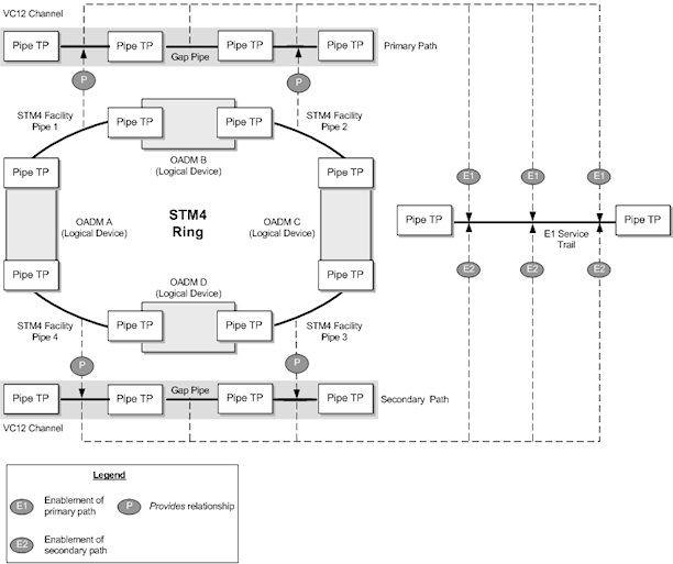
The previous examples describe the enablement of pipes by a single connectivity path. It is also possible for a pipe to be enabled by two separate connectivity paths. This capability is required in ring-based network topologies, such as SONET/SDH, which include both a primary and a secondary path.
Note:
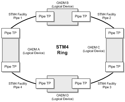
This section describes how you can use Pipe entities to represent an SDH network. Because SDH is a TDM technology, you can also use Channelized Connectivity entities and their specialized functionality for this purpose. See Chapter 14, "Channelized Connectivity" for more information.For example, consider a single-ring SDH network with four optical add-drop multiplexers (OADMs). The four OADMs are modeled as logical devices with device interfaces on which four STM4 facility pipes are terminated. Figure 17-4 illustrates such a ring.
To enable an E1 service trail from OADM A to OADM C with both a primary path and a secondary path, you can use two connectivity paths:
-
From OADM A through OADM B to OADM C
-
From OADM A through OADM D to OADM C
This connectivity is supplied by VC12 channels provided by the STM4 facility pipes and by gap pipes as shown in Figure 17-5.
Note:
For visual clarity, maps and enables relationships between pipe termination points are not shown in Figure 17-5.Multiple enablement is also available in more complex ring topologies such as single-homed and dual-homed subtended rings. See "About Network Topologies" and the Design Studio Help for more information.
Multiple enablement can be done manually or automatically by using path analysis. See "Enabling Pipes" for more information.
Understanding Pipe Configurations
Pipe configurations enable you to specify pipe enablements and termination point resource assignments that change over time. For example, a service trail could be enabled by a particular connectivity path when it is first created. As the network evolves, new enablement possibilities may emerge. By versioning the service trail pipe configurations, you can update the enablement and specify when the change becomes effective. Pipe configurations can include multiple enablements, as in SONET or SDH. See "About Multiple Enablement" for more information.
Pipe configurations are similar to other entity configurations in concept, but they have some special features:
-
They are available only for pipes that have specifically been designated as versionable.
-
Pipe configuration specifications are limited to specification options related to transport and termination point resource assignment.
-
When you define a pipe configuration specification, you can specify that only entities based on a particular Pipe specification can be used for enablement. Path analysis returns only pipes based on the designated specifications when it finds connectivity paths.
-
You can specify a particular type of device or equipment that must be included as an intermediate node in the connectivity path that enables the pipe. For example, when you enable a DSL service trail pipe from a subscriber terminal to a local exchange or CO switch, path analysis would normally find the most direct path between the end points, bypassing the DSLAM. You can specify that a DSLAM entity must be included as an intermediate node. In this case, path analysis searches for paths that run from the subscriber terminal to a DSLAM and from the DSLAM to the switch.
-
See "Designing and Implementing Pipe Configurations" for information about designing and implementing pipe configurations. See "Enabling Pipes" for information about enablement, including path analysis.
Understanding Pipe Directionality
Some pipes have directionality, which defines the direction that signals or routes flow through a pipe. This might be necessary, for example, if the pipes enabling a service trail pipe share termination points in a way that causes ambiguity about the connectivity path. By setting the directionality of the service trail, you can resolve the ambiguity.
There are two independent directionality settings:
-
Signal directionality refers to the direction that signals flow on the pipe. Most pipes are bi-directional, meaning that signals flow in both directions. Other pipes are uni-directional, meaning that signals flow in one direction only. Examples of uni-directional pipes are alarm and control operation connections.
-
Routing directionality restricts or enables functions such as path analysis. For example, you can define a pipe as uni-directional for routing purposes to restrict the route of a connection from an originating point to a specific terminating point while avoiding certain path segments.
For example, you use routing directionality to ensure proper routing to and from the DSLAM in a DSL enablement. DSLAMs normally have two sides, a cable/subscriber side and a switch/office side. Pipes connect the two DSLAM sides to the MDF, where connections are made between the cable/subscriber pipe and the cable pair or local loop and between the switch/office pipe and the POTS switch. Routing directionality ensures that these MDF connections are made properly. The routing direction for the cable/subscriber-side pipes is from the MDF to the DSLAM. The routing direction for the switch/office-side pipes is from the DSLAM to the MDF.
You set the directionality of a pipe by specifying which termination point is the source (starting point) and which is the sink (ending point). Signals and routes flow from source to sink. Path analysis uses this direction information with the source of the query serving as the subscriber terminal device and the target as the switch device.
See the UIM Help for more information about setting pipe directionality.
About Connectivity Gaps in Pipe Enablement
A connectivity gap occurs in the design of a pipe trail when there is not sufficient information or continuity to complete a path.
UIM can automatically resolve these gaps during enablement in certain situations. Cross-connects are created when the two enabling pipes are terminated on device interfaces within the same logical device and at least one terminates on a sub-device interface. In other situations, UIM cannot resolve the gap and it remains part of the enablement.
UIM can automatically resolve these gaps during enablement in certain situations:
-
A trail-bound cross-connect is created when the two enabling pipes are terminated on device interfaces within the same logical device and at least one terminates on a sub-device interface.
-
A trail-bound jumper is created when the two enabling pipes are terminated on ports provided by a single Physical Device or Equipment entity or by two Physical Device or Equipment entities at the same property location.
In other situations, UIM cannot resolve the gap and it remains part of the enablement. See "About Interconnections" for more information about cross-connects and jumpers.
Connectivity gaps also exist for channelized connectivity, but are used in somewhat different ways. See "About Connectivity Gaps" for more information.
Understanding Capacity and Signal Structure
In UIM, capacity refers to the amount and type of resource that entities require or provide. You define the nature of the capacity, how it is measured, and how it is used. See "Capacity" for more information about capacity.
Note:
Pipes and signal termination points are the only UIM entities that can use the capacity framework by default.In the specific case of connectivity, capacity is bandwidth consumed or provided by pipes. When a pipe enables another pipe, its bandwidth can be consumed by the enabled pipe. Pipes can offer capacity in the following ways:
-
As a unit. For example, a cable pair's capacity can only be consumed as a whole by the pipe it enables. In this case, you do not explicitly define the pipe's capacity because it cannot be consumed in fractions or smaller units.
-
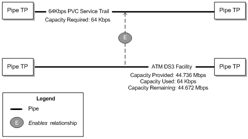
In fractions of capacity. For example, an ATM DS3 facility pipe provides a total capacity of 44.736 Mbps. This capacity can be consumed in variable amounts by pipes enabled by the facility. For example, a PVC service trail could use 64 Kbps of the DS3 pipe's bandwidth. See "Understanding Packet Capacity" for more information.
-
In increments, in the form of channels with unit capacity. TDM divides bandwidth into channels that can be consumed in whole or in part by other pipes. For example, a T3 facility pipe can provide a total of 44.736 Mbps divided into 28 D1 channel pipes of 1.544 Mbps unit capacity. You provide channelized capacity by associating a signal structure with the pipe. See "Understanding Signal Structures" for more information about signal structures.
These ways of providing and consuming capacity correspond to the three pipe models supported by UIM. See "Understanding Pipe Models" for more information.
Understanding Packet Capacity
For pipes based on packet connectivity, you define capacity by defining the pipe's capacity required (the amount of bandwidth it needs for its own enablement) and capacity provided (the amount of bandwidth it makes available to pipes that it enables). Some pipes have both capacity required and capacity provided because they can enable other pipes and also be enabled by other pipes. Other pipes, such as service trail pipes, have only capacity required because they are not used to enable other pipes.
Figure 17-6 shows an example of packet capacity usage. It depicts an ATM DS3 facility pipe enabling a 64 Kbps service trail. The DS3 pipe requires and provides 44.736 Mbps. The service trail consumes 64 Kbps, leaving the DS3 facility pipe with 44.672 Mbps of capacity that can enable other pipes. (For simplicity, the enablement of the ATM DS3 pipe is not shown.)
See "Configuring Capacity for Packet Facility Pipes" for information about designing and implementing capacity for packet pipes.
Understanding Signal Structures
Signal structures support connectivity by defining the capacity and channel hierarchy of TDM facility pipes. Signal structures can support North American (for example, T1 or OC12) and European (for example, E1 or STM4) digital signal rates. You should be familiar with the basics of these kinds of digital signal technologies before reading this section.
Note:
Channelized Connectivity entities use a different system for defining signal structures. See "About the UIM Signal Architecture" for more information.When you associate a signal structure to a Pipe specification, the capacity defined in the signal structure becomes available to pipes based on that specification and to the pipes they provide. The hierarchy of the signal structure determines the way this capacity can be distributed. For example, if you create a T3 signal structure comprising 28 DS1 channels, you can assign it to a T3 facility Pipe specification. That makes the 44.736 Mbps of capacity available to the facility pipe, to be distributed in 28 DS1 channels of 1.544 Mbps each.
You can configure signal structures so that channels can enable pipes that do not have exactly matching capacities. For example, in SDH, a VC3 channel signal of 51.840 Mbps can support a VC3 facility at 51.840 Mbps facility or an E3 facility at 34.368 Mbps. The entire channel is consumed, even if the enabled pipe uses less than the full capacity. Any remaining capacity is unavailable. See "Configuring Capacity with Signal Structures" and the Design Studio Help for more information.
Simple and Complex Signal Structures
Signal structures can be divided into simple and complex categories:
-
A simple signal structure has only two levels: a TTP (Trail Termination Point) and one level of CTPs (Connection Termination Points).
-
A complex signal structure has more than two levels: a TTP and two or more levels of CTPs. Each layer in the structure defines how its parent signal breaks down to a lower rate.
The distinction between simple and complex signal structures is important because it governs how channel pipes associated with signal structures are created in UIM.
-
When you create a pipe associated with a simple signal structure, all of the channels provided by the pipe are created automatically by UIM, even if they are not currently needed to provide capacity to pipes. Automatic creation of channel pipes is possible because there is no ambiguity about how these channels can be used. They can only be used individually.
For example, if a DS3 signal structure is mapped to a facility pipe, the 28 DS1 channel pipes provided by the facility are created automatically when you create a DS3 facility pipe. There is no ambiguity about how the DS3 will be channelized, so the channels can be created automatically.
-
In complex signal structures, the system cannot know in advance how channels will be used. A higher-level CTP may be mapped as a whole to a pipe, thus making its lower-level CTPs unavailable. Alternatively, low-level CTPs may be mapped individually, thus making its parent CTP unavailable as whole units. Because of this potential ambiguity, UIM creates channels for pipes with complex signal structures only when the channels are required.
See "Configuring Capacity with Signal Structures" for more information about working with signal structures in UIM.
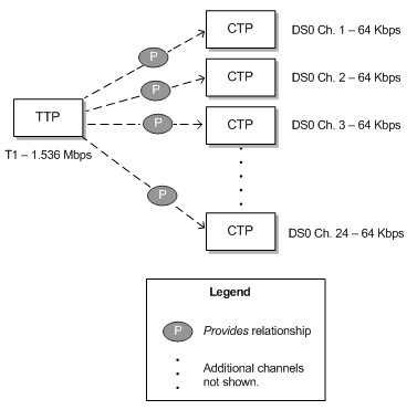
Simple signal structures have a hierarchy with only two levels: the TTP and one level of CTPs. For example, a T1 signal structure comprises a TTP with a total capacity of 1.536 Mbps and 28 CTPs representing 64 Kbps DS0 channels. Figure 17-7 illustrates such a signal structure. Other examples include T3 with 28 DS1 channels and E1 with 30 DS0 voice channels.
To supply capacity, the TTP is mapped to the termination points of a pipe. The individual channels defined by the signal structure can then be used to supply capacity to pipes provided by the one associated with the TTP. See "Configuring and Implementing Pipe Termination" for information about mapping signal structures to pipe termination points.
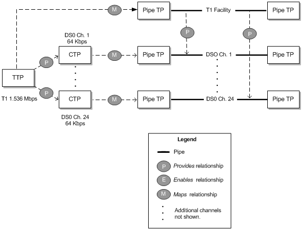
Figure 17-8 illustrates a simple signal structure mapped to pipes. Each of the 24 DS0 channels defined in the signal structure is mapped to a DS0 channel provided by the T1 facility to which the signal structure as a whole is mapped.
In UIM, if you create a T1 facility pipe entity with this signal structure, all of its DS0 channels will automatically be created at the same time. See "Defining Pipe Specifications" for information about creating pipes.
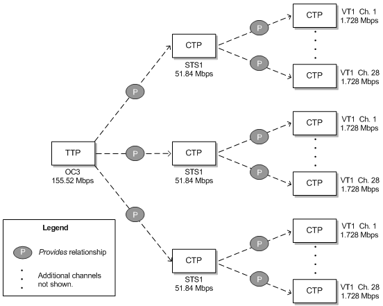
Complex signal structures are those that contain more than two levels. Examples include OC3, OC12, OC48, and STM1 structures. Figure 17-9 illustrates an OC3 signal structure.
The TTP represents the entire signal structure with 155.52 Mbps capacity. The OC3 is decomposed into two levels of channels. The first level comprises three STS1 channels, each with 51.84 Mbps. Each of the STS1 channels is further subdivided into 28 VT1 channels with 1.728 Mbps each. (The total of all of the VT1 channels' capacity is slightly less than the total C3 capacity of 155.52 Mbps because of some loss to overhead.)
In UIM, the hierarchy of CTPs in the signal structure dictates some rules about how the structure's capacity can be used:
-
After a channel pipe has been used to enable another pipe, higher-level channels in the structure no longer have their full capacity available. In other words, the parent channel cannot be used as a whole unit. For example, if you use one or more VT1 channels from an STS1 channel in an OC3 signal structure to enable a service trail, the STS1 channel as a whole is no longer available. Its remaining unused VT1 channels are available, however.
-
Child channels below a parent channel that is being used to enable a pipe are not available because their cumulative capacity has been used by the parent. For example, if you use an entire STS1 channel in an OC3 signal structure to enable a facility pipe, the individual VT1 channels in the STS1 are no longer available.
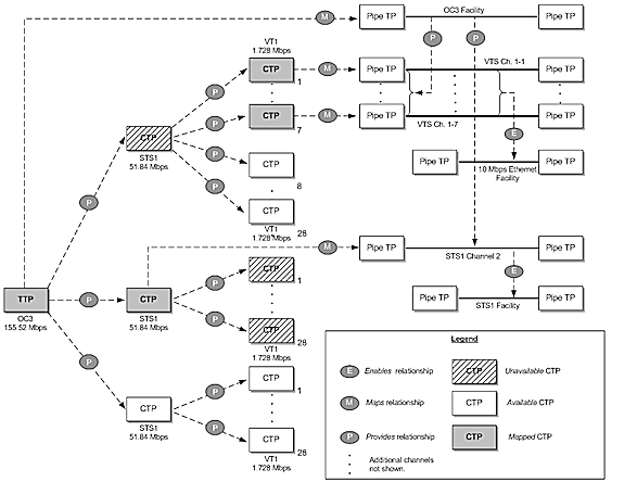
Figure 17-10 illustrates the OC3 signal structure from Figure 17-9 mapped to an OC3 facility pipe.
-
The TTP of the signal structure is mapped to the OC3 facility pipe itself.
-
The CTPs for the first seven VT1 channels in the first STS1 channel are mapped to seven VTS channels provided by the OC3 facility. These seven VTS channels are then used to enable an 18 Mbps Ethernet facility pipe.
Because some VT1 channels in this STS1 have been used, the STS1 as a whole is now unavailable. Its remaining VT1s can be used, however.
-
The CTP for the second STS1 channel in the signal structure is mapped to an STS1 channel provided by the OC3 facility. This channel in turn enables an STS1 facility pipe.
Because the STS1 channel in the signal structure is used as a whole, none of its VT1 channels is available for use.
Modeling Connectivity in Design Studio and UIM
You define specifications for connectivity entities in Design Studio and create entities based on those specifications in UIM. The following sections provide high-level information about designing and implementing connectivity entities. See the Design Studio Help and the UIM Help for detailed information about using the applications.
Defining Pipe Specifications
You define specifications for pipes in Design Studio. When you create a Pipe specification, you define several aspects of pipes based on the specification:
-
Pipe configurations and versioning. Configurations enable you to create versions of the pipe in which enablement and resource termination change over time. Pipe configurations and versioning are optional. See "Designing and Implementing Pipe Configurations" for more information.
-
Child pipes that can be provided by the pipe you are defining, such as cable-pair pipes provided by a cable. To define child pipes, you associate the specification of the child pipe to the parent pipe and specify minimum and maximum quantities. See "Configuring and Implementing Child Pipes for the Cable/Pair Model" for more information.
-
Pipe Termination Point specifications to apply to the pipe's termination points. Specifications for pipe termination points are optional. You use them only to associate characteristics or rulesets with them. You associate Pipe Termination Point specifications to Pipe specifications because their termination points are created automatically when the pipe is created. See "Configuring and Implementing Pipe Termination" for more information.
-
Characteristics that are appropriate for the specification. For example, to record technical details about a pipe, you can add one or more characteristics for that information. See the Design Studio Help for information about adding characteristics to specifications.
-
The pipe's capacity. You can define a pipe's capacity in one of two ways:
-
For non-TDM (packet) pipes, by associating Capacity Provided and Capacity Required specifications to the Pipe specifications. See "Configuring Pipe Capacity" for more information.
-
For TDM pipes, associating a Signal Termination Point specification and signal structure with the Pipe specification. See "Configuring Capacity with Signal Structures" for more information.
-
Different types of pipes include different combinations of these features; no single pipe includes all of the feature. There are three basic pipe models: cable/pair, packet facility, and TDM facility. Each model has a distinctive combination of features. See "Understanding Pipe Models" for more information.
See the Design Studio Help for more information about designing Pipe specifications.
Creating Pipe Entities in UIM
In UIM, when you create a Pipe entity based on a specification, the entity reflects the configuration choices you made in Design Studio. For example, if the Pipe specification includes child pipes, the minimum number will be created.
In UIM, you can associate a pipe entity with parties, roles, and other entities. For example, you can use role and party associations to record that a pipe is leased from another company, managed by a particular department, and used to support a specific customer. You can associate the following entity types with pipes:
-
Places
-
Roles
-
Involvements
-
Business interactions
-
Reservations
-
Inventory groups
-
Conditions
See the UIM Help for more information.
Understanding Pipe Models
UIM supports three different pipe models. The models are defined by how a pipe provides child pipes and by the way its capacity is structured. Path analysis and other processes are designed to support these models.
Note:
Connectivity models other than those described in this section are not supported by path analysis.Cable/Pair Model
In this model, a parent pipe represents a copper or fiber cable. This cable pipe provides child pipes that represent twisted pairs or fiber strands. Cable pipes are configured in the following way:
-
Minimum and maximum quantities for the child pipes are typically identical. As a result, all of them are created automatically when the parent pipe is created in UIM.
-
No capacity is provided or required. Because cables and cable pairs can be used only as whole units, no explicit definition of capacity is necessary.
-
No signal structure is present.
The cable and cable-pair pipes shown in Figure 17-3, "Pipe Relationships in a Local Loop Enablement", would be configured according to this model.
Packet Facility Model
This model supports Layer 2 links, such as ATM, Frame Relay, and Ethernet. Pipes based on this model provide capacity in bulk to pipes that they enable. An enabled pipe can consume the entire capacity or some smaller quantity depending on its requirements. The facility pipe can enable any number of pipes as long as its maximum capacity and usage percentage are not exceeded.
Packet facility pipes are configured in the following way:
-
No signal structure is defined.
-
The capacity required is the capacity that the pipe needs from another pipe for enablement.
-
The capacity provided is the total capacity provided by the facility pipe.
-
No child pipes are defined.
Figure 17-6, "Packet Capacity Example", illustrates a packet enablement scenario. The facility pipe would be configured according to this model.
TDM Facility Model
This model supports channelized technologies, such as TDM/PDH and SONET/SDH.
Note:
While you can use this pipe-based model to represent channelized connectivity, specialized capabilities are available when you use Channelized Connectivity entities. See Chapter 14, "Channelized Connectivity" for more information.In this model, facility pipes provide channels that enable service trails. A signal structure is associated to the facility pipe to define its capacity and channelization.
TDM facility pipes are configured in the following way:
-
The capacity required is the capacity that is required when enabled by another pipe.
-
The pipe includes a signal structure that defines the pipe's capacity provided and how its signal is channelized.
-
The capacity provided is not defined directly in the Pipe specification: it is inherited from the signal structure.
-
No child pipes are defined. Child pipes are unnecessary because the signal structure defines the channelization of the pipe's signal. Channels are created either automatically or as needed in UIM depending on how the signal structure is organized.
The following figures illustrate various scenarios that involve pipes based on the TDM facility model.
Designing and Implementing Pipe Configurations
Pipe configurations allow for versioning in pipe designs. You can use pipe configurations to record changes to a pipe's terminations and enablement over time. See "Configurations" for more information about entity configurations; see "Understanding Pipe Configurations" for more information about pipe configurations.
Defining Pipe Configuration Specifications
You define Pipe Configuration specifications and associate them to Pipe specifications in Design Studio. When you create an entity based on the Pipe specification in UIM, you specify that it is versioned to make possible the creation of pipe configuration versions. See "Implementing Pipe Configurations in UIM" for more information.
When you design a Pipe Configuration specification, you can add the following configuration items:
-
Termination. Limits the types of resources on which the pipe can be terminated. You can choose different resources for originating and terminating termination.
-
Transport. Limits the types of pipes that can enable the pipe.
-
Intermediate Node. Specifies a device or piece of equipment that must be in the connectivity path that enables the pipe. If you specify an intermediate node, that node must be included in enablements whether they are done manually or automatically.
You can constrain the resources that can be used for the Termination, Transport, and Intermediate Node configuration items by specifying entity specifications as specification options. The resources available for termination, transport, and intermediate nodes are limited to entities based on the selected specifications. If you do not add a configuration item or do not select an entity specification for a configuration item, any entity of the supported types (such as pipes for the Transport configuration item) is allowed.
The specification options in a configuration specification are enforced when you configure enablement or resource assignment. They also apply during automatic enablement using path analysis.
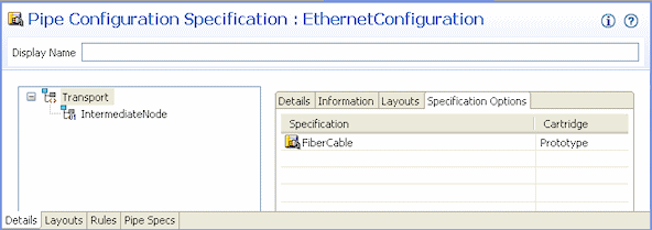
Figure 17-11 shows a Pipe Configuration specification for an Ethernet service trail pipe. A Transport configuration item has been added, with a specification option that defines that only entities based on the FiberCable specification can enable the pipe. An Intermediate Node configuration item has also been included.
Implementing Pipe Configurations in UIM
When you create a pipe in UIM based on a specification that is associated with a Pipe Configuration specification, you can choose to version the pipe. (You can also configure a pipe to be versioned after you create it, as long as no resources have been assigned to it.)
When you add a pipe configuration, the resource assignments you make to terminate the pipe and the pipes you select to enable it (either manually or through path analysis) are captured as part of the configuration. The configuration becomes effective when it is transitioned into Completed state. See Chapter 4, "Life Cycles and Statuses", for more information about life cycles and statuses.
For versioned pipes, you perform manual enablement or automatic enablement (path analysis) from the Summary page of the pipe configuration. Each version of the pipe configuration design can have a different enablement; a redesign with different enablement is often the reason for creating a new version.
After a configuration version has been completed or canceled, you cannot change its enablement. You must create a new configuration version for the updated enablement. You use the Pipe Configuration Enablement section in the Pipe Configuration page to specify the pipes that enable the parent pipe of the configuration.
See "Enabling Pipes" and the UIM Help for more information about enablement.
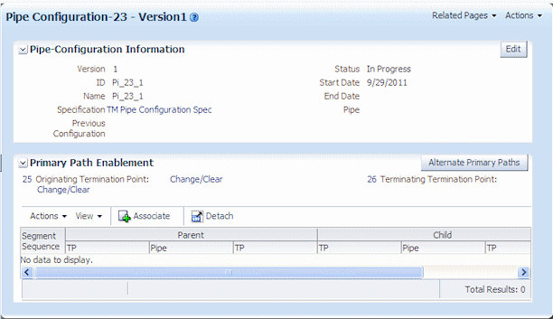
Figure 17-12 shows the Summary page for a pipe configuration. You use the Pipe Configuration Enablement section of the page for manual enablement.
Configuring and Implementing Pipe Termination
You can associate Pipe Termination Point specifications to Pipe specifications when you design a pipe in Design Studio. Pipe Termination Point specifications are necessary only to add characteristics to capture specific information about the termination point, to associate rulesets to the termination points, or to limit the types of resources with which the termination points can be associated. If you do not associate a Pipe Termination Point specification with the Pipe specification, the pipe's termination points are created without specification in UIM.
See the Design Studio Help for more information about creating Pipe Termination Point specifications and associating them with Pipe specifications.
In UIM, you associate pipe termination points to entities in the inventory to describe where the pipe terminates. You can associate the following kinds of resources to pipe termination points:
-
Connector
-
Device interface
-
Equipment
-
Logical device
-
Network
-
Physical Device
-
Port
If the pipe termination points were created with a specification, it may limit the type of resources on which the pipe can terminate. For, example, a Pipe Termination specification may limit pipe termination to entities based on a particular Device Interface specification.
The resources that a pipe terminates on are assigned to the pipe and are not available to be consumed by other services, sites, or resources unless its specification indicates that it can be assigned to multiple entities. See "Consumption" for more information about shared consumption.
When pipe termination points are terminated on entities that have place associations, UIM includes the pipe in the inventory topology. See "Topology" for more information.
Figure 17-13 shows information about the termination points in a UIM Pipe Summary page. The termination points were created without specification.
Figure 17-13 Pipe Termination Points in UIM
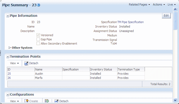
Description of ''Figure 17-13 Pipe Termination Points in UIM''
See the UIM Help for more information about managing pipe termination in UIM.
Configuring and Implementing Child Pipes for the Cable/Pair Model
When you design a cable pipe based on the Cable/Pair model in Design Studio, you specify which Pipe specification should be used for its child pipes. You also specify the minimum and maximum number of child pipes.
For example, if you are designing a specification for a 25-pair copper cable, you include the specification for the cable-pair pipes that the cable provides. You specify a minimum number of cable pairs that will be created automatically when you create an entity based on the cable specification in UIM. You also specify the maximum number of cable pairs that the cable can provide. In most cases, you set the minimum and maximum to the same value to ensure that all the cable pairs are created when the parent pipe is created.
See the Design Studio Help for information about designing parent and child Pipe specifications.
After you create a parent pipe and its minimum number of child pipes in UIM, you can add additional child pipes if the maximum number has not been reached. After additional child pipes have been added, you can delete them until the minimum is reached.
You can view a parent pipe's hierarchy of child pipes in the Pipe Hierarchy section of a Pipe Summary page. Each child pipe is shown along with the identity, inventory status, and assignment status of pipes it enables.
See the UIM Help for more information about managing child pipes in UIM.
About Pipe Termination and Rate Codes
Although rate codes apply primarily to channelized connectivity, they are also relevant when you terminate pipe connectivity. (See "About Rate Codes" for information about rate codes in general.)
When you terminate a pipe that has bit rate capacity on a device interface that has a rate code, UIM validates the pipe's capacity against the device interface's rate code. (UIM validates against the pipe's capacity required first. If no capacity required value exists, UIM validates against the capacity provided.) If the pipe's capacity matches the bit rate of the device interface's rate code, UIM allows the termination.
You can define a capacity variance that specifies how much the capacity can vary from the rate code and still be validated successfully. The variance is a percentage that you specify with the connectivity.capacityVariant parameter in the system-config.properties file. See UIM System Administrator's Guide for more information about setting configuration parameters.
Setting a capacity variance is particularly useful when you have upgraded from a previous version of UIM. In this situation, you may have existing pipe capacity defined with bit rates that do not exactly match the rate code bit rates due to rounding.
Configuring Pipe Capacity
Pipes provide and require capacity in the form of bandwidth. You can define pipe capacity for Pipe specifications in Design Studio in two different ways:
-
By associating Capacity Provided and Capacity Required specifications to Pipe specifications. You use this method of defining capacity for pipes based on the packet facility model. (See "Packet Facility Model" for more information.) For example, you use Capacity Provided and Capacity Required specifications for pipes that represent packet-switched Layer 2 connectivity, such as Frame Relay and Ethernet. See "Configuring Capacity for Packet Facility Pipes" for more information.
-
By associating signal structures to Pipe specifications. The signal structures define how the signal is channelized and include a reference to a Capacity Provided specification. You use signal structures for pipes based on the TDM Facility model. (See "TDM Facility Model" for more information.) For example, you use signal structures to define capacity for an OC3 pipe that includes STS1 and VT1 channels. See "Configuring Capacity with Signal Structures" for more information.
You do not define capacity for pipes based on the Cable/Pair model. Cable pairs offer themselves as a whole for enablements. Their capacity can be consumed only as a unit, so there is no need to specify the amount. See "Cable/Pair Model" for more information about pipes based on this model.
Configuring Capacity for Packet Facility Pipes
Capacity for packet-based connectivity is defined using the standard UIM capacity capabilities. See "Capacity" for more information.
When you define a specification for a packet-based pipe in Design Studio, you associate it with Capacity Provided and Capacity Required specifications that define the pipe's capacity. A pipe can enable other pipes up to the maximum capacity and consumable percentage defined by the Capacity Provided specification with which it is associated. To be enabled, a pipe requires the capacity defined in the Capacity Required specification with which it is associated.
Defining Capacity Required specifications is similar, but no consumable percentage is involved. See the Design Studio Help for more information.
In UIM, when you create an entity based on a specification that includes a relation to a Capacity Provided or Capacity Required entity specification, the relevant capacity is automatically associated to the entity. UIM automatically keeps track of capacity usage. You are prevented from making enablements that exceed a pipe's maximum capacity provided.
Configuring Capacity with Signal Structures
You use signal structures to define capacity for pipes based on the TDM model. (Channelized Connectivity entities define their signal structures by using the UIM signal architecture. See "About the UIM Signal Architecture" for more information.)
The signal structure defines how a pipe's signal is channelized. The signal structure includes an association to a Capacity Provided specification, meaning that no such association is required for the pipe itself.
To define signal structures and associate them with Pipe specifications, you create hierarchies of Signal Termination Point specifications in Design Studio. The parent-child relationships among the Signal Termination Point specifications determine the organization of the signal structure.
The hierarchy includes one parent specification to represent the top signal structure as a whole, along with one or more layers of child specifications. This organization of Signal Termination Point specifications corresponds to the hierarchy of TTPs and CTPs. See "Understanding Signal Structures" for more information.
For example, if you are creating a signal structure comprising a T3 parent signal termination point and 28 T1 child termination points, you must create a T3 Signal Termination Point specification and a T1 Signal Termination Point specification.
When you design a child Signal Termination Point specification, you define the capacity unit amount, unit of measure, and number of child signals. (See "Defining and Measuring Capacity" for more information about units of measure.) In a T3 scenario, there is only one layer of child signals, so the number of child signals is set to zero for the child Signal Termination Point specification. If there were more layers to the signal structure, you would specify the number of child signals below this one in the hierarchy.
You define the total bandwidth for the signal structure by relating a Capacity Provided specification to the highest-level Signal Termination Point specification in the structure. You also enter the number of child signals in the first layer of the structure and select the Signal Termination Point specification for that layer. For example, for the T3 structure mentioned previously, you would specify 28 child signals and select the T1 Signal Termination Point specification.
When you define a Signal Termination Point specification, you can include compatible capacities and units of measure supported by the signal structure. Using this feature, you can specify that a signal structure can support not only signals of exactly matching capacity but also signals of lesser capacity. For example, you can specify that a SONET STS1 channel with a bit rate of 51.840 Mbps can support an STS transmission facility of 51.840 Mbps capacity or a DS3 facility at a rate of 44.736 Mbps. See the Design Studio Help for more information about configuring Signal Termination Point specifications for compatible signals.
You can associate a Signal Termination Point specification with a Pipe specification in Design Studio. When a pipe entity is created in UIM based on a specification with such an association, the signal structure is created automatically at the same time. The channels defined in the signal structure are created immediately for simple signal structures (those with only one layer of child signals) and as needed for enablement in complex signal structures.
See the Design Studio Help for more information about how you design Signal Termination Point specifications.
In UIM, you can manually associate a signal structure with a pipe that does not already have one. When you make the association, the channels are created under the same rules used for signal structures associated by the specification.
See the UIM Help for more information about associating signal structures with pipes.
Viewing Signal Structure Information in UIM
There are several ways in UIM to view information about a pipe's signal structure:
-
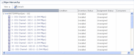
Figure 17-14 shows how the Pipe Hierarchy section of the Pipe Summary page displays the channel hierarchy defined by the signal structure. Each channel is shown along with the identity, inventory status, and assignment status of pipes it enables.
-
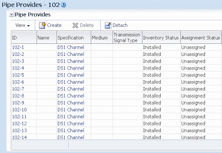
Figure 17-15 shows how the Pipe Provides page lists all the child pipes that have been created based on the signal structure.
-
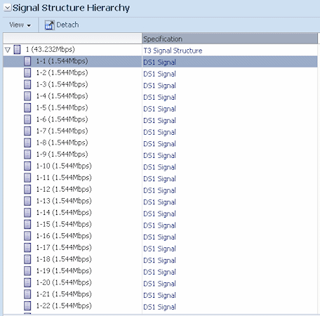
Figure 17-16 shows how the Signal Structure page displays all the channels defined by the signal structure, even if they have not yet been created in inventory.
See the UIM Help for more information about viewing signal structure information for pipes.
Changing the Capacity of Existing Pipes
You can change the capacity provided or capacity required after you create a pipe in UIM. It is unusual to make such a change, but it may be necessary under some circumstances. For example, you may need to change the capacity of fractional T1 or E1 pipes with capacities of 256, 384, 512 and 768 Kbps.
The following rules apply to changing the capacity provided amount.
-
You cannot change the capacity provided information if the pipe has a signal structure because the signal structure defines capacity provided.
-
If a pipe is not enabling any other pipes (has no capacity consumed), you can increase or decrease the total capacity provided.
-
If a pipe is enabling another pipe (has some capacity consumed), you cannot decrease its capacity provided; you can only increase it.
The total capacity provided amount factors in the consumable percent value. For example, if you have a pipe that provides 10 Mbps with 100% consumable, you could not change its capacity provided to 10 Mbps with 75% consumable if the pipe is enabling another pipe.
There are no rules about changing the capacity required amount. You can increase the capacity required after a pipe has been enabled by another pipe, even if you increase it to more than the capacity available on the enabling pipe. Changing the capacity required on a pipe that is already enabled by another pipe does not change the amount of capacity consumed on the enabling pipe.
See the UIM Help for more information about changing capacity in UIM.
Enabling Pipes
You enable a pipe to define how its connectivity is implemented. For example, a POTS service trail represents the connectivity from a voice switch in a central office to the subscriber terminal. This service trail is enabled by several different pipes, including cable pairs between the MDF to a cross-connect terminal and from the cross-connect terminal to the subscriber terminal. See "Enables Relationships" for conceptual information about pipe enablement.
In UIM, you can enable pipes in two ways:
-
You can manually configure the enablement, which involves specifying the pipes that comprise the connectivity path. UIM automatically creates cross-connects to bridge gaps between pipes. See "Enabling Pipes Manually" for more information.
-
You can have UIM automatically configure the enablement using path analysis. Path analysis calculates a least-number-of-hops path between two points that you specify. See "Enabling Pipes Automatically with Path Analysis" for more information.
Enabling Pipes Manually
When you manually enable a pipe, you select the pipes that comprise the enabling connectivity path. For example, in a POTS scenario, you select cable pairs that connect the MDF to a cross-connect terminal block and the terminal block to the subscriber terminal.
When you manually configure enablement, UIM automatically creates cross-connects or connectivity gaps to ensure that there is a continuous path from the originating termination point to the terminating termination point. A connectivity gap or cross-connect is required when the enabling pipes you specify do not share a common termination point. See "About Connectivity Gaps in Pipe Enablement" for more information.
In the POTS scenario mentioned above, for example, UIM automatically creates a cross-connect to represent the jumper on the cross-connect terminal block that connects the two cable pairs.
The way you manually enable pipes varies slightly depending on whether the pipe is versioned or not. See the UIM Help for more information about enabling pipes manually.
Enabling Pipes Automatically with Path Analysis
Path analysis is an automated process in UIM that helps you locate and assign pipes for enablement. You specify the starting point (the source), the ending point (the target), and a variety of optional criteria, including capacity requirements. Path analysis evaluates possible paths based on the criteria you provide and returns paths from which you can select.
For example, to enable a DS1 service trail from Dallas to Orlando, you can use path analysis to find the available paths between those points.
Path analysis uses the inventory topology to find paths. The paths it locates are those that are defined by the UIM topology framework. See "Topology" for more information.
You can specify any entity that is included in the UIM topology as a source or target for path analysis. By default, the following entity types are included in the topology:
-
Equipment
-
Logical devices
-
Networks
-
Network nodes
-
Physical devices
-
Places (site and location only)
-
Property locations
Path analysis identifies paths by finding pipe termination points that are associated with the source and target you specify. For example, if you specify a logical device as the source, path analysis looks for pipes with termination points that are associated with that logical device. Similarly, if you specify a Place entity such as Santa Clara or Austin as the target, path analysis looks for pipes with termination points on entities associated with that place.
To find a path, path analysis must be able to find pipes whose termination points are associated with devices in common. For example, suppose that Pipe X is terminated on Device Interface A of Logical Device 1 and Device Interface B of Logical Device 2 and that Pipe Y is terminated on Device Interface C of Logical Device 2 and Device Interface D of Logical Device 3. (See Figure 17-17.) In this case, path analysis can find a path between Logical Device 1 and Logical Device 3.
The following list includes some points about the way path analysis that you should keep in mind when you enable a pipe automatically:
-
Because path analysis uses connectivity as it is defined by topology, it cannot find paths on pipes that are terminated directly on places. It is possible to terminate a pipe in this way, but the topology framework does not create a topology edge for such an arrangement.
To terminate a pipe on a place and use the pipe for enablement, you must create a dummy device on which to terminate the pipe. You can then associate that device with the desired place. This technique is especially useful when you want to represent connectivity or traffic flow to a place, but do not know or care about the details. For example, you may want to include connectivity to a third-party network about which you have little information. In this situation, you can create a dummy device at the desired place.
-
Path analysis can find paths between network nodes by looking for edges that connect them. Paths between network nodes cannot be used to actually enable pipes, however. They represent logical rather than actual connectivity.
-
If you are searching for paths between entities that have a hierarchical structure, such as logical devices, physical devices, or equipment, you should use the highest-level entities for the source and target. For example, to find a path starting from a port, you should consider the hierarchy in which it is included. In this case, the port is assigned to a card, which is in turn assigned to a shelf. You should use the shelf (an Equipment entity) as the starting point for path analysis.
-
Path analysis is designed to work with the three supported pipe models: cable/pair, packet facility, and TDM facility. See "Understanding Pipe Models" for more information.
About Path Analysis Criteria
When you perform path analysis, you specify criteria in the Path Analysis Search page to find paths. These criteria determine how path analysis goes about finding connectivity paths.
The following list provides introductory information about the criteria you can enter. See the UIM Help for detailed information about the criteria and for step-by-step instructions about running a path analysis.
-
The only required criteria for a path analysis are the source and target types and IDs. You can enter IDs directly or search for them.
-
You can specify an intermediate node that must be included in the path.
For example, if you need a pipe to connect a subscriber terminal and a switch, path analysis can specify that the path must include a DSLAM by adding it as an intermediate node.
-
You can specify the capacity required from the enabling pipe by entering a bit rate and unit of measure. For example, if you are enabling a pipe that requires 1.544 Mbps of capacity, you can specify a bit rate of 1.544 and Mbps as the unit of measure. If the pipe to be enabled is already associated with a Capacity Required specification, the bit rate and unit of measure are automatically selected.
-
In cases where fractional capacity is required, you can include a quantity along with the bit rate and unit of measure. For example, to enable a 256 Kbps service trail, you can enter a quantity of 4 and enter a bit rate of 64 Kbps to enable the service trail over four 64-Kbps channels.
-
You can specify that path analysis take pipe directionality into account. By default, path analysis treats pipes as bi-directional, but you can override that in cases where directionality is important. See "Understanding Pipe Directionality" for more information.
-
You can choose to include partial paths in the path analysis results. Partial paths are those that are not currently continuous from source to target. By default, only continuous paths between source and target are returned.
-
You can choose to include network nodes and edges in the path analysis. Network nodes and edges provide no connectivity, so they cannot be used for enablement. Including network nodes and edges can help in identifying the best routes, however.
Note:
You must use this option if you specified a network or network node as the source or target. -
You can tune path analysis to control the number of paths returned. The default is to search for the most direct paths, but you can choose to include more paths. Processing time increases as you include more paths.
-
You can choose to include secondary paths in the path analysis if a pipe is configured for multiple enablement. Selecting this option means that path analysis results will include primary paths and the ability to select matching secondary paths. See "About Multiple Enablement" for more information.
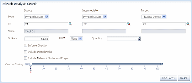
Figure 17-18 shows a Path Analysis Search page with criteria entered.
In addition to the criteria that you enter, the path analysis can also include filtering criteria defined in rulesets associated with the specification of the pipe you are enabling. For example, results may be limited to include only pipes that are based on a particular specification or that include certain text in their names. A sample cartridge is supplied with UIM to provide examples of this capability. See UIM Developer's Guide for information about customizing path analysis.
Path analysis results are also limited if the pipe that you are enabling has a Pipe configuration in which a Pipe specification is assigned to the Transport configuration item. In this case, path analysis results include only pipes based on that specification. See "Defining Pipe Configuration Specifications" for more information.
About Path Analysis Results
The results of a path analysis are displayed in the Available Paths page. Each path found between the source and target is shown as a group of rows, with each row representing a segment of the path. The ID in the From ID column of the first row of the path represents the source you entered, and the ID in the To ID column of the last row in the path represents the target.
If the pipe you are enabling is configured for multiple enablement and you want to include secondary paths, the results include both primary paths and the ability to select secondary paths. The primary and secondary paths are displayed in separate tables.
You can open a visualization of the path in the network topology. See the UIM Help for instructions about using UIM topology features.
Figure 17-19 shows search results for the criteria entered in Figure 17-18. In this case, only one path was found. If there were additional paths that met the criteria, they would be listed in rows below the first path.
Understanding Path Analysis Modes
Path analysis can operate in two different modes. The way you run a path analysis is the same in both modes, but the mode affects which paths are returned and the amount of processing required.
-
In Complex mode (the default), path analysis considers all possible paths between the source and target, which means evaluating a large number of permutations. You can use rulesets to limit the amount of data to be processed. This mode of path analysis is suitable for complex networks with many possible connections.
-
In Simple Linear mode, path analysis works by iteratively analyzing paths working from the end points toward a common node. This mode of analysis is suited to paths that are inherently linear and have 10 or fewer hops. For example, Simple Linear analysis is suitable for POTS scenarios. The Simple Linear algorithm is less processor-intensive than the Complex algorithm.
The analysis mode can be set for UIM as a whole or for specific Pipe specifications. See UIM Developer's Guide for more information.
Viewing Enablement Information
After you have enabled a pipe, you can view enablement information in two ways:
-
The Pipe Enabled By page lists enabling pipes, including automatically created cross-connects and connectivity gaps. (The Pipe Configuration page shows the information for versioned pipes.)
The list includes columns for the sort order, parent pipe information, child pipe information, and assignment status. The parent and child pipe and termination point information enables you to see information about all pipes involved in the enablement, including their parents.
-
The Enabled By Visualization page displays the enablement visually. See "Viewing a Pipe Enablement Visualization" for more information.
Viewing a Pipe Enablement Visualization
The enablement visualization of a pipe or pipe configuration shows schematic views of the trail pipe in the upper part of the canvas and the enabling pipes in the lower part. When a pipe is enabled by more than one connectivity path, such as in a SONET/SDH network, both paths are displayed.
The visualization includes the following:
-
Pipes. Pipes are labeled with their IDs and names and the names of their parent pipes (if any). For example, if the second channel pipe of Facility Pipe LS_BW_A is included in the enablement, it would be labeled LS_BW_A (LS_BW_A-2) in the schematic view.
-
Connectivity Gaps and Cross-Connects. If connectivity gaps or cross-connects were created during the enablement, they are shown as thin lines connecting the thicker lines that represent other pipes.
-
Pipe termination points. If the termination points are not terminated on a resource, they are labeled with their IDs. If they are terminated on a resource, they are labeled with the ID and name of the resource or its parent. For example, if a termination point is terminated on a device interface, the visualization displays the name and ID of the logical device that holds the interface. Boxes representing parent resources surround the termination points. If two termination points are terminated on the same parent resource, they are displayed in the same box.
You can expand termination points in the visualization to view their resource terminations. You can expand individual termination points or all termination points simultaneously.
Figure 17-20 shows a simple enablement in which a service trail is enabled by a connectivity path comprising three pipes that are terminated on logical devices in four locations. Cross-connects have been added on the logical devices that have two pipe termination points.
