3 Design Studio Overview
This chapter provides introductory information about how Oracle Communications Design Studio is used with Oracle Communications Unified Inventory Management (UIM).
Design Studio is a separately licensed product that you install independently of UIM. For detailed information on how to install Design Studio, see Design Studio Installation Guide.
About Design Studio
Design Studio is an Eclipse-based development environment that supports several Oracle Communications applications in addition to UIM. For UIM development, you must install the Design Studio Platform, Design Studio Domain Modeling, and Design Studio for Inventory plug-ins.
You use Design Studio to define artifacts such as specifications and rulesets that you later deploy into UIM. You can define the following kinds of artifacts in Design Studio:
-
Entity specifications
-
Data elements tagged as characteristics
-
Units of measure and measurement types
-
Capacity provided, capacity required, and capacity type specifications
-
Entity identification specifications
-
Rulesets
-
Extension points and enabled extension points
-
Ruleset extension points and global ruleset extension points
-
Sequence specifications
See the Design Studio Help for detailed information about how you work with each of these types of artifacts.
About Projects and Cartridges
In Design Studio, you create projects to contain the artifacts that you define. Each project corresponds to a collection of files and folders where data is stored. When a project is complete, you use Design Studio to build a cartridge that you deploy into UIM.
See the Design Studio Help for information about deploying cartridges interactively from Design Studio. See the Design Studio Developer's Guide for information about automating cartridge deployment using the Design Studio Cartridge Management Tool (CMT). See the UIM Cartridge Guide for more information about the Cartridge Deployer Tool (CDT).
Note:
You must install two required projects in Design Studio before you can create UIM projects and deploy them as cartridges. The following two projects must be open in your workspace:-
ora_uim_model is a read-only project that represents the UIM model. It supports the ability to define specifications and characteristics and is also used to validate which entity types can be assigned or referenced by configuration items.
-
ora_uim_mds is a read-only project that represents the fields that can be displayed in UIM entities. This project makes it possible to define the layout of fields in entities.
See UIM Installation Guide and Design Studio Help for more information about importing these projects.
You can also use Design Studio to open, view, and deploy content supplied by Oracle. For example, you can open the cartridges in an Oracle sample cartridge pack, add cartridges required for your business, and then deploy the cartridges into UIM.
See UIM Cartridge Guide for information about upgrading and extending cartridges.
Understanding the Design Studio Workbench
The Design Studio Workbench is the environment you use to develop and maintain specifications, rulesets, and other artifacts. The contents of the Workbench depend on the perspective that is currently displayed.
Perspectives are arrangements of content optimized for particular purposes. Design Studio includes several predefined perspectives. The two most commonly used perspectives are:
-
The Studio Design perspective, which provides tools for designing and maintaining specifications and other artifacts.
-
The Studio Environment perspective, which includes views for working with and deploying cartridges.
When you start Design Studio the first time, the Workbench displays a default perspective. After that, Design Studio starts up in the last perspective used.
About Views
The tools in the Workbench are smaller, window-like areas called views. Each perspective has a different set of views and each view is designed for a particular purpose.
For example, the Studio Design perspective includes the following views:
-
Projects: This view shows the project contents grouped alphabetically by specification type.
-
Relation: This view shows parent and child relationships for the selected specification.
-
Relation Graph: This view shows a graphical view of a specification's relationships.
-
Data Element: This view shows all the entities in the project that include data elements.
-
Problems: This view displays information about problems in the cartridge, such as build errors.
The Studio Design perspective also includes editors, windows in which you do the actual work of designing and modifying specifications and other artifacts. When you make a selection in the Studio Projects view or Dictionary view, an editor for the selected artifact opens. See "About Editors" for more information about editors.
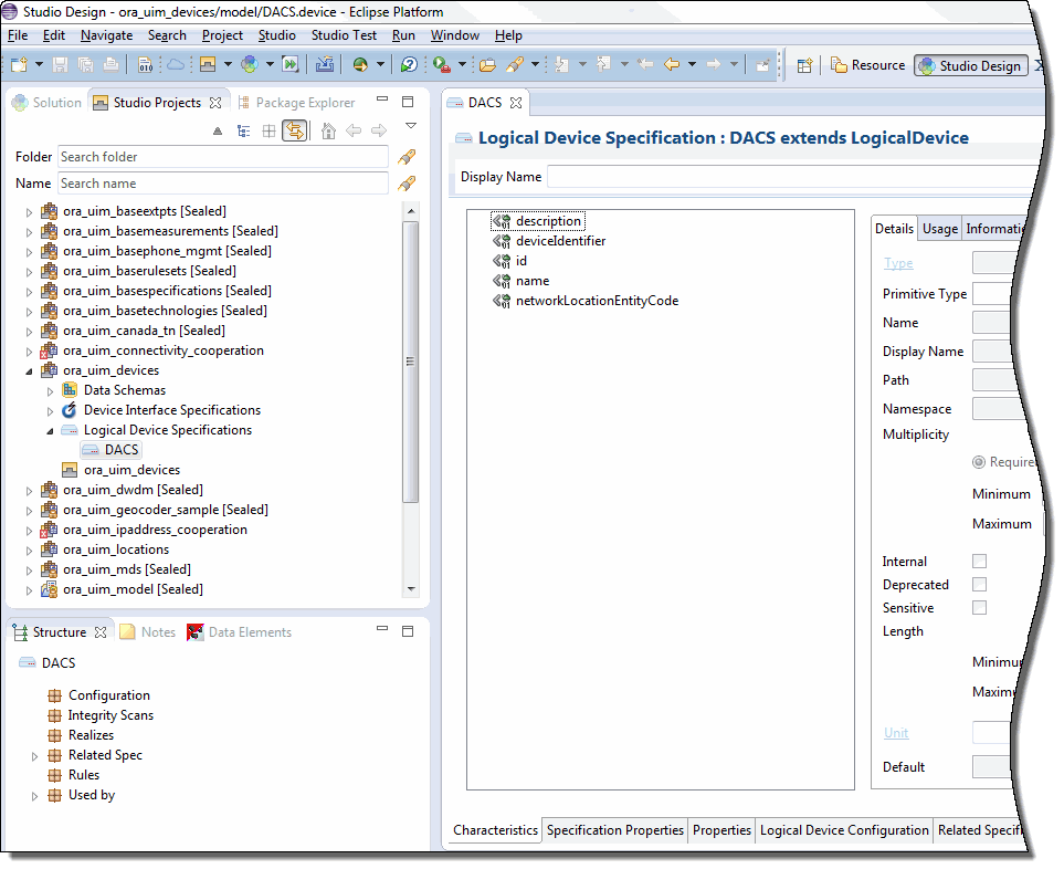
Figure 3-1 displays the Workbench with the Studio Design perspective. In this window, the Studio Projects, Package Explorer, and Solution views are open with the Studio Projects view activated. A Logical Device specification is selected in the Studio Projects view, making the corresponding Logical Device Specification editor active.
See ”Workbench User Guide” in Eclipse Help for additional information about views and editors.
About Editors
Editors are the tools you use to design specifications and other artifacts in Design Studio. Each editor is tailored for a particular type of artifact. Editors are opened based on selections you make in views. Although multiple editors can be open simultaneously, only one is active at a time.
Editors are divided into tabs arranged across the bottom. Some tabs appear in most editors, but others pertain only to a few.
The editors for the various types of entity specifications vary based on the nature of the entity, but many contain the following tabs:
-
Specification Properties: Defines basic information about the specification, such as whether the IDs of entities defined by the specification are generated automatically or manually. See "Entity Identification" for more information about IDs.
-
Characteristics: Defines characteristics associated with the specification. Using characteristics enables you to store information in addition to the default data elements for the entity. For example, you can add characteristics to store vendor-specific information about Equipment entities. See "Characteristic Labels" for more information.
-
Related Specifications: Enables you to define relationships between specifications. See "Understanding Specification Relationships" for more information about relating specifications.
-
Configuration Spec Usage: Enables you to indicate that an entity based on this specification can be consumed or referenced in the configuration specifications listed in the tab.
-
Rules: Associates entity specifications with rulesets that customize UIM behavior. For detailed information and procedures about using extension points and rulesets, see UIM Developer's Guide.
-
Layouts: Defines how entities based on the specification appear in UIM.
-
Media: Defines media files (such as JPG or GIF files) that can be associated with a specification for display in UIM.
There are additional tabs used with some specifications. In this guide, those tabs are explained when they are used with a particular specification type.
Designing Entity Specifications
Much of the work you do in Design Studio will likely be designing entity specifications. The entity specifications you design in Design Studio are blueprints for the entities you create in UIM to model your inventory.
Understanding Specification Relationships
One of the most important parts of designing a specification is defining relationships to other specifications. For example, if you design a Logical Device specification, you can build in a relationship to a Device Interface specification that ensures that a particular number of interfaces are created automatically when you create a logical device in UIM.
Note:
Design Studio enables you to define relationships from any specification to any other specification, but only a limited number of these relationships are recognized by default in UIM. The nature and results of recognized relationships vary depending on the specifications involved. See Table 3-1 for more information.Related specifications frequently result in provides and constrains relationships among entities in UIM. For example, when you relate a Logical Device specification to a Device Interface specification, you establish a provides relationship in UIM between Logical Device entities based on the specification and Device Interface entities based on the related specification. If you design a Logical Device specification for an ATM switch and relate it to an OC-12 Device Interface specification, when you create an ATM switch entity in UIM, OC-12 device interface entities are created automatically. The number of device interfaces created depends on a minimum value that you set for the relationship in the Logical Device specification. A maximum value for the relationship limits the number of child entities that can be added.
You can customize UIM by using extension points and rulesets so that the relationships not recognized by default in UIM are meaningful. For example, you can add rulesets that automatically create child entities based on a related specification when an entity is created based on a parent specification. See UIM Developer's Guide for more information.
A constrains relationship results from relating a Network Node specification to a Logical Device specification. This relationship limits the types of entities that a network node can represent in UIM. For example, if you design a Network Node specification that includes a relationship to a DSLAM Logical Device specification, you can associate network node entities based on the specification only to entities based on the DSLAM specification.
You establish most relationships in Design Studio from a specification editor's Related Specs tab. Certain types of relationships are handled on different tabs, however. For entities that can have configurations, for example, you define entity-to-configuration relationships on the Configurations tab.
Table 3-1 shows the specification relationships in Design Studio that are supported by default in UIM.
Table 3-1 Specification Relationships
| Specification | Related Specifications | Usage | Minimum and Maximum |
|---|---|---|---|
|
Device Interface |
Device Interface |
UIM creates the sub-interfaces provided by a new device interface entity based on these relationships. |
The minimum value on the relationship determines the number of device interface entities that UIM creates and is the minimum number that must be maintained on the device. The maximum value constrains the number of device interface entities that can be subsequently created. |
|
Equipment |
Equipment Holder Physical Port Physical Connector |
UIM creates the equipment holders, physical ports, and physical connectors provided by a new equipment entity based on these relationships. |
The minimum value determines the number of equipment holder, physical port, and physical connector entities that UIM creates and it constrains the user from deleting the physical ports and physical connectors after the equipment is created. The maximum value is not used for equipment holder because the number of holders is set by the specification and cannot be changed after an entity has been created. The maximum value is used for ports and connectors and constrains the number of ports and connectors entities that can be subsequently created. |
|
Inventory Group |
Inventory Group |
UIM constrains the types of inventory groups that can be related as parent and child inventory groups. |
Not applicable. |
|
Custom Network Address Custom Object Equipment Logical Device Logical Device Account Party Physical Device Pipe Pipe Termination Point Product Service Telephone Number |
Inventory Group |
UIM constrains the entity to participate only in inventory groups created from the related inventory group specifications. |
Not applicable. |
|
Logical Device |
Device Interface |
UIM creates the device interfaces provided by a new logical device entity based on these relationships. |
The minimum value on the relationship determines the number of device interface entities that UIM creates and is the minimum number that must be maintained on the logical device. The maximum value constrains the number of device interfaces that can be subsequently created. |
|
Logical Device |
Logical Device Configuration |
UIM constrains the type of logical device configuration that can be created for a logical device. |
Not applicable. |
|
Network |
Network Node Network Edge |
UIM constrains the types of network nodes and network edges that can be included in a network. |
Not applicable. |
|
Network |
Network Configurations |
UIM constrains the type of network configuration that can be created for a network. |
Not applicable. |
|
Network Edge |
Pipe Custom Object |
UIM constrains the types of pipes and custom objects that can be represented by a network edge. |
Not applicable. |
|
Network Node |
Custom Network Address Custom Object Device Interface Equipment Logical Device Network Physical Device Physical Port |
UIM constrains the types of entities that can be represented by a network node. Party and Place associations to Network Node are not currently constrained by specification relationships. |
Not applicable. |
|
Physical Device |
Physical Port Physical Connector |
UIM creates the physical ports and connectors provided by a new physical device entity based on these relationships. |
The minimum value on the relationship determines the number of port or connector entities that UIM creates and is the minimum number that must be maintained on the device. The maximum value constrains the number of port and connector entities that can be subsequently created. |
|
Pipe |
Pipe Pipe Termination Point |
UIM creates child pipes (cable pairs) or pipe termination points provided by a new pipe entity based on this relationship. See UIM Information Model Reference for more detailed information about relating pipe specifications to pipe termination point specifications. |
The minimum value on the relationship determines the number of child pipe entities that UIM automatically creates and is the minimum number that must be maintained on the pipe. The maximum value constrains the number of child pipe entities that can be subsequently created. Two pipe termination points are created for all pipe entities; however, if a pipe termination point specification is associated with a pipe, the pipe creates a pipe termination point using the related pipe termination point specification. |
|
Pipe |
Capacity Provided |
UIM creates a capacity provided for the pipe based on this relationship when there is not a signal termination point specification related to the pipe. If a signal termination point specification is associated with the pipe specification, the capacity provided is created based on the capacity provided specification on the signal termination point specifications. |
Not applicable. |
|
Pipe |
Capacity Required |
UIM creates a capacity required for the pipe based on this relationship. |
Not applicable. |
|
Pipe |
Signal Termination Point |
UIM creates a signal structure for the pipe based on this relationship. |
Not applicable. |
|
Pipe |
Pipe Configurations |
UIM constrains the type of pipe configuration that can be created for a pipe. |
Not applicable. |
|
Place |
Place Configurations |
UIM constrains the type of place configuration that can be created for a geographic site. |
Not applicable. |
|
Product |
Product Service |
UIM constrains the types of products and services than can be added to a product in the product hierarchy. |
UIM validates the minimum and maximum values in the relationship against the minimum and maximum child products and services in the product hierarchy. |
|
Service |
Service Configurations |
UIM constrains the type of service configuration that can be created for a service |
Not applicable. |
|
Signal Termination Point |
Capacity Provided |
UIM creates a capacity provided for the signal structure based on this relationship. |
Not applicable. |
|
Signal Termination Point |
Signal Termination Point |
UIM creates child signal termination points in a signal structure based on this relationship. |
The minimum value dictates the number of provided connection termination points to be created when the parent trail termination point or connection termination point is created.The maximum value is not used.UIM does not support creating or deleting connection termination points after the signal structure has been created. |
Extending Specifications with Rulesets
You can use rulesets, extension points, and ruleset extension points to customize how UIM performs actions related to entities based on a specification.
-
An extension point defines when the customized behavior takes place, such as immediately after an entity based on the specification takes place or when the Validate command is selected from the Actions menu.
-
A ruleset defines what happens at the extension point. For example, you can write code that automatically creates additional entities or that validates that the entity is configured properly.
-
A ruleset extension point brings together a ruleset and an extension point into a unit that you add to the Rules tab of an entity specification.
For detailed information and procedures about extending specifications, see UIM Developer's Guide.
Working with Characteristics
Characteristics provide a means of storing specific items of information about an entity that are not present by default. For example, if you define a specification for a particular type of equipment, you can add characteristics that describe vendor-specific features of the equipment. When you create entities in UIM based on a specification that includes characteristics, those characteristics appear automatically in the entities.
From the point of view of Design Studio, characteristics are data elements. You tag these data elements as characteristics, which makes them available for use in entity specifications. See the Design Studio Help for more information about data elements.
In Design Studio, characteristics are displayed on the Characteristics tab of specification editors and are also included in the list of data elements visible in the Data Schema editor.
In UIM, characteristics appear as fields in which users enter or select information. Users can expand UIM search parameters to include characteristics in addition to default data elements.
There are four types of characteristics, each of which has specific options that define or limit the information stored in the characteristic:
-
Text fields store alphanumeric characters. You can define what types of characters can be stored, their format, default values, valid values, and other properties of the field.
-
Check boxes determine whether a characteristic is true or false for the entity.
-
Calendar fields enable users to enter or select dates. The properties you specify for the characteristic define a range of valid dates and a default date.
-
List fields display a range of values to select from. In Design Studio, you can define and sort the possible values for the list in several different ways. See the Design Studio Help for more information.
Characteristic Labels
Characteristics must have unique names, but they can share the labels displayed for them in UIM.
For example, you might want all addresses to include a Postal Code field. Because of differences among national standards for postal codes, however, you may need to develop specifications for several different countries. A US postal code characteristic might be numeric with a maximum of nine digits, and a Canadian postal code characteristic might be alphanumeric with a maximum of six characters. You can define a unique characteristic for each country's postal code but have them both display as Postal Code in UIM.
Design Studio Specification Example
This section outlines the definition of an entity specification. In this example, a Logical Device specification is defined for an ATM switch that can provide OC-3 and OC-12 device interfaces. For step-by-step instructions for the tasks in the example, see the Design Studio Help.
You begin by selecting the type of specification you want to define, in this case, a Logical Device specification.
In the Logical Device specification editor that opens, you use the Specification Properties tab to enter basic identifying information, including the display name and validity dates. Figure 3-2 shows the Specification Properties tab. In this case, default values are being used for most options.
Figure 3-2 Entering Basic Identifying Information
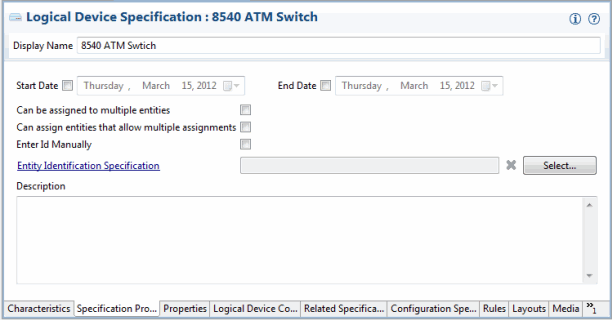
Description of ''Figure 3-2 Entering Basic Identifying Information''
Logical Device specification editors include a tab in which you can enter a vendor, model, or part number that pertains to the logical device you are modeling. Figure 3-3 shows the Properties tab for a Logical Device specification. Not all specification types have a Properties tab, and property data elements vary by entity type.
Figure 3-3 Setting Logical Device Properties
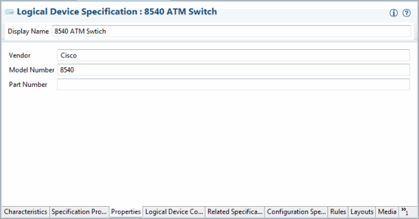
Description of ''Figure 3-3 Setting Logical Device Properties''
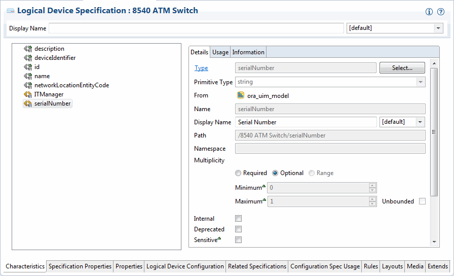
You can add characteristics to an entity specification to store data not supplied by default by the specification type. You can either select from already existing characteristics or them in the process of adding them. Figure 3-4 shows two characteristics added to the Characteristics tab of a Logical Device specification. Information about the selected characteristic is displayed in the editor on the right of the tab.
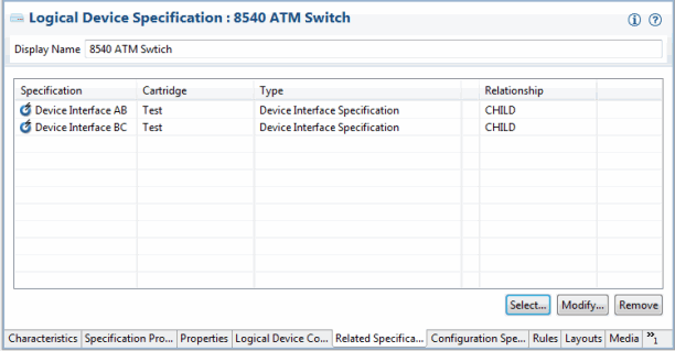
Figure 3-5 illustrates relationships between the Logical Device specification and two Device Interface specifications.
In UIM, these relationships mean that when a logical device is created based on this specification, device interfaces are created automatically based on the minimum values defined in the specification. Users can add OC-3 and OC-12 device interfaces up to the maximum values established in the specification.
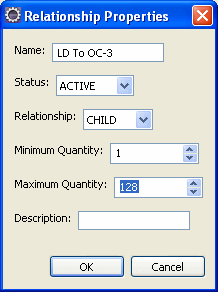
Figure 3-6 shows the relationship properties of the OC-3 device interface. The minimum value means that one OC-3 will be created automatically when a logical device entity is created based on this specification. The maximum values means that users can create an additional 127 interfaces for a total of 128.
Deploying Cartridges into UIM
After you have created a UIM project that includes specifications, rulesets, and other artifacts, you deploy it into UIM. You can deploy cartridges and cartridge packs into UIM using the following methods:
-
From Design Studio. You can deploy cartridges and cartridge packs interactively from Design Studio to test environments. Design Studio enables you to manage cartridges in the test environment consistently, manage common test environment connection parameters across the design team, and compare cartridge version and build numbers in the development environment with those of the cartridges deployed in the test environment. See the Design Studio Help for more information.
-
By using the Design Studio Cartridge Management Tool (CMT). The CMT enables you to automate cartridge deployment. You can use the CMT to deploy cartridges into both test and production UIM environments. You can also use it to deploy cartridges into cluster environments. See the Design Studio Developer's Guide for more information about the CMT.
-
By using the UIM Cartridge Deployer Tool (CDT). The UIM CDT is a GUI-based tool that enables you to deploy to UIM run-time environments. The Oracle Universal Installer installs the CDT as part of the UIM installation process. You can use the CDT to deploy cartridges into both test and production UIM environments. You can also use it to deploy cartridges into cluster environments. See the UIM Cartridge Guide for more information.
