16 Service Connectivity
This chapter explains how you use the service connectivity features in Oracle Communications Unified Inventory Management (UIM).
About Service Connectivity
Service connectivity expresses the requirements of a service in terms of transmission bit rates and the locations to be connected. This type of connectivity is sometimes called a service trail.
Because a service connectivity represents required bandwidth rather than available bandwidth, it cannot have riders. A service connectivity consumes other types of connectivity and resources, but cannot be consumed itself. You can enable service connectivities with channelized connectivity, packet connectivity, or both. The bit rate of a service connectivity cannot exceed that of its enabling connectivity. See UIM Help for more information about enabling connectivities.
Service connectivities are not defined by a technology, so when you create a Service Connectivity specification in Design Studio, the technology is automatically set to Undefined.
Service Connectivity specifications include an attribute (Service Connectivity Controlled) that determines how you create and use service connectivities based on the specification:
-
If Service Connectivity Controlled is not enabled, you create and configure the service connectivity normally. Although it is created outside the context of service configurations, you can include the service connectivity in service configurations. See "Service Connectivity Examples" for an example. See UIM Help for information about creating connectivities, including service connectivities.
-
If Service Connectivity Controlled is enabled, you can create the service connectivity only as part of a service configuration. This type of service connectivity is used in packet-based service arrangements, such as Carrier Ethernet. See "Service Configuration-Controlled Service Connectivities" for more information.
Service Connectivity Examples
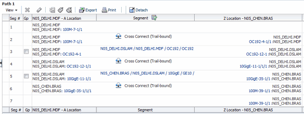
You can use service connectivities to represent services such as VoIP that are enabled by other connectivity. For example, Figure 16-1 illustrates a VoIP service that is enabled by an OC192 connectivity in one segment and a 10 Gbps Ethernet connectivity in another segment.
You can also use service connectivities to represent circuits that are designed internally by a provider and are not initially part of a service. They can be included subsequently in customer service designs.These connectivities are sometimes called Official Use or Company Use circuits.
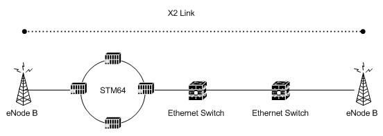
For example, a service connectivity could be used to represent an X2 link connecting cell towers in an LTE backhaul scenario. Figure 16-2 illustrates an X2 link enabled by other connectivities of various different technologies.
Figure 16-2 Service Connectivity for LTE Backhaul

Description of "Figure 16-2 Service Connectivity for LTE Backhaul"
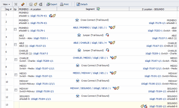
Figure 16-3 illustrates the Connectivity Design tab of this service connectivity. The service connectivity is enable by five Ethernet connectivities, one of which is enabled by the STM64 ring.
Service Configuration-Controlled Service Connectivities
Unlike other connectivity entities, you do not create service configuration-controlled connectivities directly. Instead, you create them in the process of configuring the services to which they are assigned. For example, when you design an Ethernet Access service as part of a Carrier Ethernet E-LAN service, you create a service connectivity. You assign the service connectivity as a configuration item in the Ethernet Access service configuration.
The life cycle of a service connectivity is bound to that of the Service configuration to which it is assigned. When the service connectivity is first created, it can be viewed only from within the Service configuration. It is in Pending Install status and cannot be searched for in UIM.
When the Service configuration is completed, the service connectivity is transitioned to the Current context. It is then visible in the search results.
Similarly when you disconnect a service, the parent service configuration transitions to Pending Disconnect status. This transition propagates to the service connectivity and it is also transitioned to Pending Disconnect. Completing the disconnect of the service completes the disconnect of the service connectivity.
You use service configuration-controlled service connectivities in two contexts:
-
Connecting service locations to the provider network in multipoint services. For example, in a Carrier Ethernet E-LAN service, there are separate Ethernet Access services for each service location. A service connectivity is assigned to the Ethernet Access service configuration.
-
Representing end-to-end service connectivity in point-to-point services. For example, in a Carrier Ethernet E-Line service, a service connectivity is assigned to the service configuration.
Service connectivity designs are created automatically based on the configuration of their parent service. The Connectivity Design tab for service connectivities is read-only.
This type of service connectivity always has at least one end point at a service location. The other end point can be at another service location or at a network location. When assigned to Ethernet Access services, one end point is at a service location and the other is at a network location. When assigned to a point-to-point service such as an E-Line service, both end points are at service locations.
Service Connectivity in Multipoint Services
In a multipoint Carrier Ethernet network, service connectivities are network segments that connect service locations to a service provider network. For each service location, there is an Ethernet Access Service with a corresponding service connectivity. The service connectivity is enabled by the UNI connectivity that connects the CE device at the service location to the PE device at the provider network.
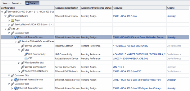
For example, Figure 16-4 illustrates the configuration of an E-LAN service. The service has three customer sites in Boston, Chicago, and New York. The Boston location's service connectivity is VPN / 4 /1, which is enabled by the 4 FANEUILLE MARKET BOSTON US/BOSMA3PRA UNI connectivity. Figure 16-5 illustrates the Connectivity Design tab of the service of VPN / 4 /1.
Figure 16-4 E-LAN Service with Ethernet Access Service and Service Connectivity

Description of "Figure 16-4 E-LAN Service with Ethernet Access Service and Service Connectivity"
Figure 16-5 Service Connectivity Design Tab

Description of "Figure 16-5 Service Connectivity Design Tab"
Service Connectivities in Point-to-Point Services
In a point-to-point service, such as an Ethernet E-Line service, the service connectivity spans the whole service from the A service location to the Z service location. Figure 16-6 and Figure 16-7 illustrate a service connectivity in the context of an E-Line service.
Figure 16-6 E-Line Service with Service Connectivity

Description of "Figure 16-6 E-Line Service with Service Connectivity"
Figure 16-7 E-Line Service with Service Connectivity - Schematic View

Description of "Figure 16-7 E-Line Service with Service Connectivity - Schematic View"
The service connectivity is enabled by UNI connectivities on the service location ends and network transport inside the service provider networks. Figure 16-8 illustrates the design of the service connectivity shown in the previous figures.
A gap enables the service connectivity within the provider network because the service connectivity reflects only the UNI connectivities up to their PVN trunk interfaces. The gap is automatically labeled Gap – Network Transport.
Figure 16-8 E-Line Service Connectivity Design

Description of "Figure 16-8 E-Line Service Connectivity Design"

