Identify Front and Rear Panel Items
Use one of the following illustrations to familiarize yourself with the Roving Edge connectors.
- Roving Edge Device 2 – Rear Panel
- Roving Edge Device 2 – Front Panel
- Roving Edge Ultra – Front Panel
- Roving Edge Device 1 – Rear Panel
To meet MIL-STD-461 Rev G RE102 requirements, all Ethernet network cables attached to the Roving Edge Device must be CAT8 rated. Otherwise, the minimum requirement for Ethernet cables is CAT6.
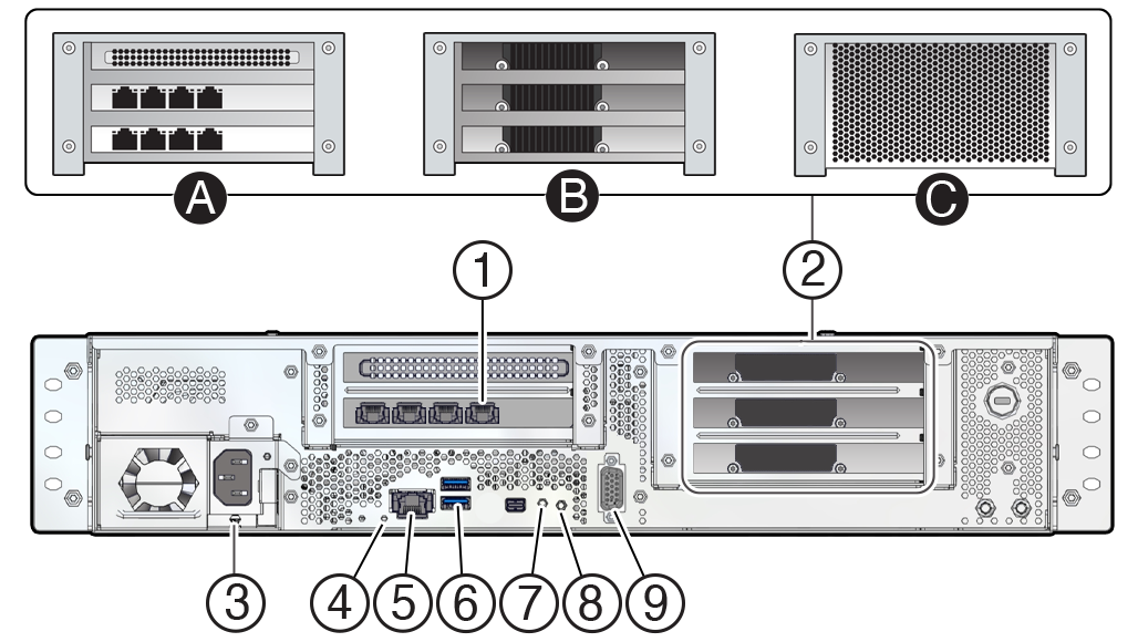
Roving Edge Device 2 – Rear Panel
| No. | Description |
|---|---|
| 1 |
PCIe 0: 1 Quad port 10GBASE-T Ethernet card with RJ-45 port assignments from left to right: 3, 2, 1, 0 For all shapes, use the following ports:
|
| 2A | Compute shape includes 2 additional Quad port 10GBASE-T Ethernet cards. 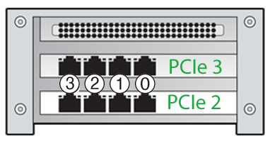 All the ports on PCIe 2 and PCIe 3 can optionally be used for Ethernet bonding with PCIe 0 port 0. You can also optionally use PCIe 0 ports 1 and 2 (see Item 1 in this table). See Managing Ethernet Bonding. |
| 2B |
GPU shape includes 3 NVIDIA AD104GL [L4] GPUs. |
| 2C |
Storage shape includes 4 additional 15.38 SSDs. |
| 3 | Power receptacle |
| 4 |
System status LED
|
| 5 | Reserved RJ-45 port, for Oracle use only. |
| 6 |
Two USB 3.0 ports. Top port is reserved for factory troubleshooting use. Bottom port can be connected to USB-enabled instances. For requirements, see Connecting USB Devices to Instances. |
| 7 | Reset button |
| 8 | Power switch and LED
|
| 9 | DB-9 serial console port. Your initial communication with the device is made through the serial console that's connected to a controlling host computer, such a laptop. See Cable the Roving Edge Device. |
What's next?
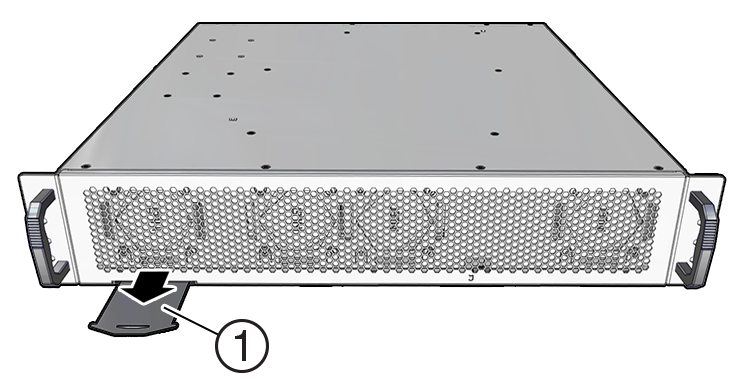
Roving Edge Device 2 – Front Panel
| No. | Description |
|---|---|
| 1 | Pullout card. The card shows where to get the documentation, and lists the serial and model numbers. View both sides of the card. |
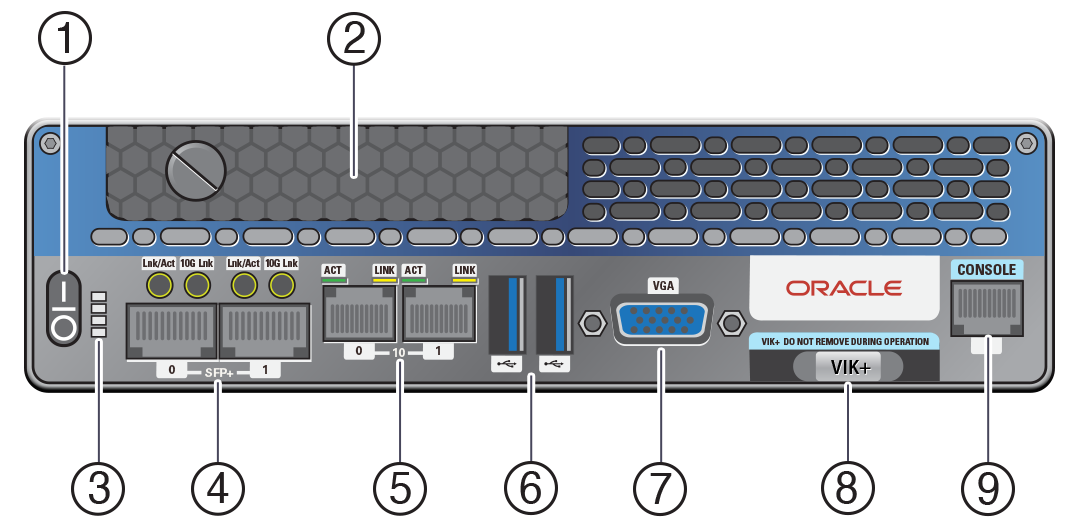
Roving Edge Ultra – Front Panel
| No. | Description |
|---|---|
| 1 | Power switch |
| 2 | One removable SSD |
| 3 | Status LEDs |
| 4 | Two 10 Gb SFP+ Ethernet ports |
| 5 | Two 1 Gb copper Ethernet RJ-45 ports |
| 6 |
Two USB 3.0 ports. Both ports can be connected to USB-enabled instances. For requirements, see Connecting USB Devices to Instances. |
| 7 | Disabled VGA port |
| 8 | NVMe-based VIK+ storage with 512GB capacity |
| 9 | Serial console RJ-45 port |
What's next?
Roving Edge Device 1 – Rear Panel
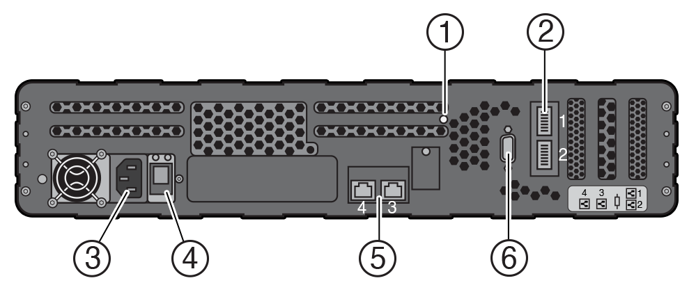
| No. | Description |
|---|---|
| 1 | Power override switch |
| 2 |
Two 100GbE QSFP28 Ethernet ports |
| 3 | Power receptacle |
| 4 | Power switch |
| 5 |
Two 10GB RJ45 Ethernet ports. Use port labeled 4 for connectivity to your network. Port 3 can optionally be used for Ethernet bonding with port 4. See Managing Ethernet Bonding. |
| 6 | DB-9 serial console port |
What's next?