Ingest and Transform Data Using a Data Flow

A data flow is a logical diagram representing the flow of data from source data assets, such as a database or flat file, to target data assets, such as a data lake or data warehouse.

The flow of data from source to target can undergo a series of transformations to aggregate, cleanse, and shape the data. Data engineers and ETL developers can then analyze or gather insights and use that data to make impactful business decisions.

In this tutorial, you:

  1. Create a project where you can save your data flow.
  2. Add source operators and select the data entities to use in the data flow.
  3. Use shaping operators and apply transformations.
  4. Identify the target data asset for loading the data.

Before You Begin

To ingest and transform data using a data flow, you must have the following:

1. Creating a Project and a Data Flow

In Oracle Cloud Infrastructure Data Integration, data flows and tasks can only be created in a project or folder.

To create a project and a data flow:

  1. On your workspace Home page, click Projects.

    You can also click Open tab (plus icon) in the tab bar, and select Projects.

  2. On the Projects page, click Create project.
  3. On the Create project page, enter DI_Lab for Name, and then click Create.

    After you create a project, you can create a data flow to ingest data from two source files, containing customers (CUSTOMERS.json) and orders (REVENUE.csv) information.

  4. On the DI_Lab project details page, click Data flows in the submenu on the left.
    If you are on the Projects page, click DI_Lab to open the project details page.
  5. Click Create data flow.

    The data flow designer opens in a new tab.

  6. In the Properties panel, for Name, enter Load Customers and Revenue Data.

    The Identifier value is auto-generated based on the value you enter for the data flow name. You can change the auto-generated value, but after you save the data flow, you cannot update the identifier.

  7. Click Create.

    The designer remains open for you to continue editing.

2. Adding Source Operators

You add source operators to identify the data entities to use for the data flow. A data entity represents a database table in this tutorial.

Learn more about operators.

  1. From the Operators panel, drag and drop a Source operator onto the canvas.
  2. On the canvas, select SOURCE_1, if it is not already selected.

    The Properties panel displays the details for the operator in focus.

  3. In the Details tab of the Properties panel, click Select next to each of the following options to make your selections:
    • For Data asset, select Data_Lake.
    • For Connection, select Default connection.
    • For Schema, select your compartment and then your bucket. For the purposes of this tutorial, Object Storage serves as the source data asset, this is why you select your bucket here.
    • For Data entity, click Browse by name and then select CUSTOMERS.json. For File type, select JSON.
  4. When you complete your selections for SOURCE_1, the operator name becomes CUSTOMERS_JSON, reflecting your data entity selection. In the Identifier field, rename the source operator to CUSTOMERS.
  5. Repeat steps 1 through 3 to add a second Source operator with the following values:
    • For Data asset, select Data_Lake.
    • For Connection, select Default Connection.
    • For Schema, select your compartment and then your bucket. For the purposes of this tutorial, Object Storage serves as the source data asset, this is why you select your bucket here.
    • For Data entity, select REVENUE.csv, and then select CSV for the file type. Accept the default values for the remaining items.
  6. When you complete your selections for the second source operator, the operator name becomes REVENUE_CSV, reflecting your data entity selection. In the Identifier field, rename the source operator to REVENUE.
  7. (Optional) Click Assign parameter to keep the source details from being bound to the compiled code, when you publish the data flow.

    Learn more about Parameters.

  8. (Optional) In the Attributes tab, you can view the data entity's attributes and apply exclude or rename rules to the attributes from their respective Actions icon (three dots).
    You can also use the filter icon on the Name or Type column to apply one or more filters on the attributes to be excluded.
  9. (Optional) In the Data tab, you can view a sampling of data from the source data entity and apply transformations to the data or select attributes to view a data profile.

    Learn more about Data Xplorer.

  10. (Optional) In the Validation tab, you can check for warnings or errors with the configuration of the source operators.
  11. To save the data flow and continue editing, click Save.

3. Filtering and Transforming Data

Filtering Data

The Filter operator produces a subset of data from an upstream operator based on a condition.

  1. From the Operators panel, drag and drop a Filter operator onto the canvas.
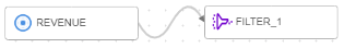
  2. Connect REVENUE to FILTER_1:
    • Place your cursor on REVENUE.
    • Drag the connector circle at the side of REVENUE.

      Connector for operators

    • Drop the connector circle on FILTER_1.

      Drag-and-drop action between connectors

  3. Select FILTER_1.
  4. In the Properties panel, click Create next to Filter condition.
  5. In the Create filter condition panel, enter STA in the Search by name field.
  6. Double-click or drag and drop ORDER_STATUS to add it to the filter condition editor.
  7. In the condition editor, enter ='1-Booked', so your condition looks like the following:

    FILTER_1.REVENUE_CSV.ORDER_STATUS='1-Booked'

    Note

    To avoid issues with the quotes, do not copy and paste.
  8. Click Create.
  9. From the Operators panel, drag and drop a Filter operator onto the canvas, placing it after CUSTOMERS.
  10. Connect CUSTOMERS to FILTER_2:
    • Place your cursor on CUSTOMERS.
    • Drag the connector circle at the right-side of CUSTOMERS.
    • Drop the connector circle on FILTER_2.
  11. In the Properties panel for FILTER_2, click Create next to Filter condition.
  12. In the Create filter condition panel, enter COU in the Search by name field.
  13. Double-click COUNTRY_CODE to add it to the condition editor.
  14. Enter ='US', so that your condition looks like the following:

    FILTER_2.CUSTOMERS_JSON.COUNTRY_CODE='US'

  15. Click Create.
  16. To save the data flow and continue editing, click Save.
Transforming Data

Using Data Xplorer, you can explore a data sample, review profiling metadata, and apply transformations in the Data tab of the Properties panel. Expression operators are added to the canvas for each transformation applied.

  1. In the Properties panel for FILTER_2, select the Data tab.
    All data rows and attributes are displayed. You can use the vertical scrollbar to scroll the rows, and the horizontal scrollbar to scroll the attributes.
  2. In the Search by pattern field, enter STATE*.
    The number of attributes in the table are filtered. Only those attributes that match the pattern are displayed.
  3. Click the transformations icon (three dots) for FILTER_2.CUSTOMERS_JSON.STATE_PROVINCE, and then select Change case.
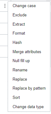
    Transformation menu icon

  4. In the Change case dialog, from the Type menu, select Upper.
  5. Do not select the Keep source attributes check nox.
  6. Leave the Name as-is.
  7. Click Apply.

    An expression operator is added to the data flow. In the Properties panel, the Details tab is now in focus, showing the details of the expression operator.

    In the Expressions table, you can see the generated expression, UPPER(EXPRESSION_1.CUSTOMERS_JSON.STATE_PROVINCE).

  8. In the Properties panel for the expression operator, change the name in the Identifier field to CHANGE_CASE.
  9. Click the Data tab, and then use the horizontal scrollbar to scroll to the end.

    CHANGE_CASE.STATE_PROVINCE is added to the end of the dataset. You can preview the transformed data for CHANGE_CASE.STATE_PROVINCE in the Data tab.

  10. From the Operators panel, drag and drop the Expression operator onto the canvas, placing it after CHANGE_CASE.
  11. Connect CHANGE_CASE to the new EXPRESSION_1 operator.
  12. In the Properties panel for EXPRESSION_1, select Add expression in the Expressions table.
  13. In the Add expression panel:
    1. In the Identifier field, rename the expression to FULLNAME.
    2. Keep Data type as VARCHAR.
    3. Set Length to 200.
    4. Under Expression builder, switch from the Incoming list to the Functions list.
    5. In the search by name field, enter CON. Then locate CONCAT under String.
    6. Enter CONCAT(CONCAT(EXPRESSION_1.CUSTOMERS_JSON.FIRST_NAME, ' '),EXPRESSION_1.CUSTOMERS_JSON.LAST_NAME)

      You can also highlight a function's placeholders and then double-click or drag and drop attributes from the Incoming list to create an expression.

    7. Click Add.

    The CONCAT expression is now listed in the Expressions table for the EXPRESSION_1 operator. You can add as many expressions as you want.

  14. To save the data flow and continue editing, click Save.

4. Joining Data

After you apply filters and transformations, you can join the source data entities using a unique customer identifier, and then load the data into a target data entity.

  1. To join the data from EXPRESSION_1 with the data from FILTER_1, drag and drop a Join operator from the Operators panel onto the canvas, placing it after to EXPRESSION_1 and FILTER_1.
  2. Connect EXPRESSION_1 to JOIN_1. Then connect FILTER_1 to JOIN_1.
  3. With JOIN_1 selected, in the Details tab of the Properties panel, click Create next to Join condition.
  4. In the Create join condition panel, enter CUST in the search by name field.
    You want to join the entities using CUST_ID and CUST_KEY.
  5. In the editor, enter JOIN_1_1.CUSTOMERS_JSON.CUST_ID=JOIN_1_2.REVENUE_CSV.CUST_KEY.
  6. Click Create.
  7. To save the data flow and continue editing, click Save.

5. Adding a Target Operator

  1. From the Operators panel, drag and drop a Target operator onto the canvas.
  2. Connect JOIN_1 to TARGET_1.
  3. Select TARGET_1 on the canvas, if it is not already selected.
  4. In the Details tab of the Properties panel, do not select the Create new data entity check box.
  5. Next, click Select for each of the following options to make your selections for a data entity:
    • For Data asset, select Data_Warehouse.
    • For Connection, select Default Connection.
    • For Schema, select BETA.
    • For Data entity, select CUSTOMERS_TARGET.
  6. For Staging location, select the Data Lake data asset, its default connection, and your compartment. Then for Schema, select the Object Storage bucket that you used to import the sample data.
  7. Leave the value for Integration strategy as Insert.
  8. To review the Attributes mapping, click the Map tab.

    By default, all attributes are mapped by name.

    For example, CUST_ID from JOIN_1 maps to CUST_ID in the target data entity.

  9. To manually map attributes that are not yet mapped, select the All menu in the Target attributes table, and then select Attributes not mapped.

    You can do the same in the Source attributes table (for the incoming fields).

  10. Now drag and drop FULLNAME from Source attributes to FULL_NAME in Target attributes.
  11. In the Target attributes table, select Attributes not mapped, and then select All.

    All attributes are now mapped.

  12. (Optional) Click Actions to review the various auto-mapping options available.

    Learn more about mapping options.

  13. (Optional) Click View rules to view the applied Rules.
  14. To save the data flow and exit the designer, click Save and close.