Preparing the Data Center Network Environment
The network architecture of Oracle Private Cloud Appliance relies on physical high speed Ethernet connectivity. Prepare the data center network configuration so it meets the requirements for incorporating the appliance.
The networking infrastructure in Private Cloud Appliance is integral to the system and must not be altered. The networking does not integrate into any data center management or provisioning frameworks such as Cisco ACI, Network Director, or the like.
However, Private Cloud Appliance can communicate with the Cisco ACI fabric in your data center using the L3Out functionality (static routes or eBGP) provided by Cisco ACI. For more information about this Cisco feature, see the Cisco ACI Fabric L3Out Guide.
No changes to the networking switches in Private Cloud Appliance are supported, unless when instructed by Oracle Support or through a knowledge article on the My Oracle Support website.
For important conceptual information about appliance networking, see Private Cloud Appliance Network Infrastructure. It describes the different networks and their roles, the uplinks that connect to the data center network, and the network resources reserved for appliance operation.
Appliance Uplink Requirements
When preparing for the installation of Private Cloud Appliance, select an uplink configuration and set up the data center network to accept this configuration.
On each spine switch, ports 1 to 4 can be used for uplinks to the data center network. For speeds of 10Gbps or 25Gbps, the spine switch port must be split using a 4-way splitter or breakout cable. For higher speeds of 40Gbps or 100Gbps each switch port uses a single direct cable connection.
The uplinks are configured during system initialization, based on information you provide as part of the Initial System Installation Checklist. Unused spine switch uplink ports, including unused breakout ports, are disabled for security reasons.
It is critical that both spine switches have the same connections to the next-level data center switches. This configuration provides redundancy and load distribution at the level of the spine switches, the ports, and the data center switches. This outbound cabling depends on the network topology you deploy. The cabling pattern plays a key role in the continuation of service during failover scenarios.
For detailed information about choosing the appropriate configuration, and about the available topologies (Mesh, Square, Triangle) see Uplinks. Configuration guidance and reference examples are also provided.
-
Before installation, you must run network cables from your existing network infrastructure to the Private Cloud Appliance installation site. For instructions see Connecting Private Cloud Appliance to the Data Center Network.
-
Plan to connect at least 1 high-speed Ethernet port on each spine switch to your data center public Ethernet network.
-
Configuring the optional Administration network requires 2 additional cable connections (one each from port 5 on the two spine switches) to a pair of next-level data center switches.
-
Uplink connectivity is based on layer 3 of the OSI model.
-
When upgrading from appliance software version 3.0.2-b892153 or earlier, and running vPC/HSRP, if you want to change the network configuration to support new features, contact Oracle for assistance.
Data Center DNS Configuration for Private Cloud Appliance
To integrate the data of the dedicated Private Cloud Appliance DNS zone into the data center DNS configuration, two options are supported: zone delegation or manual configuration.
The preferred approach is to configure zone delegation. However, if you select manual configuration, it is good practice to register network host names and IP addresses for the management network, client network, and additional public networks in the data center Domain Name System (DNS) prior to initial configuration. In particular, all public addresses, VIP addresses and infrastructure services endpoints should be registered in DNS prior to installation.
All addresses registered in DNS must be configured for forward resolution; reverse resolution is not supported in the Private Cloud Appliance services zone.
Zone Delegation (preferred)
For zone delegation to work, it is required that the data center's recursive caches are able to reach TCP/UDP port 53 on the virtual IP address shared by the appliance management nodes. It may be necessary to change your firewall configuration.
Configure the data center DNS server so that it operates as the parent zone of the appliance DNS zone. Thus, all DNS requests for the child zone are delegated to the appliance internal DNS server. In the data center DNS configuration, add a name server record for the child zone and an address record for the authoritative server of that zone.
In the example it is assumed that the data center DNS domain is example.com, that the appliance is named mypca, and that the management node cluster virtual IP address is 192.0.2.102. The appliance internal DNS server host name is ns1.
$ORIGIN example.com.
[...]
mypca       IN    NS    ns1.mypca.example.com.
ns1.mypca IN A 192.0.2.102DNS lookup for services endpoints has changed in controller software version 3.0.2-b1483396. Individual address records per service have been consolidated into CNAME records referencing a common services or adminservices record. With zone delegation of the appliance subdomain, lookups for a defined RTYPE return the CNAME record and the RTYPE. Lookups for undefined RTYPEs that previously returned no answer, now return a CNAME record only.
Manual Configuration
Manually add DNS records for all labels or host names required by the appliance.
In the examples it is assumed that the data center DNS domain is example.com, that the appliance is named mypca, and that the management node cluster virtual IP address is 192.0.2.102 in the data network and 203.0.113.12 in the (optional) administration network.
For object storage you must point the DNS label to the Object Storage Public IP. This is the public IP address you assign specifically for this purpose when setting up the data center public IP ranges during Initial Setup.
|
Appliance Infrastructure Service and DNS Label |
Data Center DNS Record |
Data Center DNS Record with Admin Network Enabled |
|---|---|---|
|
Admin service
|
|
|
|
Networking, Compute, Block Storage, Work Requests services
|
|
|
|
Identity and Access Management service
|
|
|
|
DNS service
|
|
|
|
Object storage
Use the Object Storage Public IP from the Appliance Initial Setup. |
|
|
|
File storage
|
|
|
|
Alert manager
|
|
|
|
API
|
|
|
|
OKE service
|
|
|
|
Resource principal service
|
|
|
|
Grafana
|
|
|
|
Prometheus
|
|
|
|
Prometheus-gw
|
|
|
|
Service Web UI
|
|
|
|
Compute Web UI
|
|
|
Data Center Network Configuration Guidelines
Follow these important guidelines for a smooth integration of Private Cloud Appliance into the data center network.
Data Center Switch Notes
-
All uplinks, default and customer, are configured to use link aggregation (LACP). All switch ports included in an uplink configuration must belong to the same link aggregation group (LAG). The switch ports on the data center side of the uplinks must be configured accordingly.
-
The spine switches operate with the Virtual Port Channel (vPC) feature enabled in static routing configurations.
-
Private Cloud Appliance supports layer 3 based uplink connectivity to the customer data center. Static routing and BGP4-based dynamic routing are supported in layer 3.
-
Autonegotiation isn't available for uplink ports. Transfer speed must be specified on the customer switches' end.
For more information, see Uplinks and Uplink Protocols.
Administration Network Guidelines
If you choose to segregate administrative appliance access from the data traffic, ensure that the data center network is configured accordingly, so that all traffic can be routed to the appropriate destinations in both the administration and the data network.
- Access to Service Endpoints
-
When the administration network is enabled, some appliance infrastructure services are accessed through the Admin Management VIP, instead of the regular Management Node VIP. These service endpoints are:
-
'admin'
-
'adminconsole'
-
'prometheus-gw'
-
'prometheus'
-
'grafana'
-
'api'
-
'alertmanager'
-
'rps'
The following service endpoints are always accessed through the Management Node VIP in the data network:
-
'console'
-
'iaas'
-
'identity'
-
'filestorage'
-
'objectstorage'
-
'dns'
-
'containerengine'
Ensure that the data center firewall is configured to allow this traffic. If you manage the DNS records required by the appliance in the data center DNS configuration, ensure that they point to the correct network and address, as shown in Data Center DNS Configuration for Private Cloud Appliance (Manual Configuration).
-
- OKE Cluster Management
-
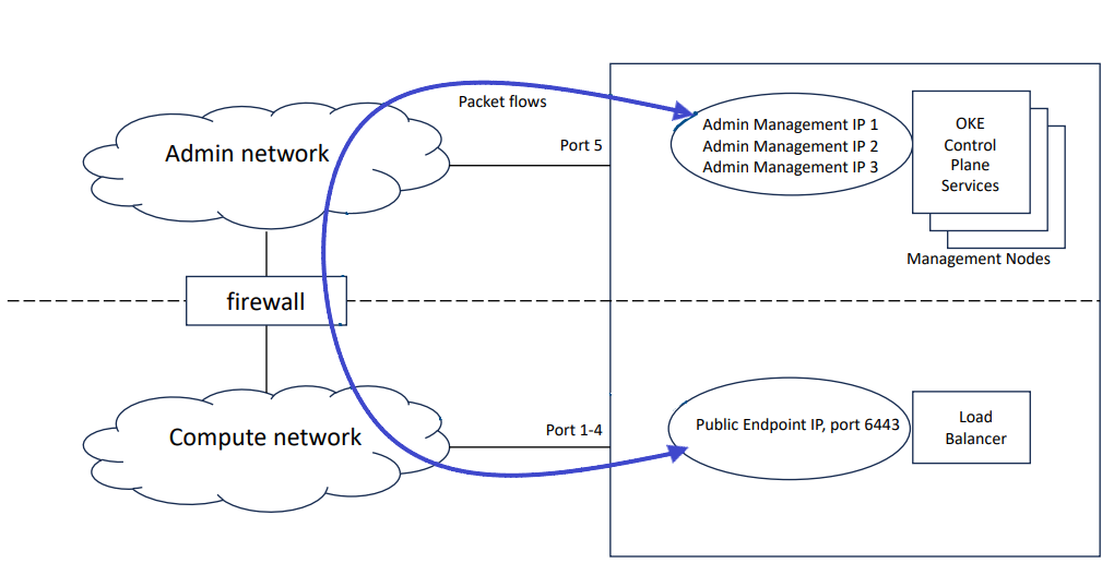
When Kubernetes Engine is used on a system configured with a separate administration network, the data center firewall must be configured to allow traffic between the OKE control plane and the OKE clusters deployed by Compute Enclave users.
The OKE control plane runs on the management nodes in the administration network, while the OKE clusters are deployed in the data network. The management interface of an OKE cluster is port 6443 on its load balancer public IP address. This address is assigned from the data center IP range you reserved and configured as public IPs during initial appliance setup.
Because of the network segregation, traffic from the OKE control plane must exit the appliance through the administration network, and reenter through the data network to reach the OKE cluster. The data center network infrastructure must allow traffic in both directions. Without the necessary firewall and routing rules, users cannot deploy OKE clusters.
Default System IP Addresses
The management IP address represents a component's connection to the internal administration network.
For hardware management, Private Cloud Appliance uses a network internal to the system. It is not recommended to connect the management ports or the internal administration network switches to the data center network infrastructure.
The table in this section lists the default management IP addresses assigned to servers and other hardware components in a Private Cloud Appliance base configuration.
|
Rack Unit |
Rack Component |
Management IP Address Assigned During Manufacturing |
|---|---|---|
|
32 |
Spine Switch |
|
|
31 |
Spine Switch |
|
|
26 |
Management Switch |
|
|
25 |
Leaf/Data Switch |
|
|
24 |
Leaf/Data Switch |
|
|
Management Node VIP |
ILOM: |
|
|
7 |
Management Node |
ILOM: |
|
6 |
Management Node |
ILOM: |
|
5 |
Management Node |
ILOM: |
|
Storage VIPs |
Performance pool Capacity pool |
|
|
3-4 |
Oracle ZFS Storage Appliance Controller Server (2 rack units) |
ILOM: |
|
1-2 |
Oracle ZFS Storage Appliance Controller Server (2 rack units) |
ILOM: |
Compute nodes are assigned an IP address in the internal administration network during the provisioning process. The system IP address is DHCP-based; the ILOM is assigned the system IP, where the third octet is changed from 2 to 0. For example: if a compute node receives IP 100.96.2.64 , then its ILOM has IP 100.96.0.64 . When assigned to a host, these IP addresses are stored and persisted in the DHCP database.