Before You Begin
This section covers Amazon Web Services infrastructure with the EPM 11.2 installation prerequisites, including system requirements, WebLogic configuration, and software dependencies.
For a detailed description of all the architectural options and the design considerations, see Design the infrastructure to deploy Oracle Enterprise Performance Management in the cloud.
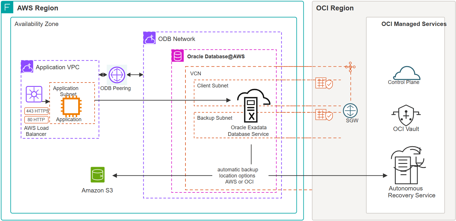
Oracle Database@AWS extends Oracle Database capabilities into AWS as a native service. The following architecture diagram shows the primary topology for Oracle Database@AWS with application resources within a VPC of an AWS region in the same availability zone.
Oracle Database@AWS is a service that provides access to Oracle Exadata infrastructure, managed by Oracle Cloud Infrastructure (OCI), within AWS data centers. It enables you to migrate Oracle Exadata workloads, establish low-latency connectivity with applications running on AWS, and integrate with AWS services.
The following diagram provides a high-level overview of an OCI region connected to an AWS data center that hosts Oracle Exadata infrastructure. Within an AWS Availability Zone (AZ), you can establish up to 45 peering connections between your Amazon VPCs and the private network associated with the data center. These peering connections enable application servers running in the VPCs to access Oracle databases hosted on the Oracle Exadata infrastructure.
To learn more about deploying multicloud and running Oracle AI Database@AWS.
Review these Useful Resource links:
- Deploy Oracle AI Database@AWS
-
Oracle Cloud Infrastructure for Amazon Web Services professionals
- Oracle AI Database@AWS documentation (Oracle)
Table 6-1 Overview of Architecture and Amazon Web Services components
| Component | Purpose |
|---|---|
| Oracle EPM OHS | The Oracle EPM OHS tier consists of web servers that run independently on two Compute Engine VMs. |
| Oracle EPM Application | The Oracle EPM mid tier consists of Windows Server running independently on Compute Engine VMs. |
| Virtual Network and Subnet | All of the Amazon Web Services resources in the architecture use a single VNet. The web servers, mid-tier components, and databases are in separate subnets. Subnet where Oracle Database@AWS are deployed is delegated to Oracle |
| Oracle Database@AWS |
Oracle AI Database@AWS Services provides Oracle Exadata Database deployed and operated in Amazon Web Services with native Amazon Web Services integration. It combines Oracle Exadata Database performance and Oracle AI Database capabilities with Amazon Web Services networking, security, and consumption models. The offering includes Oracle Exadata Database, Oracle Exadata Database Service on Exascale Infrastructure and Oracle Base Database Service for hosting database layer for Oracle Hyperion. The Oracle EPM applications read data from and write to Oracle databases in Oracle Exadata Database Service. You provision Oracle Exadata Database Service by using Oracle AI Database@AWS Services. You use Amazon Web Services interfaces like the Amazon Web Services Portal, the Amazon Web Services CLI, and APIs to create Exadata Infrastructure instances. To optimize the latency between the application and the database, deploy the application in the same zone where you create the Exadata Infrastructure instances. |
| Exadata Infrastructure instance | The Exadata Infrastructure instance contains two or more physical database servers and three or more storage servers. These servers, which aren't shown in the diagram, are interconnected using a low-latency network fabric. When you create the Exadata Infrastructure instance, you specify the number of database servers and storage servers that must be provisioned. |
| Exadata VM Clusters |
Within the Exadata Infrastructure instance, you create one or more Exadata VM Clusters. For example, you can choose to create and use a separate Exadata VM Cluster to host the databases that are required for each of your business units. Each Exadata VM Cluster contains one or more Oracle Linux VMs that host Oracle Database instances. When you create an Exadata VM Cluster, you specify the following:
The VMs within Exadata VM Clusters are not Compute Engine VMs. |
| Oracle Database instances | You create and manage Oracle Database instances through the Oracle Cloud Infrastructure (OCI) console and other OCI interfaces. Oracle Database software runs on the VMs within the Exadata VM Cluster. When you create the Exadata VM Cluster, you specify the Oracle Grid Infrastructure version and choose the license type. You can either bring your own licenses (BYOL) or opt for the license-included model. |
Table 6-2 Configuration and Architecture Details for Oracle EPM 11.2.25 Deployment on Amazon Web Services Cloud
| Amazon Web Services Cloud Setup Process | Details |
|---|---|
| EPM Architecture |
Assign Server Roles to the EPM Applications. Assign application components to the Virtual Machine (VM)s, for example:
|
| Set Up a Shared Storage Location |
Windows Network Share: How to create Network Share on Virtual Machine (VM) 1: Example 1:: Example 2:
|
| Virtual Machine (VM) Provisioning |
Determine the number of VMs needed:
|
| Virtual Machine (VM) Requirements Summary |
Virtual Machine (VM) Requirements
|
| Domain Requirements |
NOTE: All EPM Application VMs must join a Windows Domain.
|
| Domain Setup |
|
| Domain Credentials |
|
| Install and Configure |
Oracle EPM Standard Deployment Guide to install EPM components, adjusting for your topology. |
| Deployment Difference |
|
Configure Oracle HTTP Server and AWS Load Balancer for SSL Offloading
Perform the following administrative user task, before managing an Oracle EPM deployment behind an AWS load balancer.
Note:
Java web applications do not connect directly to the server; you should set up the logical web address for deployments that use a load balancer or an SSL off loader.Prerequisites Steps: SSL offloading and logical web address configurations are supported for AWS deployments using load balancers and SSL off loaders.
Note:
The following settings are only required when terminating SSL at the Load Balancer.Table 6-3 Review the following SSL offloading and logical web address configuration settings
| Component | Setting Category | Parameter | Value |
|---|---|---|---|
| Oracle HTTP Server (OHS) | httpd.conf | LoadModule | LoadModule certheaders_module
${PRODUCT_HOME}/modules/mod_certheaders.so |
| httpd.conf | SimulateHttps | ON | |
| httpd.conf | ProxyErrorOverride | Off | |
| mod_wl_ohs.conf | WLProxySSLPassThrough | ON | |
| AWS EC2 Load Balancer | Load Balancer Attributes | Drop invalid header fields | Off |
| Load Balancer Attributes | X-Forwarded-For header | Preserve | |
| Load Balancer Attributes | Client port preservation | Off | |
| Load Balancer Attributes | Preserve host header | Off | |
| AWS EC2 Load Balancer Target Group | Target Selection Configuration | Stickiness | ON |
| Target Selection Configuration | Stickiness Type | Load balancer generated cookie | |
| Target Selection Configuration | Stickiness Duration | 1 day |
Table 6-4 Configuration Summary
| Layer | Configuration Purpose |
|---|---|
| Oracle HTTP Server | Enables SSL header processing and HTTPS simulation when SSL is terminated at the load balancer. |
| WebLogic/OHS Integration | Passes SSL information from OHS to WebLogic using WLProxySSLPassThrough ON. |
| EC2 Application Load Balancer (ALB) | Preserves client forwarding information while performing SSL offloading. |
| AWS Target Group | Maintains user session persistence through load balancer-generated cookies for 24 hours. |