Creating an Enterprise Process Model for Requisition
Creating an Enterprise Process Model for Requisition
A Process Designer or Business Analyst can create the requisition process model in the
Enterprise Process Manager. To create a process model, you must select a template
provided by the system and configure the source of data for metrics, measurements, and
KPIs, and define certain aggregations or calculations (sum, average, and so on) for
those metrics. You can then save your configurations as a process UDO.
To create a new enterprise process:
Access the JD Edwards EnterpriseOne application.
From the user drop-down list, click Manage Content, and select
Processes.
The system displays the Create Process window.
Note: The Create Process window is only displayed when you are creating an
enterprise process for the first time. After creating a process, when you click
Processes again, the system displays the previously created process layout along
with the template used for its creation and the Enterprise Process Manager
options.
If you want to create a new process, in the Enterprise Process
Manager window, click the Name drop-down list and select Create.
From the Import Process Template drop-down list, select JDE TMPL P2P
Requisitions template.
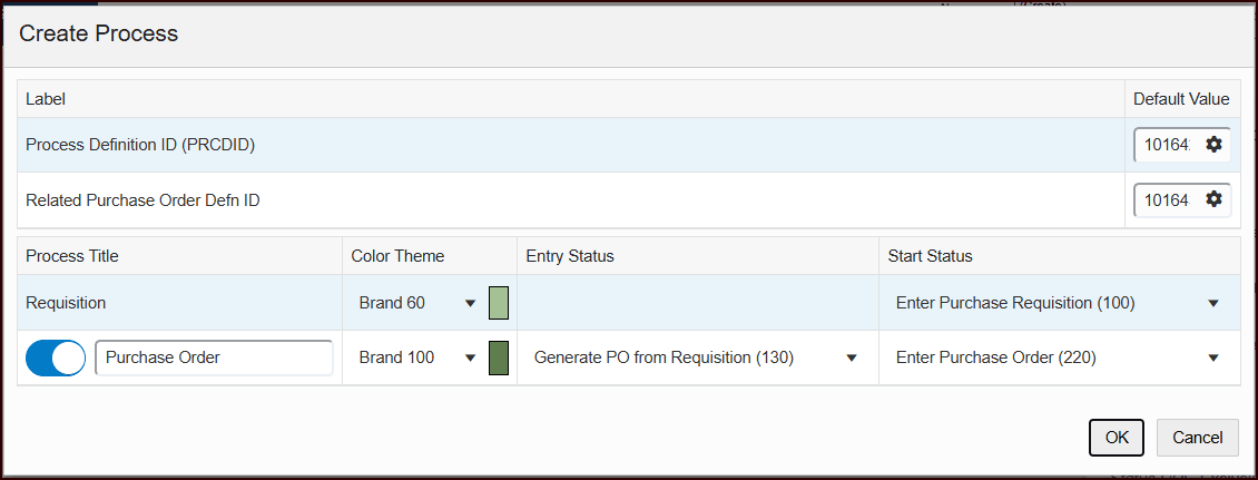
Click OK. The Process Definition ID, and Related Purchase Order Defn
ID default values are displayed in the Create Process window. You can
edit the values or accept the default values.
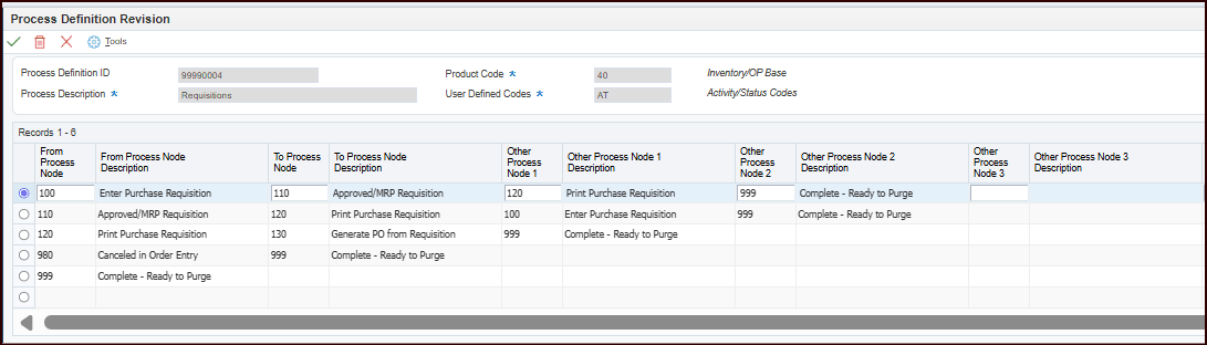
Use the Work with Process Definition application (P00201) to
define process flows using values from the User-Defined Codes (UDC)
tables. The following example shows a reference process definition
configuration for the requisition process. For more information, see
Setting Up Process Definition Records for Procure to Pay Process Model Templates.
Note: You must set up process definition IDs for the enterprise processes. The
Enterprise Process Modeler uses your process definition setup to automatically
generate process flow diagrams. For more information, see Setting Up a Process Definition Record Using P00201 in the JD Edwards
EnterpriseOne Tools Enterprise Process Modeler Guide.
For the Requisition process, select the Color Theme and Start Status
from their respective drop-down lists. The system populates the drop-down list with
available nodes for the requisition template. The selected value in this field
serves as the first (start) node in the automatically generated process model. By
default, the Start Status is set to Enter Purchase Requisition
(100).
From the Requisition process, you can connect to the Purchase Order process by
enabling the toggle button in the Purchase Order row. When enabled, you can
select a color for the drill-down button that links the Requisition process to the
Purchase Order process. This selected color is also applied to all nodes within the
Purchase Order process. In this scenario, the Requisition process serves as the
parent process, while the Purchase Order process functions as the child
process.
Note: By default, the Connected Processes toggle button is enabled for
the Purchase Order process. If you do not want to view the connected processes
from the Requisition process, you must disable the toggle button.
Select the Entry Status from the drop-down list. This field is required to
specify the status from which the requisition process establishes a connection to
the Purchase Order process through a button.
Select the Start Status from the drop-down list. The system displays the
available nodes for the Purchase Order template in this list. The value you select
becomes the first (start) node in the automatically generated process model. By
default, the Start Status is set to Enter Purchase Order (220).
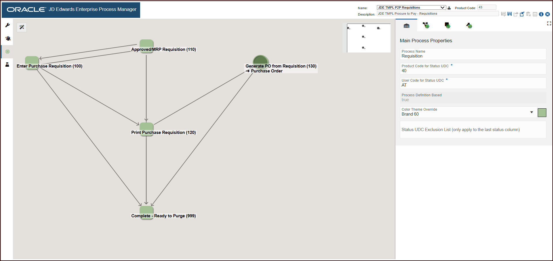
Click OK. The Main Module tab is displayed in the Enterprise Process Manager window,
where you can see the automatically generated enterprise process diagram based on
the values defined in the Create Process window and the Process Definition ID that
you set. The enterprise process diagram displays nodes and the links between the
nodes. The nodes represent the tasks in the process template and the links represent
the connection between the nodes.
Click the save icon. Enter a name for the process model in the Enter New Name
window.
Click OK.
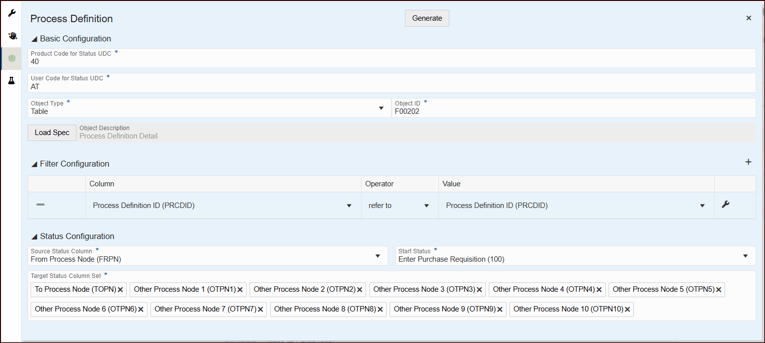
Click the Open Process Definition icon (next to Design Option) to review the
settings in the read-only tab with Basic Configuration, Filter
Configuration, and Status Configuration details.
The Process Definition window opens. You can view the Basic Configuration,
Filter Configuration, and Status Configuration details based on the
values defined in the Create Process window and the process definition that you have
set. These configurations are used to build the nodes and links and to automatically
generate the process model.
The Basic Configuration section displays the UDC - Activity/Status Codes
(40/AT) and the table that the system uses to generate the template - Process
Definition Detail table (F00202).
The Filter Configuration section displays the columns based on which the data
is filtered. The system filters the data based on Order Type and Line Type values
for the Requisition process modeler.
The Status Configuration section displays the Source Status Column,
Start Status, and Target Status Column Set.