Add New Edges During Graph Creation

When creating or editing a graph, you can visually add new edges between two vertex tables through drag and drop action.

You can perform this action inside the Designer tab at the Define Graph step of the graph creation workflow.

The following steps describe the process for visually creating a new edge when using the property graph wizard. The instructions assume that you are at the Define Graph step of the property graph wizard, and more than one vertex tables are selected for building the graph.
  1. Click the Designer tab.

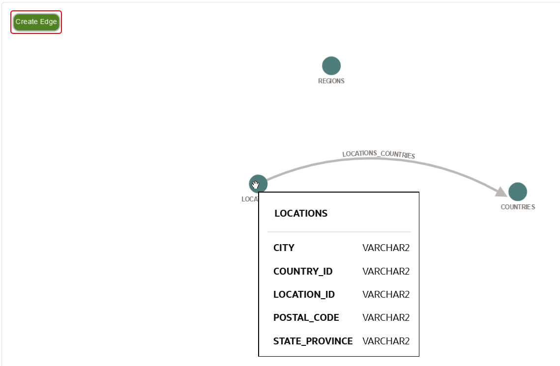
    A preview of the graph to be created is displayed. For example:


    You can drag and move the vertices as required inside the tab. When you hover over a vertex, a tooltip describing the vertex properties is displayed. Alternatively, you can right-click on a vertex to view the vertex properties.

  2. Click Create Edge (shown highlighted in the preceding figure) to activate the mode to add a new edge.
    In this mode, starting a drag action from a vertex will start drawing an arrow (depicting an edge) from the source vertex until it is released on the destination vertex.
  3. Drag an arrow from the desired source vertex and drop it on the target destination vertex to add a new edge.
    Note that if you drag an arrow from a vertex table to itself, then a self edge is created. This indicates that the source and destination tables are the same.

    The Create Edge slider opens as shown:


    Description of create_edge_slider.png follows
    Description of the illustration create_edge_slider.png

  4. Select the Edge Table.
    The list of choices for the edge table is obtained from the input tables selected in the Select Tables step of the property graph wizard.
  5. Select the Edge Source key and Edge Destination key.
  6. Select the source and destination vertex keys using the References source vertex key and References destination vertex key drop-downs respectively.
    Note that these key columns must correspond to a unique (foreign) key of the source and destination vertex tables.
  7. Optionally, modify the Edge Label.
  8. Select the Edge Properties.
    You can choose any combination of the columns of the edge table as edge properties. By default, these edge properties will automatically be assigned the name of the column. If you wish to add all the columns of the edge table, then you can simply click Add all properties.
  9. Click Create Edge.
    The new edge is shown displayed between the two vertex tables. You can click on the edge to review and verify the edge configuration as shown.


    Description of view_edge_details.png follows
    Description of the illustration view_edge_details.png

    Optionally, you can click Delete Edge if you wish to delete the edge.

    All edges added or deleted in the Designer tab will be reflected in the CREATE PROPERTY GRAPH statement in the Source tab.