Create Decision Tables
Decision tables are the notation of choice to model complex logic. Their tabular layout helps you effectively document all the possible conditions and results of a problem.
-
In graph view, click Expand
 next to Decision on the diagram palette. Select Decision Table and drag it onto the canvas. Double-click the element to edit its logic. You can also edit the table's logic from the properties pane; select the table element, then select Open Properties
  , and in the properties pane click Edit
  next to the Name field.
Click Close
 to return to the canvas.
-
In list view, click Add new decision
 in the Decisions bar and select Decision Table from the Create Decision window. An empty decision table appears.
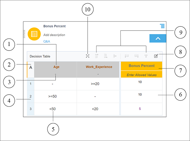
The following figure shows an example decision table with all its elements noted:
-
Input Expression cell – Contains the expression associated with a particular input column or clause.
-
Hit Policy Indicator cell – Displays the hit policy selected for the table.
-
Allowed Values cell – Displays permitted values for cell entries of that column.
-
Rules – Rows within the table.
-
Input Entry cell – Contains an input entry.
-
Output Entry cell – Contains an output entry.
-
Output Label cell – Contains the name of the decision.
-
Add Annotation button – Adds a column for documenting or annotating decision rules. Annotations aren’t considered as part of the decision logic; they serve as explanatory notes for designers.
Note:
The Add Annotation button disappears after you add the first annotation column. However, you can add additional columns for annotations using the column add controls. -
Row and column controls – Add or remove rows and columns.
-
Expand Table – Opens the table in an expanded view.
The following sections explain each decision table element in detail:
