Axle Weight for Rail Equipment
Axle Weight for Rail Equipment
Axle Weight for Rail Equipment is an enhancement that is based on public safety. The Axle Weight is a requirement for safe carriage as rail carriers demand that shippers tender safe loads and have the means to prove that the loads are safe. This is done either by a certified scale or is done by an approved calculation. This is an example of the calculation.
For example, in North America, the standard is now 286,000 pounds Gross Weight per rail car which translates to a maximum of 71,500 pounds per axle for typical cars with 4 axles. Shippers with a Shippers Weight Agreement do not have to weigh each car as they can certify that the packing for the freight has been calculated and is within limits. Railroads will weigh cars in the process of transport and will access fines if overloaded.
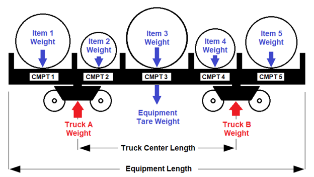
Another requirement is that there is also a “balance” between the two supporting points as noted in the following diagram. A parameter is provided to configure a tolerance threshold.
The calculation is straight forward as rail cars are symmetrical and typically supported on only 2 points. The points of contact between the railcar and the trucks represent the reaction loads placed on each truck. This load is then evenly distributed to the axles on each truck.
The equipment empty weight is assumed to be evenly distributed to the 2 reaction points, while the revenue load contribution to each point is based on the weight and location of each item. Placement of each item is critical in the calculation.
Highway Trucks, especially with a tractor and trailer are NOT symmetrical so this enhancement will not apply to trucks.
Please note that the word "truck" is used to describe the assembly that holds the axles and wheels. It is also referred to as a bogie in some countries. This is not to be confused with a highway tuck.
Rail Equipment for Steel Coils
Industry standard data for Rail Equipment provides the Empty Weight of the Equipment, which is known as Tare Weight. It also provides the Truck Center Distance. Most of the time, the inside length is also provided, but not for every car type. It is assumed that the tare weight is evenly distributed on the car and is represented by a downward force at the center of the car. The truck weight is included in the total empty car weight for ease of calculation. This is an assumption based on the fact that the industry data does not provide weights for truck and axle assemblies.
Axle Weight Calculation for Rail Equipment
OTM will calculate the axle weights for the rail cars after it determines how the equipment will be loaded. These values are persisted on to shipment equipment so that you can view those values. Also you can compare these axle weights against given Maximum axle weight allowed and see that the STATUS on shipment equipment has been set accordingly.
This logic is designed for rail cars with two "Trucks" (wheel assemblies, or "Bogies"). It is out of scope to consider articulated cars that share a common truck.
The Truck Weights indicate that portion of the total weight of the equipment, including freight, that is weighing down on each truck. The sum of the Truck Weights will be the same as the total weight of the equipment, including freight. For example, a loaded rail car has a total weight of 250,000 lbs including the equipment tare weight and the weight of the freight. In this rail car, the freight is loaded in such a way that the Truck A Weight is 120,000 lbs and the Truck B Weight is 130,000 lbs. (Thus the Truck Weight is not the weight of the wheel assembly. These wheel assembly weights would be included in the Equipment Tare Weight.)
The logic will compute the Truck Weights for the two trucks (Truck A and Truck B), the Axle Weights for the axles on each of the two trucks, and the Axle Weight Imbalance, under the following assumptions:
- The rail car equipment is perfectly symmetrical with respect to the Equipment Tare Weight, and with respect to the positions of the two trucks.
- The Equipment Tare Weight is thus applied at the exact center of the equipment internally in the logic.
- When not using 3D Load Config, the total weight of the items in each compartment are applied at the exact center of the compartment. (Currently assumed to be one item per compartment.)
- When using 3D Load Config, the weight of each item is applied according to the position of that item.
- Each Truck Weight is distributed evenly over the axles of that truck.
NOTE: The Rail Axle Weight Calculation does not use the axle distance table on the Equipment Group. Instead, new fields have been added to the Equipment and the Equipment Group for the relevant data. These fields are the Truck Center Distance, the Equipment Truck Count, the Equipment Axle Count, and the Maximum Axle Weight.
NOTE: The methodology used to calculate the moments for a symmetrical rail car do not apply to highway tractor trailers as the articulated highway vehicle calculations are considerably more difficult and require another methodology. Also, the rail industry provides the Truck Centers and Tare Weight as standard data in UMLER (Universal Machine Language Equipment Register). Similar information that is specific to the make and model of a highway tractor and highway trailer are NOT public information and not easily accessible. Additionally, the symmetry of the rail car makes the application of tare weight easy. OTM does not have the data model to define the Center of Mass for either highway tractors or highway trailers.

Axle Weight S-Equipment Fields with bad Balance.
The threshold for the equipment balance is defined as a parameter. This is set to 1.0 as a default, which is perfect balance. This is for the shipper to define. It is quite possible that a shipment may not exceed the equipment weight or axle weight limits, but it may be out of balance.
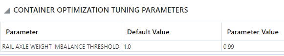
Tuning Parameter for Axle Balance.
Axle Weight Imbalance
The Axle Weight Imbalance is calculated as the ratio:
- Truck A Weight / Truck B Weight (if Truck A Weight is smaller)
- Truck B Weight / Truck A Weight (if Truck B Weight is smaller)
The imbalance ratio will always be between 0 and 1.0.
Rail Axle Weights Status
The Container Optimization logic parameter RAIL AXLE WEIGHT IMBALANCE THRESHOLD is used to set a new RAIL AXLE WEIGHTS status on the Shipment Equipment. The logic will set the status value based on the Shipment Equipment's Axle Weight Imbalance, the Shipment Equipment's Truck Axle Weights, and the Equipment Group's Maximum Axle Weight.
The possible status values are
- RAIL AXLE WEIGHT NOT CALCULATED ( Default Value when axle weights not calculated )
- RAIL AXLE WEIGHT FEASIBLE ( When calculated axles weights are within maximum allowed weight )
- RAIL AXLE WEIGHT FEASIBLE BUT IMBALANCED (When calculated axles weights are within maximum allowed weight but the imbalance ratio is more than defined threshold denoted by logic parameter "RAIL AXLE WEIGHT IMBALANCE THRESHOLD" )
- RAIL AXLE WEIGHT INFEASIBLE ( When calculated axles weights are more than the maximum axle weight)
NOTE: The axle weight calculation can be skipped in the below scenarios:
- If the Maximum Axle Weight on the equipment group is missing
- If the Truck Center Length on the equipment group is missing.
- If the Truck Count/Equipment Axle Count on the equipment group is missing.
- The logic will support the equipment groups with only 2 trucks. If you have more than 2 trucks, then the axle weight calculation will be skipped.
Packing Options – 3-D or Quick Pack with Column Generation
The enhancement works for 3-D packed loads since the position of each item is known. However, for the coil car that is packed by Quick Packing and Column Generation, the item positions are not known in the same manner, however there is an exception for the coil car.
This feature was added for a client that ships steel coils in cars that have permanently affixed cradles to hold the coils in a transverse position. OTM models this with the compartment. Compartment origins are configured with relationship to the equipment origin. OTM also assumes that the coils are perfectly centered in each compartment. This means that the “position” of each coil is known just like a 3-D placement of an item. This means that the same logic will apply.
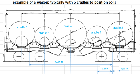
Rail Coil Car Schematic
This does require some internal math which is illustrated in the following diagram. This information is also helpful for the client to be able to configure the equipment correctly.
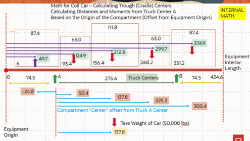
Rail Coil Car Moment DIstances
The diagram is added to show that the calculations of the “moments” which are the multiplication of the item weight and the distance to the Fulcrum point (which is highlighted in pink) are based on this transformation. The dimensions of the length of each compartment are at the top of each small box and this represents the width of the largest coil that will fit into a compartment. Some extra space, 6 inches, has been added onto each end to allow for a cover. The dimensions in the lower lefthand corner are the distances for the start of the compartment to the reference origin point of the equipment. The purple lines are the calculated distance to the center of the compartment. The light blue lines are the calculated moment distances. All that is needed to be configured are the compartments and truck related data.
When the bulk plan is done, the s-equipment will contain the calculations and the status code.
The calculation of Rail Axle Weights complements the existing calculation of the Center of Gravity which are two requirements for rail shippers, who must provide that information to the rail carriers for certain types of shipments.
Steps to Enable
The steps to enable are the configure the Equipment Group with the Truck Center Distance, the Equipment Truck Count, the Equipment Axle Count, and the Maximum Axle Weight. Then the threshold for the Imbalance is set as a Container Optimization Tuning Parameter.
If building shipments for steel coils in compartmentalized cars, then the equipment group and compartments must be well defined. If using 3-D, no extra configuration is needed. The calculations will be done if the data fields are populated.
Tips And Considerations
The Axle Weights are based on the summation of moments around the truck centers while the Center of Gravity. The client does not need to perform the transformation calculations as the logic handles that task. It is very important to define the equipment length for the coil steel equipment with respect to symmetry. If space is allowed between the compartment ends and the equipment ends, it must be even. Please do not ignore this step.