Diagram Component Type
This feature provides an Enhanced Workbench Diagram Component Type which provides the ability to visualize your Network Details for a selected Network. The visualization provides and excellent overview of the defined network, including a the networks related nodes and the network's directional flow.
In the example below, the Diagram view shows a South East Asia network where the network supports moving product from a factory in Asia to a CFS and then onto a Port and from the Port onto four different regions. The Diagram tool provides you with a complete visual overview of the Network, and allows you to easily highlight the nodes and legs in involved to gather more information and insight into the network.
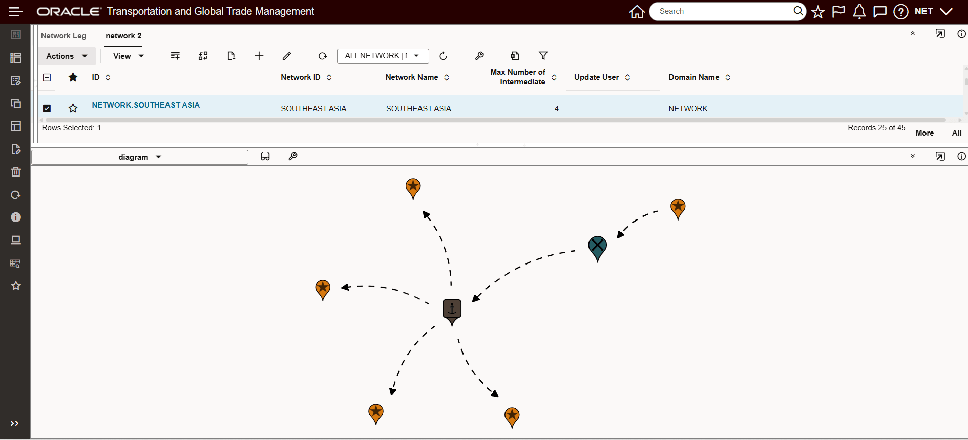
Simple Network Example South East Asia
Using the Detail Hover, you can hover over the nodes in the network to better understand the sources and destinations being represented for each leg.
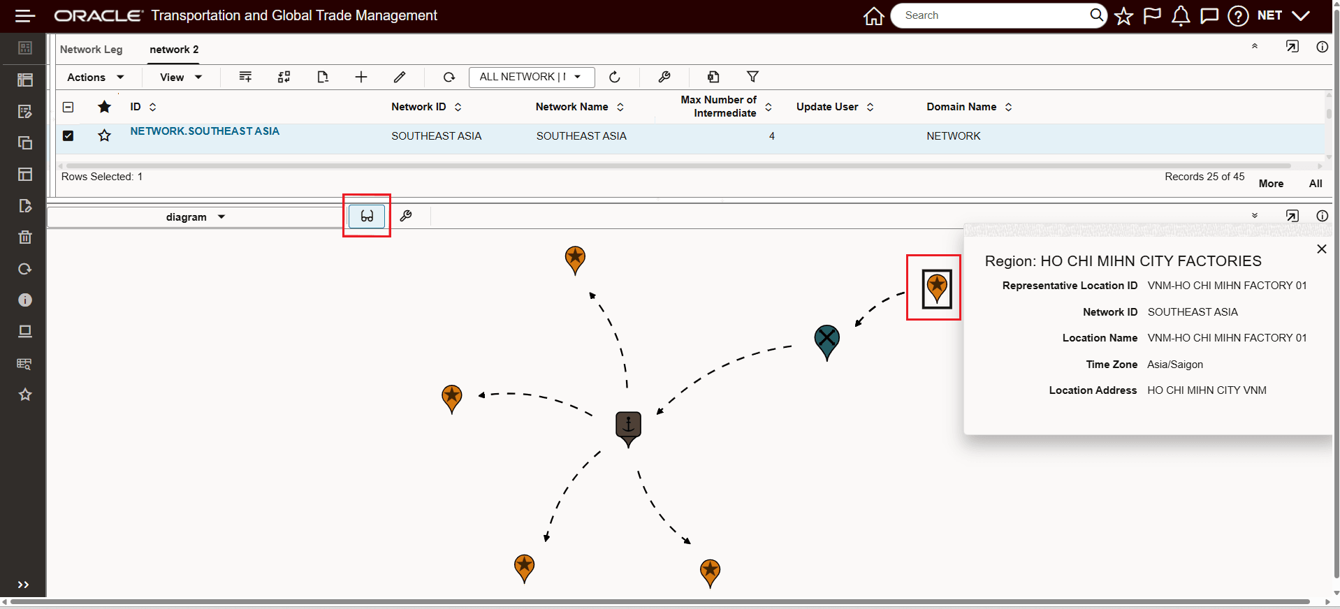
Detail Hover - Factory Source Location
In this network, freight moves from the factory above to the Container Freight Station (CFS) / Cross dock highlighted below.
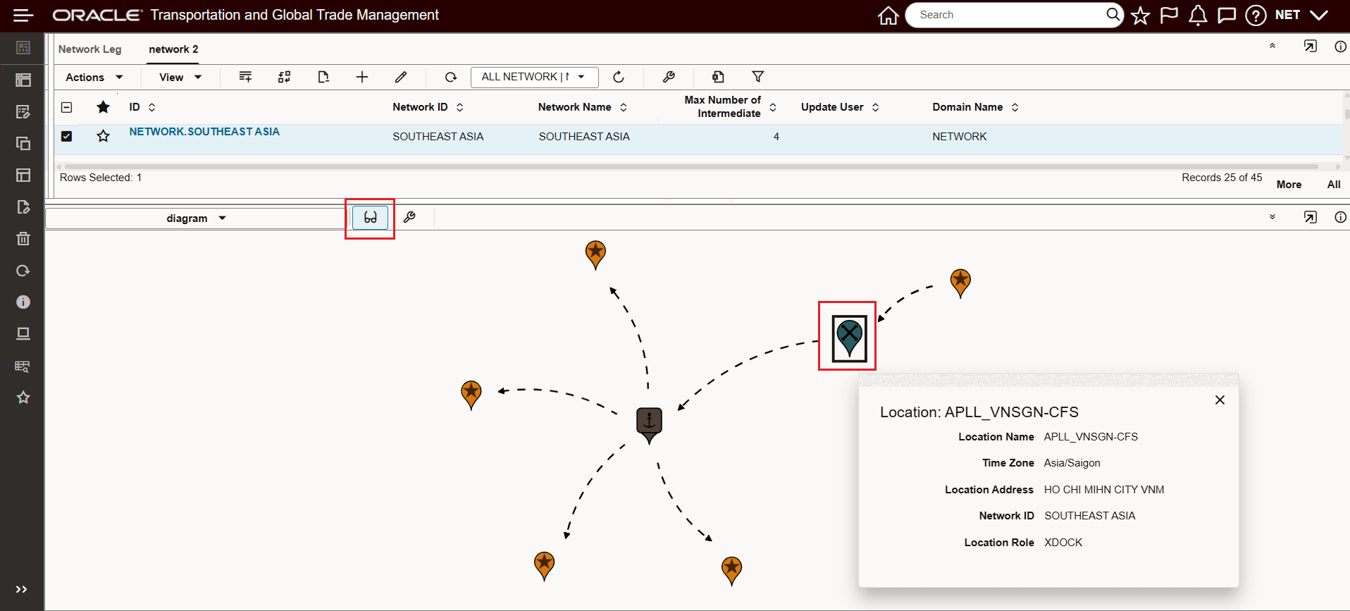
Detail Hover - Container Freight Station / Cross Dock
From the CFS, freight then moves to the Port and then from the Port to the Four Representative locations shown.
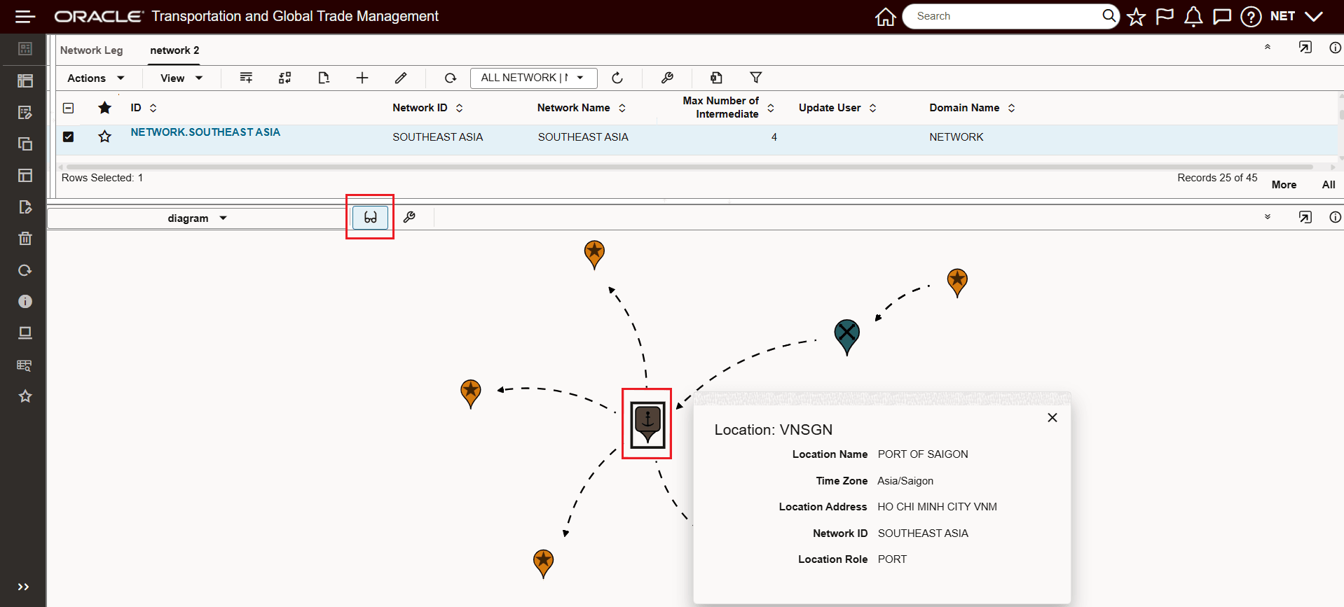
Detail Hover - Port
The Diagram tools becomes extremely useful as the complexity of your networks increases. In the example below, a more complex network with forty six network legs is used to demonstrate the Diagram tools capabilities and benefits.
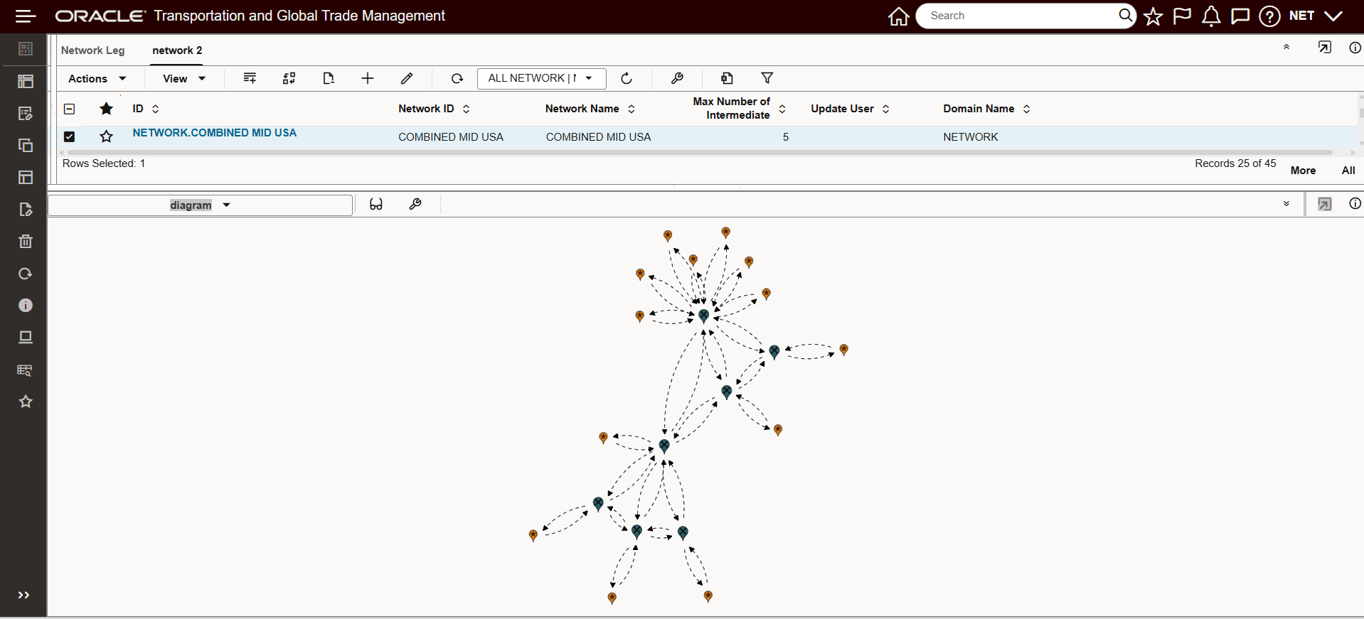
Larger Network Diagram Example
The Diagram component, also supports the ability to zoom into different portions of your networks to better understand how the network has been designed.
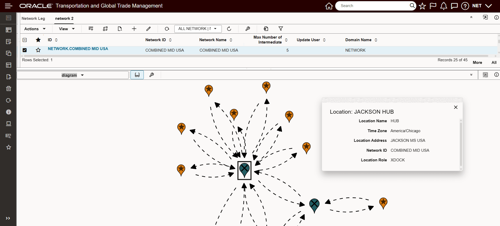
Zoom In Example With Hover Detail
Previously, the only option available for understanding your network configuration was to review the individual Network Details - shown below. The ability to visualize the network using the Diagram component (above) is considerably more intuitive for understanding the network supported configuration.
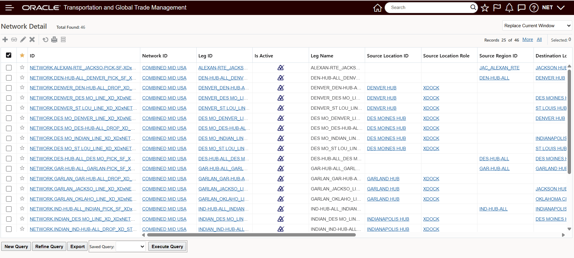
Network Detail
The Network visualization provided by the Diagram component, provides a comprehensive easy to understand view of your defined Network and related Network Details.
Steps to Enable and Configure
You don't need to do anything to enable this feature.
Tips And Considerations
The Diagram Parameters provide you with options to configure the view for Locations (Region Markers and Location Markers) and the Network (by Mode) for the lines displayed connecting the locations/regions in the network.
In the example below, the Locations Markers will be changed to show the Diagram Parameter Options.
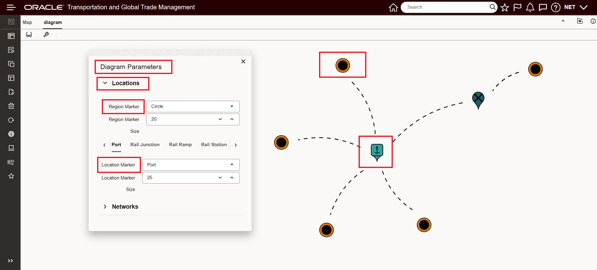
Diagram Parameters Locations
In this example, the Region Marker was changed from Circle to Teardrop and the Location Marker for Port was reduced sized.
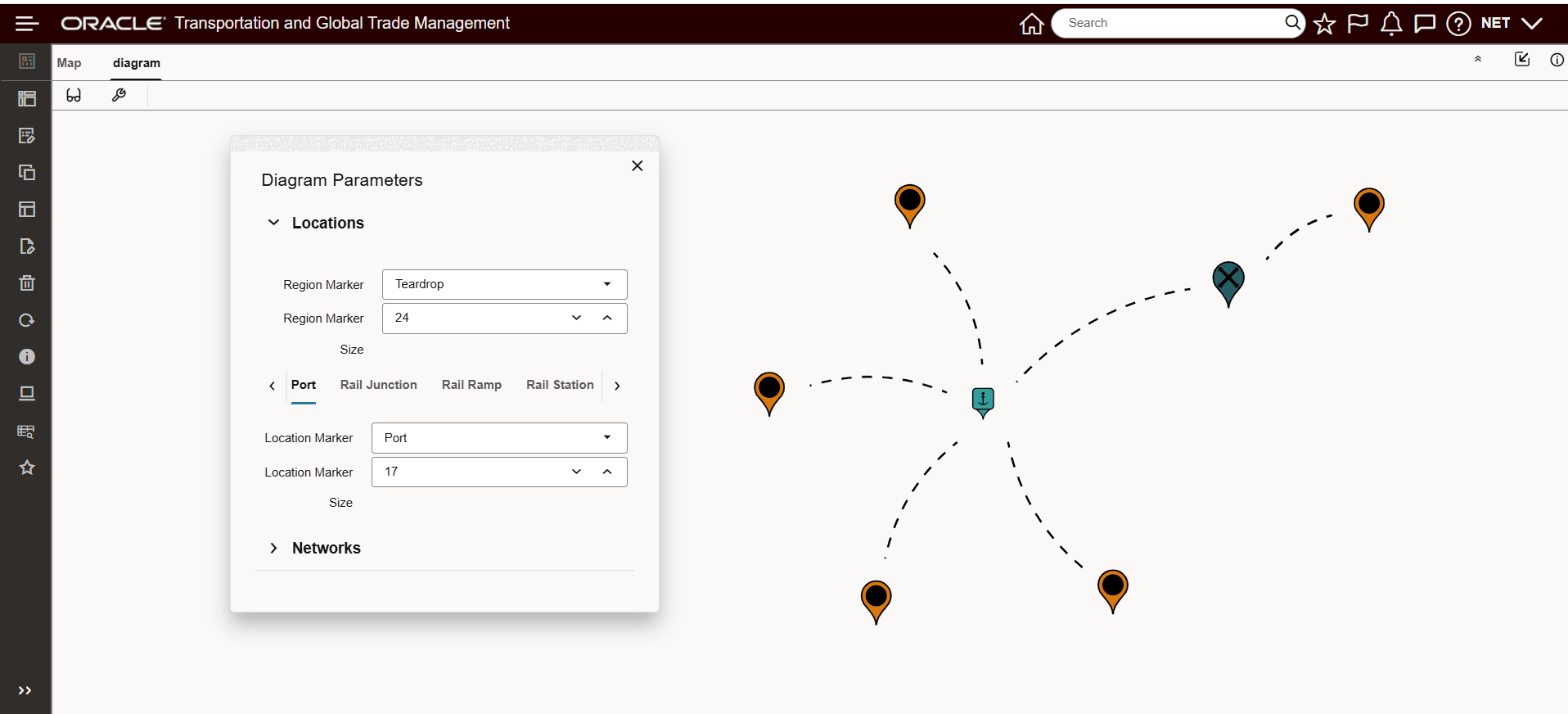
Diagram Parameters Locations Region Marker Changed, Location Marker Size Change
In the example below, the Networks options are shown. The Network options include selecting between Dashed or Solid line types - for Dashed you also have an option to animate the movement through the network. In addition to the Line Type (and width) there are several options for lines to be displayed with no arrows, end arrows or middle arrows or both. The options regarding lines are configurable by mode. In the example below TL is setup with Dashed Line, with Animation and with Show End Arrows selected..
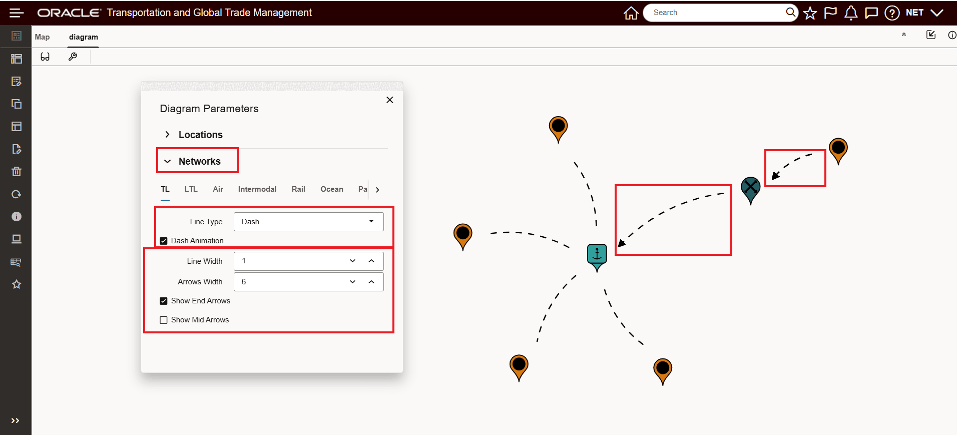
Networks Options Lines and Arrows by Mode
In the example below, the Ocean mode has been configured - the Line Type in this example is now Line (solid line) and both the Show End Arrows and Show Mid Arrows options have been selected.
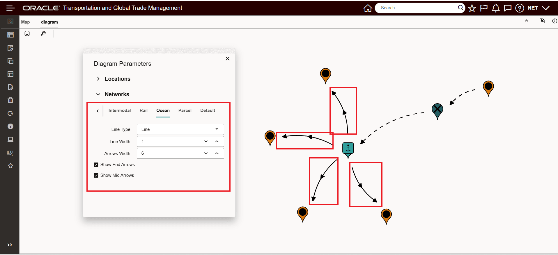
Networks Options Lines and Arrows by Mode - Ocean