7.5 LRS Operations
This topic describes several linear referencing operations supported by the Oracle Spatial LRS API.
- Defining a Geometric Segment
- Redefining a Geometric Segment
- Clipping a Geometric Segment (Dynamic Segmentation)
- Splitting a Geometric Segment
- Concatenating Geometric Segments
- Scaling a Geometric Segment
- Offsetting a Geometric Segment
- Locating a Point on a Geometric Segment
- Projecting a Point onto a Geometric Segment
- Converting LRS Geometries
Parent topic: Linear Referencing System
7.5.1 Defining a Geometric Segment
There are two ways to create a geometric segment with measure information:
-
Construct a geometric segment and assign measures explicitly.
-
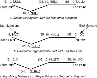
Define a geometric segment with specified start and end, and any other measures, in an ascending or descending order. Measures of shape points with unknown (unassigned) measures (null values) in the geometric segment will be automatically populated according to their locations and distance distribution.
Figure 7-8 shows different ways of defining a geometric segment:
An LRS segment must be defined (or must already exist) before any LRS operations can proceed. That is, the start, end, and any other assigned measures must be present to derive the location from a specified measure. The measure information of intermediate shape points will automatically be populated if measure values are not assigned.
Parent topic: LRS Operations
7.5.2 Redefining a Geometric Segment
You can redefine a geometric segment to replace the existing measures of all shape points between the start and end point with automatically calculated measures. Redefining a segment can be useful if errors have been made in one or more explicit measure assignments, and you want to start over with proportionally assigned measures.
Figure 7-9 shows the redefinition of a segment where the existing (before) assigned measure values are not proportional and reflect widely varying gaps.
After the segment redefinition in Figure 7-9, the populated measures reflect proportional distances along the segment.
Parent topic: LRS Operations
7.5.3 Clipping a Geometric Segment (Dynamic Segmentation)
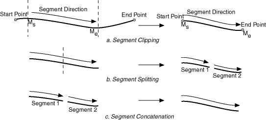
You can clip a geometric segment to create a new geometric segment out of an existing geometric segment, as shown in Figure 7-10, part a.
Figure 7-10 Clipping, Splitting, and Concatenating Geometric Segments
Description of "Figure 7-10 Clipping, Splitting, and Concatenating Geometric Segments"
In Figure 7-10, part a, a segment is created from part of a larger segment. The new segment has its own start and end points, and the direction is the same as in the original larger segment.
Clipping segments enables you to perform dynamic segmentation, where you clip the line at specific measure values. A scenario for such usage would be creating a table of road conditions, where for a given road, some segments are designated as in good condition and other segments are designated as in bad condition. For example, the segment between measures 100 and 120 might be in good condition, but the segment between measures 120 and 125 might be in poor condition. See the reference information for the synonymous functions SDO_LRS.CLIP_GEOM_SEGMENT and SDO_LRS.DYNAMIC_SEGMENT.
Parent topic: LRS Operations
7.5.4 Splitting a Geometric Segment
You can create two new geometric segments by splitting a geometric segment, as shown in the figure in Clipping a Geometric Segment (Dynamic Segmentation), part b. The direction of each new segment is the same as in the original segment.
Note:
In Clipping a Geometric Segment (Dynamic Segmentation) and other topics, small gaps between segments are used in illutrations of segment splitting and concatenation. Each gap simply reinforces the fact that two different segments are involved. However, the two segments (such as segment 1 and segment 2 in Clipping a Geometric Segment (Dynamic Segmentation), parts b and c) are actually connected. The tolerance (see Tolerance) is considered in determining whether or not segments are connected.
Parent topic: LRS Operations
7.5.5 Concatenating Geometric Segments
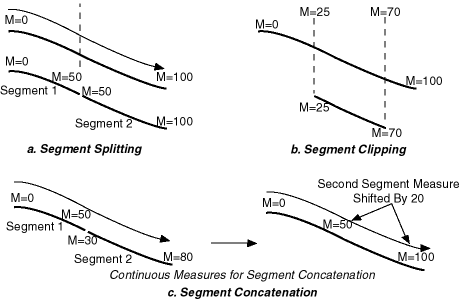
You can create a new geometric segment by concatenating two geometric segments, as shown in part c of the figure in Clipping a Geometric Segment (Dynamic Segmentation). The geometric segments do not need to be spatially connected, although they are connected in the illustration in part c of that figure. (If the segments are not spatially connected, the concatenated result is a multiline string.) The measures of the second geometric segment are shifted so that the end measure of the first segment is the same as the start measure of the second segment. The direction of the segment resulting from the concatenation is the same as in the two original segments.
Measure assignments for the clipping, splitting, and concatenating operations in the figure in Clipping a Geometric Segment (Dynamic Segmentation) are shown in the following figure. Measure information and segment direction are preserved in a consistent manner. The assignment is done automatically when the operations have completed.
Figure 7-11 Measure Assignment in Geometric Segment Operations
Description of "Figure 7-11 Measure Assignment in Geometric Segment Operations"
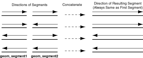
The direction of the geometric segment resulting from concatenation is always the direction of the first segment (geom_segment1 in the call to the SDO_LRS.CONCATENATE_GEOM_SEGMENTS function), as shown in the following figure.
Figure 7-12 Segment Direction with Concatenation
Description of "Figure 7-12 Segment Direction with Concatenation"
In addition to explicitly concatenating two connected segments using the SDO_LRS.CONCATENATE_GEOM_SEGMENTS function, you can perform aggregate concatenation: that is, you can concatenate all connected geometric segments in a column (layer) using the SDO_AGGR_LRS_CONCAT spatial aggregate function. (See the description and example of the SDO_AGGR_LRS_CONCAT spatial aggregate function in Spatial Aggregate Functions.)
Parent topic: LRS Operations
7.5.6 Scaling a Geometric Segment
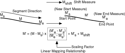
You can create a new geometric segment by performing a linear scaling operation on a geometric segment. Figure 7-13 shows the mapping relationship for geometric segment scaling.
In general, scaling a geometric segment only involves rearranging measures of the newly created geometric segment. However, if the scaling factor is negative, the order of the shape points needs to be reversed so that measures will increase along the geometric segment's direction (which is defined by the order of the shape points).
A scale operation can perform any combination of the following operations:
-
Translating (shifting) measure information. (For example, add the same value to Ms and Me to get M's and M'e.)
-
Reversing measure information. (Let M's = Me, M'e = Ms, and Mshift = 0.)
-
Performing simple scaling of measure information. (Let Mshift = 0.)
For examples of these operations, see the Usage Notes and Examples for theSDO_LRS.SCALE_GEOM_SEGMENT, SDO_LRS.TRANSLATE_MEASURE, SDO_LRS.REVERSE_GEOMETRY, and SDO_LRS.REDEFINE_GEOM_SEGMENT subprograms in SDO_LRS Package (Linear Referencing System) .
Parent topic: LRS Operations
7.5.7 Offsetting a Geometric Segment
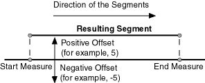
You can create a new geometric segment by performing an offsetting operation on a geometric segment. Figure 7-14 shows the mapping relationship for geometric segment offsetting.
Figure 7-14 Offsetting a Geometric Segment
Description of "Figure 7-14 Offsetting a Geometric Segment"
In the offsetting operation shown in Figure 7-14, the resulting geometric segment is offset by 5 units from the specified start and end measures of the original segment.
For more information, see the Usage Notes and Examples for the SDO_LRS.OFFSET_GEOM_SEGMENT function in SDO_LRS Package (Linear Referencing System) .
Parent topic: LRS Operations
7.5.8 Locating a Point on a Geometric Segment
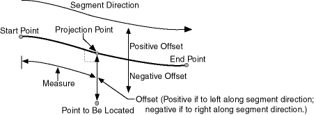
You can find the position of a point described by a measure and an offset on a geometric segment (see Figure 7-15).
Figure 7-15 Locating a Point Along a Segment with a Measure and an Offset
Description of "Figure 7-15 Locating a Point Along a Segment with a Measure and an Offset"
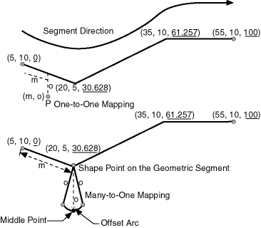
There is always a unique location with a specific measure on a geometric segment. Ambiguity arises when offsets are given and the points described by the measures fall on shape points of the geometric segment (see Figure 7-16).
Figure 7-16 Ambiguity in Location Referencing with Offsets
Description of "Figure 7-16 Ambiguity in Location Referencing with Offsets"
As shown in Figure 7-16, an offset arc of a shape point on a geometric segment is an arc on which all points have the same minimum distance to the shape point. As a result, all points on the offset arc are represented by the same (measure, offset) pair. To resolve this one-to-many mapping problem, the middle point on the offset arc is returned.
Parent topic: LRS Operations
7.5.9 Projecting a Point onto a Geometric Segment
You can find the projection point of a point with respect to a geometric segment. The point to be projected can be on or off the segment. If the point is on the segment, the point and its projection point are the same.
Projection is a reverse operation of the point-locating operation shown in Figure 7-15. Similar to a point-locating operation, all points on the offset arc of a shape point will have the same projection point (that is, the shape point itself), measure, and offset (see Figure 7-16). If there are multiple projection points for a point, the first one from the start point is returned (Projection Point 1 in both illustrations in Figure 7-17).
Parent topic: LRS Operations
7.5.10 Converting LRS Geometries
You can convert geometries from standard line string format to LRS format, and the reverse. The main use of conversion functions will probably occur if you have a large amount of existing line string data, in which case conversion is a convenient alternative to creating all of the LRS segments manually. However, if you need to convert LRS segments to standard line strings for certain applications, that capability is provided also.
Functions are provided to convert:
-
Individual line strings or points
For conversion from standard format to LRS format, a measure dimension (named M by default) is added, and measure information is provided for each point. For conversion from LRS format to standard format, the measure dimension and information are removed. In both cases, the dimensional information (DIMINFO) metadata in the USER_SDO_GEOM_METADATA view is not affected.
-
Layers (all geometries in a column)
For conversion from standard format to LRS format, a measure dimension (named M by default) is added, but no measure information is provided for each point. For conversion from LRS format to standard format, the measure dimension and information are removed. In both cases, the dimensional information (DIMINFO) metadata in the USER_SDO_GEOM_METADATA view is modified as needed.
-
Dimensional information (DIMINFO)
The dimensional information (DIMINFO) metadata in the USER_SDO_GEOM_METADATA view is modified as needed. For example, converting a standard dimensional array with X and Y dimensions (SDO_DIM_ELEMENT) to an LRS dimensional array causes an M dimension (SDO_DIM_ELEMENT) to be added.
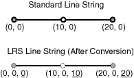
Figure 7-18 shows the addition of measure information when a standard line string is converted to an LRS line string (using the SDO_LRS.CONVERT_TO_LRS_GEOM function). The measure dimension values are underlined in Figure 7-18.
Figure 7-18 Conversion from Standard to LRS Line String
Description of "Figure 7-18 Conversion from Standard to LRS Line String"
For conversions of point geometries, the SDO_POINT attribute (described in SDO_POINT) in the returned geometry is affected as follows:
-
If a standard point is converted to an LRS point, the SDO_POINT attribute information in the input geometry is used to set the SDO_ELEM_INFO and SDO_ORDINATES attributes (described in SDO_ELEM_INFO and SDO_ORDINATES) in the resulting geometry, and the SDO_POINT attribute in the resulting geometry is set to null.
-
If an LRS point is converted to a standard point, the information in the SDO_ELEM_INFO and SDO_ORDINATES attributes (described in SDO_ELEM_INFO and SDO_ORDINATES) in the input geometry is used to set the SDO_POINT attribute information in the resulting geometry, and the SDO_ELEM_INFO and SDO_ORDINATES attributes in the resulting geometry are set to null.
The conversion functions are listed in SDO_LRS Package (Linear Referencing System) . See also the reference information in SDO_LRS Package (Linear Referencing System) about each conversion function.
Parent topic: LRS Operations
