1.2 Topology Data Model Concepts
Topology is a branch of mathematics concerned with objects in space. Topological relationships include such relationships as contains, inside, covers, covered by, touch, and overlap with boundaries intersecting.
Topological relationships remain constant when the coordinate space is deformed, such as by twisting or stretching. (Examples of relationships that are not topological include length of, distance between, and area of.)
The basic elements in a topology are its nodes, edges, and faces.
A node, represented by a point, can be isolated or it can be used to bound edges. Two or more edges meet at a non-isolated node. A node has a coordinate pair associated with it that describes the spatial location for that node. Examples of geographic entities that might be represented as nodes include start and end points of streets, places of historical interest, and airports (if the map scale is sufficiently large).
An edge is bounded by two nodes: the start (origin) node and the end (terminal) node. An edge has an associated geometric object, usually a coordinate string that describes the spatial representation of the edge. An edge may have several vertices making up a line string. (Circular arcs are not supported for topologies.) Examples of geographic entities that might be represented as edges include segments of streets and rivers.
The order of the coordinates gives a direction to an edge, and direction is important in determining topological relationships. The positive direction agrees with the orientation of the underlying edge, and the negative direction reverses this orientation. Each orientation of an edge is referred to as a directed edge, and each directed edge is the mirror image of its other directed edge. The start node of the positive directed edge is the end node of the negative directed edge. An edge also lies between two faces and has references to both of them. Each directed edge contains a reference to the next edge in the contiguous perimeter of the face on its left side.A face, corresponding to a polygon, has a reference to one directed edge of its outer boundary. If any island nodes or island edges are present, the face also has a reference to one directed edge on the boundary of each island. Examples of geographic entities that might be represented as faces include parks, lakes, counties, and states.
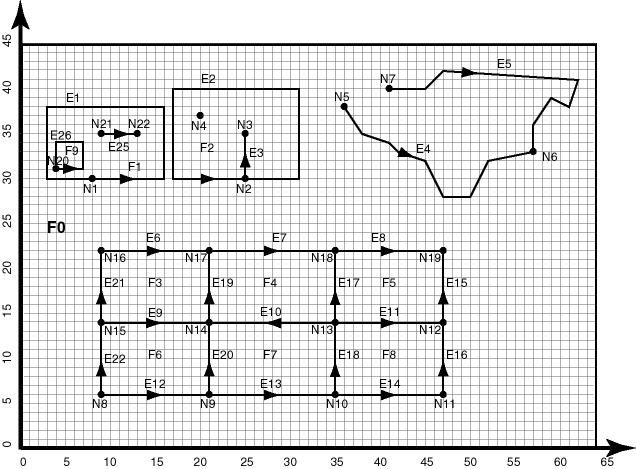
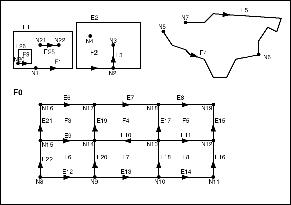
Figure 1-1 shows a simplified topology containing nodes, edges, and faces. The arrowheads on each edge indicate the positive direction of the edge (or, more precisely, the orientation of the underlying line string or curve geometry for positive direction of the edge).
Notes on Figure 1-1:
-
E elements (E1, E2, and so on) are edges, F elements (F0, F1, and so on) are faces, and N elements (N1, N2, and so on) are nodes.
-
F0 (face zero) is created for every topology. It is the universe face containing everything else in the topology. There is no geometry associated with the universe face. F0 has the face ID value of -1 (negative 1).
-
There is a node created for every point geometry and for every start and end node of an edge. For example, face F1 has only an edge (a closed edge), E1, that has the same node as the start and end nodes (N1). F1 also has edge E25, with start node N21 and end node N22.
-
An isolated node (also called an island node) is a node that is isolated in a face. For example, node N4 is an isolated node in face F2.
-
An isolated edge (also called an island edge) is an edge that is isolated in a face. For example, edge E25 is an isolated edge in face F1.
-
A loop edge is an edge that has the same node as its start node and end node. For example, edge E1 is a loop edge starting and ending at node N1.
-
An edge cannot have an isolated (island) node on it. The edge can be broken up into two edges by adding a node on the edge. For example, if there was originally a single edge between nodes N16 and N18, adding node N17 resulted in two edges: E6 and E7.
-
Information about the topological relationships is stored in special edge, face, and node information tables. For example, the edge information table contains the following information about edges E9 and E10. (Note the direction of the arrowheads for each edge.) The next and previous edges are based on the left and right faces of the edge.
For edge E9, the start node is N15 and the end node is N14, the next left edge is E19 and the previous left edge is -E21, the next right edge is -E22 and the previous right edge is E20, the left face is F3 and the right face is F6.
For edge E10, the start node is N13 and the end node is N14, the next left edge is -E20 and the previous left edge is E18, the next right edge is E17 and the previous right edge is -E19, the left face is F7 and the right face is F4.
For additional examples of edge-related data, including an illustration and explanations, see Edge Information Table.
Figure 1-2 shows the same topology illustrated in Figure 1-1, but it adds a grid and unit numbers along the x-axis and y-axis. Figure 1-2 is useful for understanding the output of some of the examples in SDO_TOPO Package Subprograms and SDO_TOPO_MAP Package Subprograms.
Figure 1-2 Simplified Topology, with Grid Lines and Unit Numbers

Description of "Figure 1-2 Simplified Topology, with Grid Lines and Unit Numbers"
1.2.1 Tolerance in the Topology Data Model
Tolerance is used to associate a level of precision with spatial data. Tolerance reflects the distance that two points can be apart and still be considered the same (for example, to accommodate rounding errors). The tolerance value must be a positive number greater than zero.
However, in the Topology Data Model, tolerance can have two meanings depending on the operation being performed: one meaning is the traditional Oracle Spatial definition of tolerance, and the other is a fixed tolerance value of 10E-15.
-
The tolerance value specified in the call to the SDO_TOPO.CREATE_TOPOLOGY procedure refers to the traditional Oracle Spatial definition, as explained in Oracle Spatial Developer's Guide. This value is used when indexes are created in the node, edge, and face tables, and when spatial operators are used to query these tables.
-
The tolerance value used for internal computations (for example, finding edge intersections) during topology editing operations is always 10E-15 (based on Java double precision arithmetic). This value is used during the validation checks performed by the SDO_TOPO_MAP.VALIDATE_TOPO_MAP and SDO_TOPO_MAP.VALIDATE_TOPOLOGY functions.
Thus, for example, an edge geometry that is considered valid by the SDO_TOPO_MAP.VALIDATE_TOPO_MAP or SDO_TOPO_MAP.VALIDATE_TOPOLOGY function might not be valid if that geometry is passed to the SDO_GEOM.VALIDATE_GEOMETRY_WITH_CONTEXT function.
Parent topic: Topology Data Model Concepts
