Topology Data Model Tables
To use the Oracle Spatial topology capabilities, you must first insert data into special edge, node, and face tables, which are created by Spatial when you create a topology.
The edge, node, and face tables are described in Edge Information Table, Node Information Table, and Face Information Table, respectively.
Spatial automatically maintains a relationship information (<topology-name>_RELATION$) table for each topology, which is created the first time that a feature table is associated with a topology (that is, at the first call to the SDO_TOPO.ADD_TOPO_GEOMETRY_LAYER procedure that specifies the topology). The relationship information table is described in Relationship Information Table.
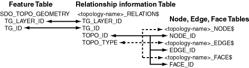
Figure: Mapping Between Feature Tables and Topology Tables shows the role of the relationship information table in connecting information in a feature table with information in its associated node, edge, or face table.
Figure: Mapping Between Feature Tables and Topology Tables
Description of the illustration feat_topo_rel.gif
As shown in Figure: Mapping Between Feature Tables and Topology Tables, the mapping between feature tables and the topology node, edge, and face tables occurs through the <topology-name>_RELATION$ table. In particular:
-
Each feature table includes a column of type SDO_TOPO_GEOMETRY. This type includes a TG_LAYER_ID attribute (the unique ID assigned by Oracle Spatial when the layer is created), as well as a TG_ID attribute (the unique ID assigned to each feature in a layer). The values in these two columns have corresponding values in the TG_LAYER_ID and TG_ID columns in the <topology-name>_RELATION$ table.
-
Each feature has one or more rows in the <topology-name>_RELATION$ table.
-
Given the TG_LAYER_ID and TG_ID values for a feature, the set of nodes, faces, and edges associated with the feature can be determined by matching the TOPO_ID value (the node, edge, or face ID) in the <topology-name>_RELATION$ table with the corresponding ID value in the <topology-name>_NODE$, <topology-name>_EDGE$, or <topology-name>_FACE$ table.
The following considerations apply to schema, table, and column names that are stored in any Oracle Spatial metadata views. For example, these considerations apply to the names of edge, node, face, relationship, and history information tables, and to the names of any columns in these tables and schemas for these tables that are stored in the topology metadata views described in Topology Metadata Views.
-
The name must contain only letters, numbers, and underscores. For example, the name cannot contain a space (
'), a quotation mark ("), or a comma (,). -
All letters in the names are converted to uppercase before the names are stored in metadata views or before the tables are accessed. This conversion also applies to any schema name specified with the table name.
Edge Information Table
You must store information about the edges in a topology in the <topology-name>_EDGE$ table, where <topology-name> is the name of the topology as specified in the call to the SDO_TOPO.CREATE_TOPOLOGY procedure. Each edge information table has the columns shown in Table: Columns in the <topology-name>_EDGE$ Table.
**Table: Columns in the
| Column Name | Data Type | Description |
|---|---|---|
| EDGE_ID | NUMBER | Unique ID number for this edge |
| START_NODE_ID | NUMBER | ID number of the start node for this edge |
| END_NODE_ID | NUMBER | ID number of the end node for this edge |
| NEXT_LEFT_EDGE_ID | NUMBER | ID number (signed) of the next left edge for this edge |
| PREV_LEFT_EDGE_ID | NUMBER | ID number (signed) of the previous left edge for this edge |
| NEXT_RIGHT_EDGE_ID | NUMBER | ID number (signed) of the next right edge for this edge |
| PREV_RIGHT_EDGE_ID | NUMBER | ID number (signed) of the previous right edge for this edge |
| LEFT_FACE_ID | NUMBER | ID number of the left face for this edge |
| RIGHT_FACE_ID | NUMBER | ID number of the right face for this edge |
| GEOMETRY | SDO_GEOMETRY | Geometry object (line string) representing this edge, listing the coordinates in the natural order for the positive directed edge |
The NEXT_LEFT_EDGE_ID and NEXT_RIGHT_EDGE_ID values refer to the next directed edges in the counterclockwise delineation of the perimeters of the left and right faces, respectively. The PREV_LEFT_EDGE_ID and PREV_RIGHT_EDGE_ID values refer to the previous directed edges in the counterclockwise delineation of the perimeters of the left and right faces, respectively. The LEFT_FACE_ID value refers to the face to the left of the positive directed edge, and the RIGHT_FACE_ID value refers to the face to the left of the negative directed edge. For any numeric ID value, the sign indicates which orientation of the target edge is being referred to.
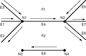
Figure: Nodes, Edges, and Faces shows nodes, edges, and faces that illustrate the relationships among the various ID columns in the edge information table. (In Figure: Nodes, Edges, and Faces, thick lines show the edges, and thin lines with arrowheads show the direction of each edge.)
Figure: Nodes, Edges, and Faces
Description of the illustration edge_table.gif
Table: Edge Table ID Column Values shows the ID column values in the edge information table for edges E4 and E8 in Figure: Nodes, Edges, and Faces. (For clarity, Table: Edge Table ID Column Values shows ID column values with alphabetical characters, such as E4 and N1; however, the ID columns actually contain numeric values only, specifically the numeric ID value associated with each named object.)
Table: Edge Table ID Column Values
| EDGE_ID | START_NODE_ID | END_NODE_ID | NEXT_LEFT_EDGE_ID | PREV_LEFT_EDGE_ID | NEXT_RIGHT_EDGE_ID | PREV_RIGHT_EDGE_ID | LEFT_FACE_ID | RIGHT_FACE_ID |
|---|---|---|---|---|---|---|---|---|
| E4 | N1 | N2 | -E5 | E3 | E2 | -E6 | F1 | F2 |
| E8 | N4 | N3 | -E8 | -E8 | E8 | E8 | F2 | F2 |
In Figure: Nodes, Edges, and Faces and Table: Edge Table ID Column Values:
-
The start node and end node for edge E4 are N1 and N2, respectively. The next left edge for edge E4 is E5, but its direction is the opposite of edge E4, and therefore the next left edge for E4 is stored as -E5 (negative E5).
-
The previous left edge for edge E4 is E3, and because it has the same direction as edge E4, the previous left edge for E4 is stored as E3.
-
The next right face is determined using the negative directed edge of E4. This can be viewed as reversing the edge direction and taking the next left edge and previous left edge. In this case, the next right edge is E2 and the previous right edge is -E6 (the direction of edge E6 is opposite the negative direction of edge E4). For edge E4, the left face is F1 and the right face is F2.
-
Edges E1 and E7 are neither leftmost nor rightmost edges with respect to edge E4, and therefore they do not appear in the edge table row associated with edge E4.
Node Information Table
You must store information about the nodes in a topology in the <topology-name>_NODE$ table, where <topology-name> is the name of the topology as specified in the call to the SDO_TOPO.CREATE_TOPOLOGY procedure. Each node information table has the columns shown in Table: Columns in the <topology-name>_NODE$ Table.
**Table: Columns in the
| Column Name | Data Type | Description |
|---|---|---|
| NODE_ID | NUMBER | Unique ID number for this node |
| EDGE_ID | NUMBER | ID number (signed) of the edge (if any) associated with this node |
| FACE_ID | NUMBER | ID number of the face (if any) associated with this node |
| GEOMETRY | SDO_GEOMETRY | Geometry object (point) representing this node |
For each node, the EDGE_ID or FACE_ID value (but not both) must be null:
-
If the EDGE_ID value is null, the node is an isolated node (that is, isolated in a face).
-
If the FACE_ID value is null, the node is not an isolated node, but rather the start node or end node of an edge.
Face Information Table
You must store information about the faces in a topology in the <topology-name>_FACE$ table, where <topology-name> is the name of the topology as specified in the call to the SDO_TOPO.CREATE_TOPOLOGY procedure. Each face information table has the columns shown in Table: Columns in the <topology-name>_FACE$ Table.
**Table: Columns in the
| Column Name | Data Type | Description |
|---|---|---|
| FACE_ID | NUMBER | Unique ID number for this face |
| BOUNDARY_EDGE_ID | NUMBER | ID number of the boundary edge for this face. The sign of this number (which is ignored for use as a key) indicates which orientation is being used for this boundary component (positive numbers indicate the left of the edge, and negative numbers indicate the right of the edge). |
| ISLAND_EDGE_ID_LIST | SDO_LIST_TYPE | Island edges (if any) in this face. (The SDO_LIST_TYPE type is described in SDO_LIST_TYPE Type.) |
| ISLAND_NODE_ID_LIST | SDO_LIST_TYPE | Island nodes (if any) in this face. (The SDO_LIST_TYPE type is described in SDO_LIST_TYPE Type.) |
| MBR_GEOMETRY | SDO_GEOMETRY | Minimum bounding rectangle (MBR) that encloses this face. (This is required, except for the universe face.) The MBR must be stored as an optimized rectangle (a rectangle in which only the lower-left and the upper-right corners are specified). The SDO_TOPO.INITIALIZE_METADATA procedure creates a spatial index on this column. |
Relationship Information Table
As you work with topological elements, Spatial automatically maintains information about each object in <topology-name>_RELATION$ tables, where <topology-name> is the name of the topology and there is one such table for each topology. Each row in the table uniquely identifies a topology geometry with respect to its topology geometry layer and topology. Each relationship information table has the columns shown in Table: Columns in the <topology-name>_RELATION$ Table.
**Table: Columns in the
| Column Name | Data Type | Description |
|---|---|---|
| TG_LAYER_ID | NUMBER | ID number of the topology geometry layer to which the topology geometry belongs |
| TG_ID | NUMBER | ID number of the topology geometry |
| TOPO_ID | NUMBER | For a topology that does not have a topology geometry layer hierarchy: ID number of a topological element in the topology geometry For a topology that has a topology geometry layer hierarchy: Reserved for Oracle use |
| TOPO_TYPE | NUMBER | For a topology that does not have a topology geometry layer hierarchy: 1 = node, 2 = edge, 3 = face For a topology that has a topology geometry layer hierarchy: Reserved for Oracle use |
| TOPO_ATTRIBUTE | VARCHAR2 | Reserved for Oracle use |
History Information Table
The history information table for a topology contains information about editing operations that are not recorded in other information tables. Thus, the history information table is not a comprehensive record of topology modifications. Instead, it contains rows for node, edge, or face editing operations only when one or more feature tables are associated with the topology and any of the following conditions are met:
-
An existing face or edge is split as a result of the operation.
-
A single face or edge is created by merging two faces or two edges as a result of the operation.
Spatial automatically maintains information about these operations in <topology-name>_HISTORY$ tables, where <topology-name> is the name of the topology and there is one such table for each topology. Each row in the table uniquely identifies an editing operation on a topological element, although an editing operation (such as using the SDO_TOPO_MAP.ADD_POLYGON_GEOMETRY function) can add multiple rows. (Topology editing is discussed in Editing Topologies .) Each history information table has the columns shown in Table: Columns in the <topology-name>_HISTORY$ Table.
**Table: Columns in the
| Column Name | Data Type | Description |
|---|---|---|
| TOPO_TX_ID | NUMBER | ID number of the transaction that was started by a call to the SDO_TOPO_MAP.LOAD_TOPO_MAP function or procedure or to the loadWindow or loadTopology Java method. Each transaction can consist of several editing operations. You can get the transaction ID number for the current updatable TopoMap object by calling the SDO_TOPO_MAP.GET_TOPO_TRANSACTION_ID function. |
| TOPO_SEQUENCE | NUMBER | Sequence number assigned to an editing operation within the transaction |
| TOPOLOGY | VARCHAR2 | ID of the topology containing the objects being edited |
| TOPO_ID | NUMBER | ID number of a topological element in the topology geometry |
| TOPO_TYPE | NUMBER | Type of topological element: 1 = node, 2 = edge, 3 = face |
| TOPO_OP | VARCHAR2 | Type of editing operation that was performed on the topological element: I for insert or D for delete |
| PARENT_ID | NUMBER | For an insert operation, the ID of the parent topological element from which the current topological element is derived; for a delete operation, the ID of the resulting topological element |
Consider the following examples:
-
Adding a node to break edge E2, generating edge E3: The TOPO_ID value of the new edge is the ID of E3, the TOPO_TYPE value is 2, the PARENT_ID value is the ID of E2, and the TOPO_OP value is
I. -
Deleting a node to merge edges E6 and E7, resulting in E7: The TOPO_ID value is the ID of E6, the TOPO_TYPE value is 2, the PARENT_ID value is the ID of E7, and the TOPO_OP value is
D.
To further illustrate the effect of editing operations on the history information table, a test procedure was created to perform various editing operations on a simple topology, and to examine the effect on the history information table for the topology. The procedure performed these main steps:
-
It created and initialized a non-geodetic topology with a universe face, and added a line feature layer and an area feature layer to the topology.
-
It created a rectangular area by adding four isolated nodes and four edges connecting the isolated nodes. This caused a face (consisting of the rectangle) to be created, and it caused one row to be added to the history information table: an insert operation for the new face, whose parent is the universe face.
The following statement shows the history information table row added by this insertion:
SELECT topo_id, topo_type, topo_op, parent_id FROM hist_test_history$ ORDER BY topo_tx_id, topo_sequence, topology; TOPO_ID TOPO_TYPE TOP PARENT_ID ---------- ---------- --- ---------- 1 3 I -1 1 row selected. -
It split the rectangular face into two smaller rectangular faces (side-by-side) by adding two nodes and a vertical edge connecting these nodes, which caused two edges (the top and bottom edges) and the face to be split. Three rows were added to the history information table: an insert operation for each of the two new edges (with the parent of each new edge being the existing edge that was split), and an insert operation for the new face (whose parent is the original rectangular face that was split).
The following statement shows the history information table rows added thus far. The rows added by this step are shown in bold:
SELECT topo_id, topo_type, topo_op, parent_id FROM hist_test_history$ ORDER BY topo_tx_id, topo_sequence, topology; TOPO_ID TOPO_TYPE TOP PARENT_ID ---------- ---------- --- ---------- 1 3 I -1 6 2 I 2 7 2 I 4 2 3 I 1 4 rows selected. -
It added a diagonal edge to small rectangular face on the left (using the existing nodes), and it removed the vertical edge that was added in Step 3. Two rows were added to the history information table: an insert operation for the new face created as a result of the edge addition (with the parent of each new face being the small rectangular face on the left that was split), and a delete operation as a result of the edge removal (with the resulting face taking its topological object ID from one of the “parent” faces that were merged).
The following statement shows the history information table rows added thus far. The rows added by this step are shown in bold:
SELECT topo_id, topo_type, topo_op, parent_id
  FROM hist_test_history$ ORDER BY topo_tx_id, topo_sequence, topology;

   TOPO_ID  TOPO_TYPE TOP  PARENT_ID

---------- ---------- --- ----------
         1          3 I           -1
         6          2 I            2
         7          2 I            4
         2          3 I            1

         3          3 I            2

         1          3 D            2

6 rows selected.