3 Using Oracle Spatial Studio

Using Oracle Spatial Studio, you can create one or more projects, each of which can define one or more spatial datasets on which you can perform various spatial operations.

It is important you understand the following terminologies when working on Spatial Studio:

  • A project contains Spatial Studio objects, such as datasets, that are logically related to some intended usage. For example, a project might be named New England Sales Territories, or Sales Territories and Customers, or Ohio Airports and Counties. When creating a project, you should know the purposes for which you want to identify and analyze spatial data in a geographic area.
  • A dataset is a collection of spatial features of a specific usage type and geometry type. For example, datasets might include Airports represented by polygon geometries, or Roadways represented by LRS line string geometries, or Accidents represented by point geometries.
  • A connection specifies information for connecting to an Oracle Database schema where spatial data of interest resides: user name, password, system, port, database name, and so on. (It is similar to a SQL Developer connection.)

Note:

See also Spatial Studio Terminology for more information.

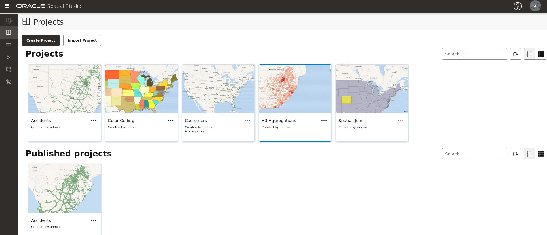
The main landing page for Spatial Studio for a new user is as shown:

Figure 3-1 Spatial Studio Main Page

Description of Figure 3-1 follows
Description of "Figure 3-1 Spatial Studio Main Page"

The overall layout of the Spatial Studio user interface comprises of:

  • Header: The header at the top of the page contains the following buttons:
    • toggle_menu: to display or hide the side navigation menu
    • help_icon : to help you get started on Spatial Studio by providing an overview of the tool and links to other tutorial resources
    • avatar: displays the user profile details
  • Side Navigation Menu: A navigation panel on the left displays the menu items. You can expand or collapse the navigation drawer.
  • User Workspace: The page specific details for the selected menu option is displayed on the right.

The navigation menu consists of the following menu options:

  • Active Project: Directs you to the Active Project page where your recent working project is displayed.
  • Projects: Directs you to the Projects page where all your existing projects and published projects are listed.
  • Datasets: Directs you to the Datasets page where all the datasets available to you are listed.
  • Connections: Directs you to the Connections page where all the existing connections (data sources) available to you are listed.
  • Jobs: Directs you to the Jobs page where the various background jobs started by Spatial Studio to process various requests are listed.
  • Administration: Directs you to the Administration page where you can monitor the status and activity of Spatial Studio. It contains tabs for Settings, Maintenance, and Monitoring.

3.1 Logging in to Spatial Studio

Once you have installed Spatial Studio, either as a standalone tool (Quick Start) or as a Java EE deployment, you can log in to the application.

To log in to Spatial Studio:
  1. Launch Spatial Studio in your browser using the URL provided for your installation.

    For example, if you are using the Quick Start deployment, then open the URL, https://localhost:4040/spatialstudio, in your browser.

    Spatial Studio login page appears as shown:

    Figure 3-2 Spatial Studio Login Page

    Description of Figure 3-2 follows
    Description of "Figure 3-2 Spatial Studio Login Page"
  2. Enter the User Name.
  3. Enter the Password.
  4. Select your preferred language to be used in Spatial Studio from the Language drop-down list.
  5. Click Login.
    You are now logged in to Spatial Studio.

3.1.1 About Internationalization in Spatial Studio

Oracle Spatial Studio supports internationalization of its user interface.

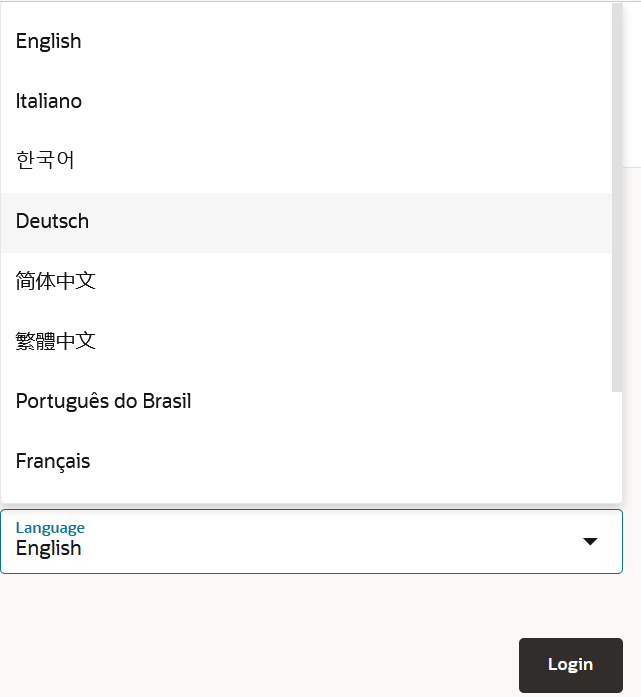
You can choose to adapt the Spatial Studio user interface to use one of the following supported languages when logging in to the application:
  • English (default)
  • German
  • Spanish
  • French
  • Italian
  • Japanese
  • Korean
  • Portuguese-BR
  • Simplified Chinese
  • Traditional Chinese

Figure 3-3 Internationalization Support in Spatial Studio
Description of Figure 3-3 follows
Description of "Figure 3-3 Internationalization Support in Spatial Studio"

Note, however, any server generated messages or errors will continue to be displayed in English. If you want to switch to a different language after logging in, then you must first log out and select the required language when logging in again.

In case you have configured Spatial Studio to use IDCS as the login provider, then there is no explicit language selector. This is because the login dialog belongs to IDCS. In this case, Spatial Studio will check the locale and language settings in your IDCS profile, and use that to automatically select the best matched language from the list of supported languages. For instance, if your IDCS profile has Canadian French set as the preferred language, then Spatial Studio will use French to display its UI as it does not support Canadian French.

3.2 Getting Started Using Spatial Studio

Spatial Studio includes a page with information and links to help you get started using the tool.

To display this page, click the small question mark icon (?) in the top right area of most pages (above the Create button) and click Getting Started from the context menu.

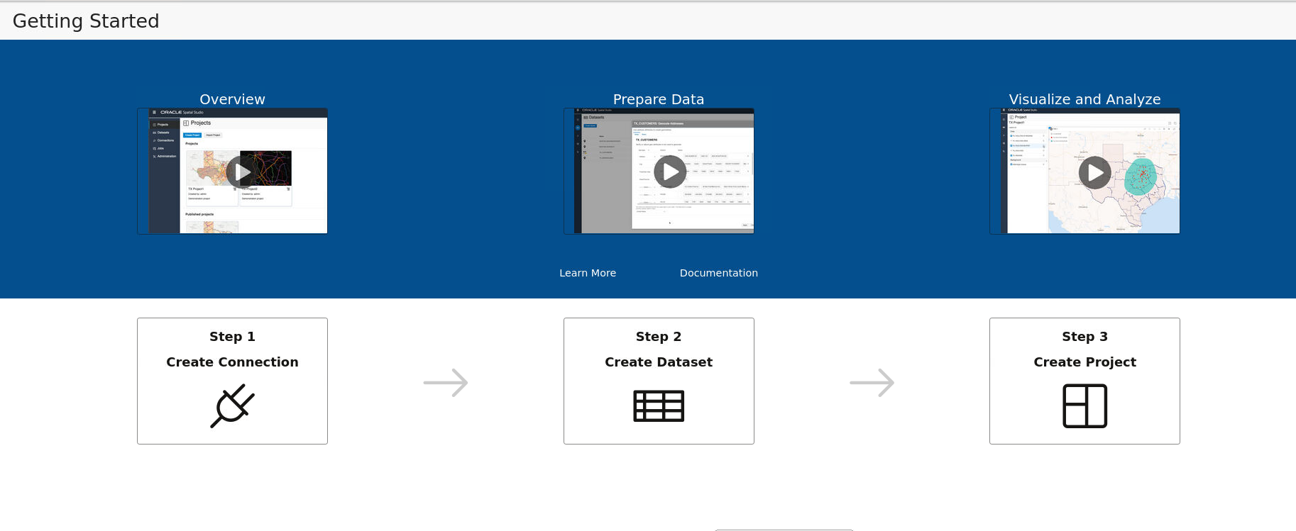
The Getting Started page opens as shown:

Figure 3-4 Getting Started Page

Description of Figure 3-4 follows
Description of "Figure 3-4 Getting Started Page"

You can learn more about Spatial Studio by clicking one of the following options:

  • Overview: Watch this video to understand the user interface and see how to perform the available actions.
  • Prepare Data: Enable your business data for mapping and spatial analysis.
  • Visualize and Analyze: Explore geographic patterns and relationships in your business data.
  • Learn More: Visit our video library to learn more about Oracle Spatial Cloud.
  • Documentation: See Oracle Spatial Studio Guide documentation to learn more about administering and using Spatial Studio.
  • Get started using Spatial Studio through the following workflow:
    1. Step1 - Create Connection: Begin by creating your database connection.
    2. Step2 - Create Dataset: Create a Dataset and load spatial data.
    3. Step3 - Create Project: Create a Project for visualizing and analyzing the spatial data.

3.3 Generating an Access Token

You can generate an access token to access REST endpoints of Spatial Studio.

Spatial Studio supports two types of tokens:
  • General-purpose token: Full access to all resources. The token grants read-only or read-write access as required.
  • Streaming-only token: Access only to REST endpoints related to dataset streaming. Also, the token grants read-only access that be used only with HTTP GET methods.
To generate an access token:
  1. Click avatar on the top right corner of the page.
  2. Click Access Tokens from the drop-down menu.
    The Access Tokens dialog opens and the existing tokens are displayed.
  3. Click Create New Token.
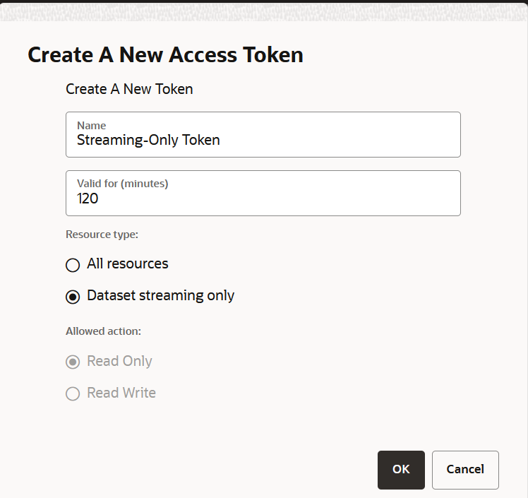
    Create A New Access Token dialog opens as shown:

    Figure 3-5 Creating a New Access Token

    Description of Figure 3-5 follows
    Description of "Figure 3-5 Creating a New Access Token"
  4. Enter the token Name.
  5. Enter the time Valid for (minutes) after which the token expires.
    If you specify -1, then Spatial Studio will never expire the token, unless you explicitly revoke it.
  6. Select Resource type.
  7. Optionally, select the Allowed action for granting access to a general-purpose token.
  8. Click OK to create the token.
    The token gets created successfully.

3.4 Spatial Studio Active Project Page

The Active Project page displays your current working project.

You can switch to your working project at any time from the other pages when working in Spatial Studio.

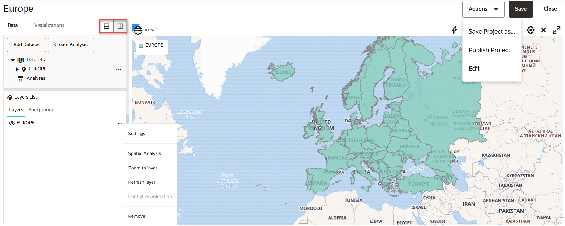
The following figure shows a layout of the Active Project page:

You can perform the following actions on the Active Project page:
  • Creating a table or map visualization.
  • Adding or removing datasets from your project.
  • Adding or removing data from a visualization layer.
  • Organizing the Layers List panel to be arranged vertically below or to the right of the project Data and Visualizations panel using the icons shown highlighted in the preceding figure.
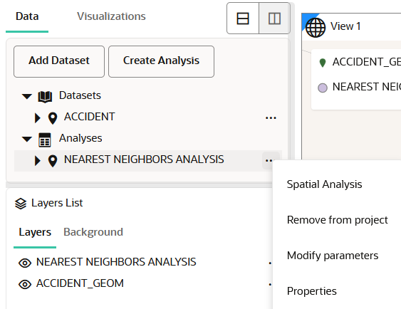
  • Adjusting the style setting or the zoom resolution for your visualization layer. You can click the menu selector next to the map layer in the Layers tab to display the following available options:
    • Settings: Shows display options for Style, Filter, Interaction, and Legend.
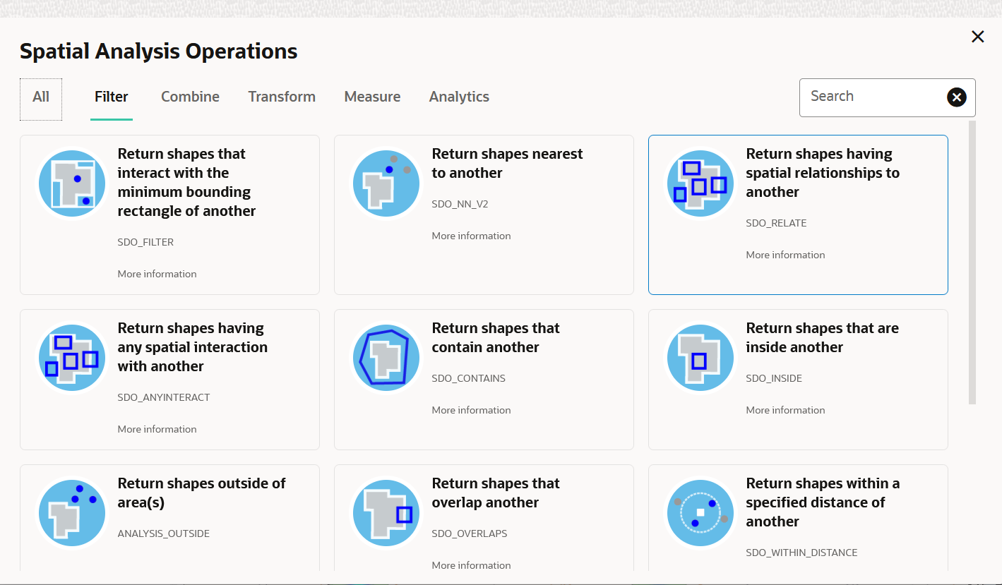
    • Spatial Analysis: Allows you to perform many spatial operations (All, or filtered by type: Filter, Combine, Transform, Measure), such as Add a buffer of a specified distance, Return shapes having spatial relationship to another, and Calculate area.
    • Zoom to Layer: Zooms the display (out or in) to fit the entire layer.
    • Refresh Layer: Refreshes the layer to reflect all user actions.
    • Configure Animation: Allows you to configure animation settings to visualize a moving object.
    • Remove: Removes the layer from the project.
  • Using the project management options displayed on the top-right area of the Active Project page:
    • Actions: The drop-down menu allows you to:
      • Save Project as: Creates a new copy of the project.
      • Publish Project: Publishes the project.
      • Edit: Allows you to edit the project details (such as, Name, Created By and Description).
    • Save: Saves your updates to the project.
    • Close: Closes the project.

3.5 Spatial Studio Projects Page

The Projects page lists all the projects that have been created, both unpublished and published.

Figure 3-1 shows the layout of the Projects page.

You can perform the following actions on the Projects page:

  • You can select a project to work or for viewing the details.
  • You can create a new project by clicking Create Project.
  • You can import a project by clicking Import and selecting a project zip file in the Import Project dialog.
  • You can open, export or delete a project by clicking the additional_options_icon icon for any of the listed projects.
  • You can alter the display settings to have the projects listed as cards or in a tabular format.
  • You can search for both unpublished and published projects.

Note:

For the first two actions, the project will be opened in the Active Project page.

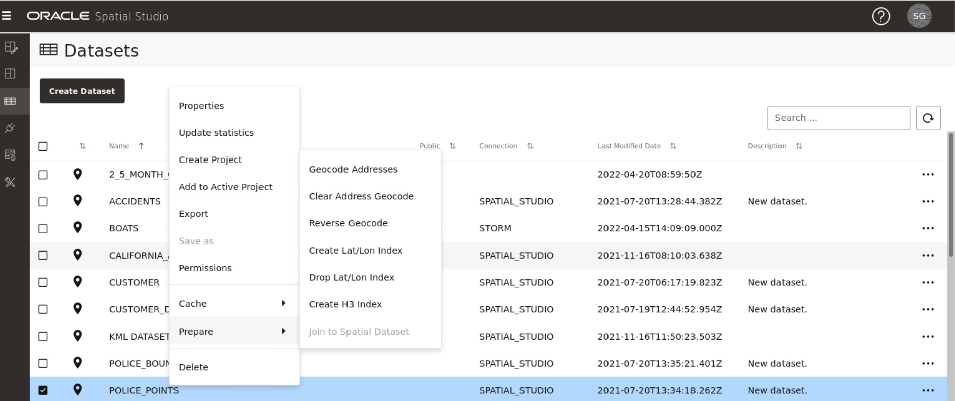
3.6 Spatial Studio Datasets Page

The Datasets page lets you view and edit existing datasets, and create new ones.

The following figure shows the Datasets page:

You can perform the following actions on the Datasets page:

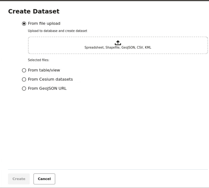
  • You can create a new dataset, by clicking Create Dataset.

    You can create a dataset from the following sources:

    • Oracle Database table or view using a database connection
    • By uploading dataset files with different formats to the database, such as :
      • Spreadsheet file
      • Shapefile
      • GeoJSON file
      • CSV file
      • KML file
    • By importing 3D Tiles Tileset

By clicking additional_options_icon against any displayed dataset or by right-clicking a dataset row, you can perform the following actions :

  • Properties: View or modify properties of the dataset
  • Update Statistics: Update the dataset statistics
  • Create Project: Create a new project using the dataset
  • Add to Active Project: Add the dataset to the project in the Active Project page
  • Export: Export the dataset (in GeoJSON or CSV file format)
  • Save as: Make a new copy of the dataset
  • Permissions: Configure dataset sharing and permissions
  • Cache: Control map tiles pre-caching activities
  • Prepare: Prepare a dataset for any of the following options:
    • Geocode Addresses: Add geocoded information such as geographic coordinates to the dataset
    • Clear Address Geocode: Remove geocoded information from the dataset
    • Reverse Geocode: Add address information from a set of geographic coordinates to the dataset
    • Create Lat/Lon Index: Create latitude/longitude index
    • Drop Lat/Lon Index: Remove latitude/longitude index
    • Create H3 Index: Prepare an H3 aggregation dataset
    • Join to Spatial Dataset: Prepare a non-spatial dataset for map visualization by joining to a spatial dataset
  • Delete: Delete the dataset

3.6.1 Creating a Dataset

The following steps enable you to add a new dataset.
  1. Navigate to the Datasets page.
  2. Click Create Dataset.
    The Create Dataset window opens:
  3. Click on one of the data source options and perform the steps appropriate to your selection as shown in the following:
    From file upload:
    1. Upload one of the supported file types.
    2. Click Create.

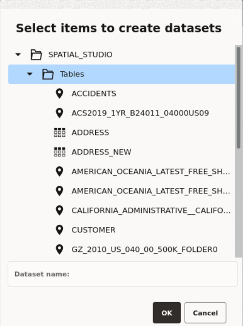
    From table/view:

    1. Select a connection from the Select Connection drop-down.
    2. Click Create.

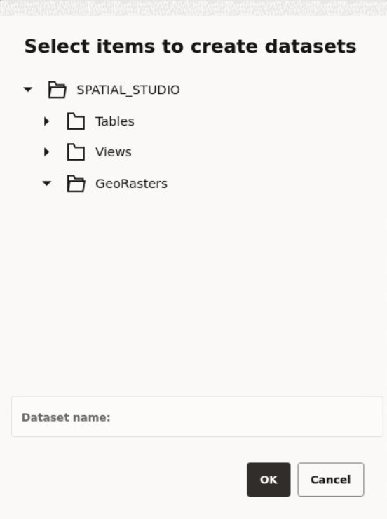
      The Select items to create datasets window opens listing all the tables, views and GeoRaster data present in the database.

      Figure 3-9 Select the Data Source

      Description of Figure 3-9 follows
      Description of "Figure 3-9 Select the Data Source"
    3. Select an item from the list and click OK.
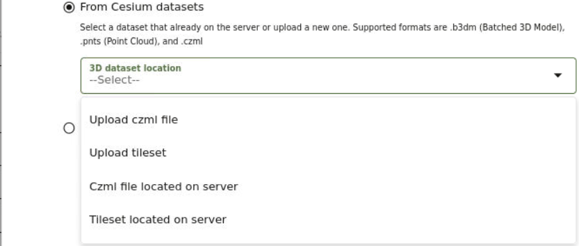
    From Cesium datasets:
    1. Create a dataset for Cesium map visualization by selecting a 3D dataset file or a CZML file.

      Figure 3-10 Options for Creating a Cesium Dataset

      Description of Figure 3-10 follows
      Description of "Figure 3-10 Options for Creating a Cesium Dataset"

      You can choose one of the following options:

      • Upload czml file: Upload a .czml file.
      • Upload tileset: Upload a tileset zip file. The supported formats are:
        • .b3dm: Batched
        • .pnts: Point Cloud

        Tip:

        You can increase the default size limit for zip files larger than 50 MB by updating the dataset_max_size attribute for the upload property defined in <user_home_folder>/.sgtech/sgtech_config.json file.
      • Czml file located on server: Specify the czml file to be uploaded from the server by entering the Name of the .czml file and the Directory path.
      • Tileset located on server: Specify the tileset file to be uploaded from the server by entering the Name of the tileset.json file and the Directory path.

      Note:

      When uploading a CZML file or a tileset file from the server:
      • If the file is not under <SGTECH_HOME>/cesiumdata or <SGTECH_HOME>/3d-tilesets as it may apply, then you must manually migrate the datasets when migrating Spatial Studio.
      • You can update the unzipped file limits in the General tab in the Administration page. The following two advanced settings parameters need to be modified:
        • Maximum unzipped item
        • Maximum unzipped total
    2. Click Create.

    From GeoJSON URL:

    It is important to note the following prior to creating a GeoJSON URL dataset:

    • A GeoJSON URL based dataset accesses its data directly from the source URL. There is no database table managed in Spatial Studio for this dataset.
    • A GeoJSON URL based dataset does not support Spatial Analysis.
    • A GeoJSON URL based dataset is subject to the same upload size limit, or 100MB, whichever is smaller.
    • If a GeoJSON URL does not support CORS (Cross-Origin Resource Sharing), then Spatial Studio will act as a proxy to the browser requesting the GeoJSON URL data.

    The following steps enable you to create a GeoJSON URL dataset:

    1. Specify the GeoJSON URL to access GeoJSON data from an external domain for map visualization.

      Note:

      Ensure you add the external domain used for accessing GeoJSON data to the list of entries in the Safe Domains list.
    2. Click Create.

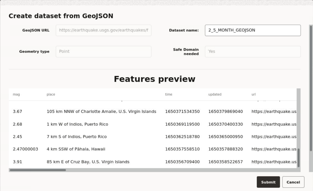
      Create dataset from GeoJSON window opens as shown:

      Figure 3-11 Creating a Dataset from GeoJSON

      Description of Figure 3-11 follows
      Description of "Figure 3-11 Creating a Dataset from GeoJSON"
    3. Optionally, enter a Dataset name.
    4. Click Submit.

      The GeoJSON URL dataset gets created with the warning, No key column was found. You must resolve the warning in order to use the dataset as a map layer for visualization. See Datasets with Issues for more details to resolve the warning.

    The new dataset is added and listed on the Datasets page.

3.6.1.1 Uploading a Shapefile

You can create a dataset by uploading a shapefile.

A shapefile contains the geospatial data which can be referenced in multiple files with specific file extensions. The following lists a few selected files that contribute to shapefile format:
  • .shp - Stores the geometry data
  • .shx - Stores the index of the geometry
  • .dbf - Stores the attribute information of geometry features
  • .prj - Stores the coordinate system information
  • .cpg - Specifies the character set to be used
  1. Navigate to the Datasets page and click Create Dataset.
    Create Dataset window opens as shown in Figure 3-8.
  2. Select From file upload.
  3. Click upload_icon to upload the shape file.
    The File Upload window opens.
  4. Select all the required files from your system.

    Note:

    It is mandatory to upload .shp, .shx, and .dbf files.

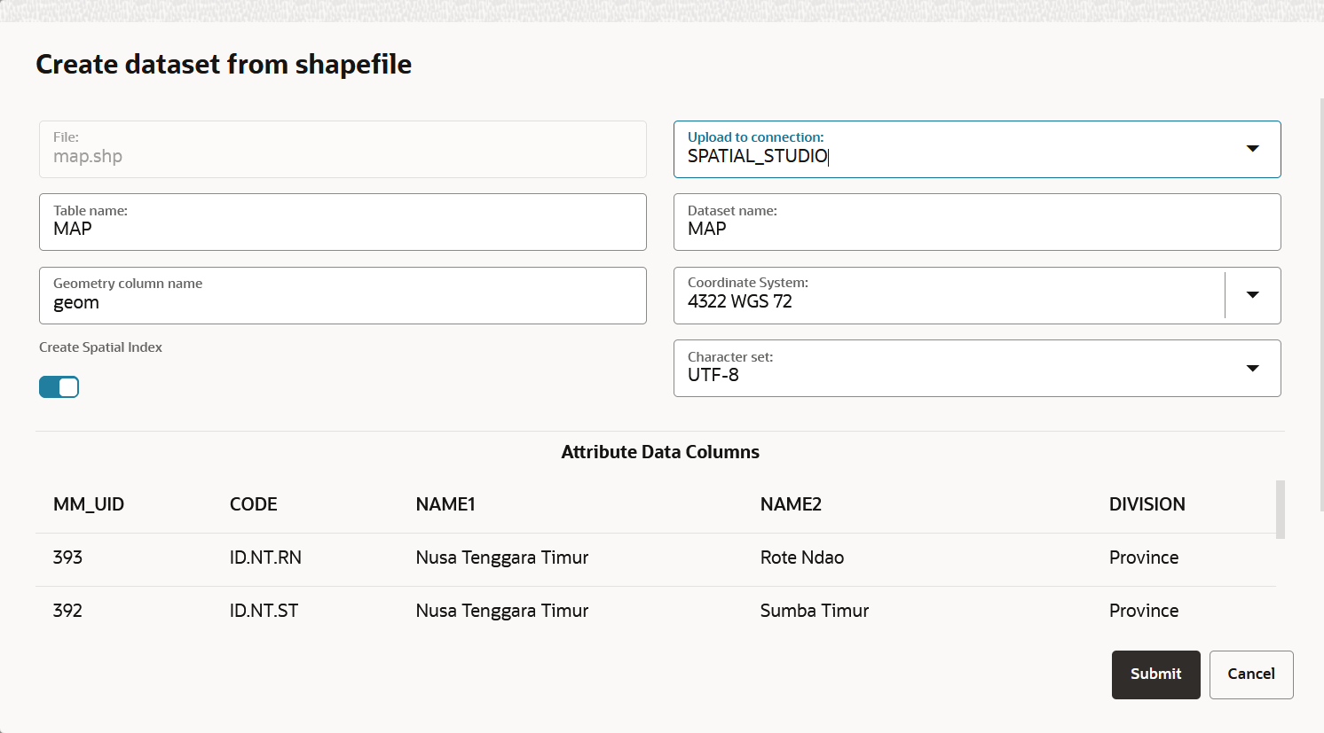
    The Create dataset from shapefile dialog opens as shown:

    Figure 3-12 Create dataset from shapefile

    Description of Figure 3-12 follows
    Description of "Figure 3-12 Create dataset from shapefile"
  5. Select the connection to upload the shapefile from the Upload to connection drop-down list.
  6. Optionally, change the Table name.
  7. Optionally, change the destination Dataset name.
  8. Optionally, select the Coordinate System to be used.
    • If your shapefile includes a .prj file referencing a custom Geographic Coordinate System (GEOGCS), then Spatial Studio will assign a best-matched geodetic SRID from the target Spatial database, as shown in the preceding figure.
    • If your shapefile does not contain a .prj file, then the system uses the default EPSG:4326 GEOGCS.
  9. Optionally, select the required Character set.
    Spatial Studio automatically detects the character set to be used in the following order of priority:
    • Extracts the charset-name from a .cpg file, if present.
    • Uses the character set specified in the .dbf file header.
    • Otherwise, uses the default ISO-8859-1.

    You can preview the file attributes using the detected character set. However, you can still choose to switch to a different Character set and preview the refreshed contents.

  10. Click Submit.
    The dataset gets created from a shapefile.

3.6.2 Datasets with Issues

All datasets must meet certain data requirements in order to be used for map visualization and analysis. Otherwise, Spatial Studio highlights these datasets with a warning on the Datasets page.

You may click on the warning icon to view the issues. You can then click on the resolution link under the issue to prepare the dataset as required for analysis, as shown:

Figure 3-13 Warnings on a Dataset

Description of Figure 3-13 follows
Description of "Figure 3-13 Warnings on a Dataset"
The following table lists a few common issues that are highlighted on a dataset.

Table 3-1 Selected List of Dataset Issues

Issue Cause Spatial Studio Resolution
No key column was found Primary key is missing on the dataset.
  • Click Go to Dataset Columns to create a dataset key.

    The Dataset Properties configuration window opens.

  • Select a column containing unique values and switch ON Use as Key.
  • Click Validate key.
  • Click Apply.
This dataset needs spatial metadata and index The geometry column in the dataset does not have the spatial metadata or a spatial index or both. Click Create Spatial Metadata and Index to create the spatial metadata and index for the geometry column.
Preparation Required for mapping and spatial analysis It can be due to one of the following reasons:
  • The dataset contains address information but the geographic coordinates are missing.
  • Latitude and Longitude index are missing for latitude/longitude data in the dataset.
Depending on the cause, you may need to perform one of the following:
  • Click Geocode Addresses
  • Click Create Latitude/Longitude Index
3.6.2.1 Enabling Spatial on a View-Based Dataset with Latitude and Longitude Columns
Spatial Studio allows you to create spatial index on a dataset created from a view containing latitude and longitude columns, thereby enabling you to visualize and analyze views.
The following steps enable you to create latitude/longitude index on a view-based dataset.

The instructions assume:

  • You have created a dataset from a view having latitude and longitude columns.

    See Creating a Dataset for more information on creating a dataset from a view.

  • This view-based dataset is listed on the Datasets page with a warning icon since the dataset is not spatially enabled for visualization.
  1. Navigate to the Datasets page.
  2. Click on the warning icon to view the issues on the view-based dataset.
  3. Click Create Latitude/Longitude Index.
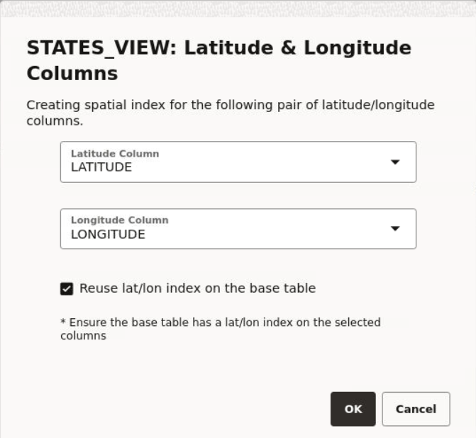
    The Latitude and Longitude Columns window opens as shown:

    Figure 3-14 Creating a Latitude/Longitude Index on a View-Based Dataset

    Description of Figure 3-14 follows
    Description of "Figure 3-14 Creating a Latitude/Longitude Index on a View-Based Dataset"
  4. Select the Latitude Column.
  5. Select the Longitude Column.
  6. Select the Reuse lat/lon index on the base table checkbox.
    As displayed in the preceding figure, ensure that the base table on which the view is created has a spatial index on the latitude and longitude columns.
  7. Click OK.
    A background task of type Create lon-lat index gets executed. A successful completion of this task on the Jobs page indicates that the dataset is spatially enabled for visualization.

    You can now use this view-based dataset for visualization on the Active Project page.

3.6.3 Geocoding a Dataset

Geocoding is the process of deriving the latitude and longitude coordinates from location details that are geo address types.

You can geocode a dataset in Spatial Studio to store the resulting latitude and longitude information as a SDO_GEOMETRY column. Optionally, you can also store them in a latitude and longitude numeric columns in the underlying database table referenced by the dataset.

Prior to geocoding a dataset, if the Spatial Studio server is running behind a firewall, then ensure you have the correct Web Proxy information configured in the Administration page. This is because the Spatial Studio application uses an external Oracle hosted geocoding service which is on the public internet.

You can perform the following steps to geocode a dataset.

The instructions assume that a dataset containing location columns such as address details is already existing in Spatial Studio .
  1. Navigate to the Datasets page.
  2. Right-click on the dataset name on which you want to apply geocoding.
    Ensure that the dataset has a valid key column defined.
  3. Select Geocode Addresses from the Prepare context menu.
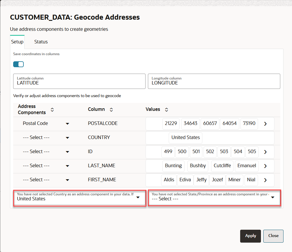
    Geocode Addresses dialog opens as shown:
  4. Click Setup tab.
  5. Select the Geo-type for the geo-attributes to be used for geocoding.
    You must provide sufficient geographic data for successful geocoding. If the address components do not include the country or state attributes, then you must explicitly select either the country or the state in the respective drop-down list shown highlighted in the preceding figure.
  6. Optionally, switch ON Save coordinates in columns to save the geocoordinates to the dataset and to the underlying database table.
  7. Optionally, enter Latitude column name and Longitude column name, if you switched ON Save coordinates in columns in the preceding step.
  8. Click Apply.
    The geocoding process gets initiated and can be monitored on the Jobs page. Also, note the following:
    • The geocoding process is performed in batches and the default batch size is 50. At any time, you can change the default geocoding batch size under the General settings in the Administration page.
    • If any batch fails, the overall geocoding job will not fail. You will be notified on the failed batch at the end of job completion.
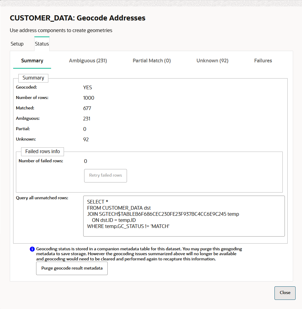
    • At the end of the geocoding process, you can view the results in the Status tab as shown:
    • On successful completion of a geocoding job, you can verify that geocoding has been applied by viewing the latitude and longitude columns in the dataset properties and in the input source database table along with the GC_GEOMETRY column of data type SDO_GEOMETRY.

3.6.4 Reverse Geocoding a Dataset

Reverse geocoding is the process of deriving the address information from a set of latitude and longitude coordinates.

You can reverse geocode a dataset in Spatial Studio to add address information to the dataset's table using the following steps.

Note:

Reverse Geocoding is supported only in point or latitude and longitude datasets.
The instructions assume that a dataset containing the coordinates details is already existing in your database schema.
  1. Navigate to the Datasets page.
  2. Right-click on the dataset name on which you want to apply reverse geocoding.
  3. Select Reverse Geocode from the Prepare context menu.
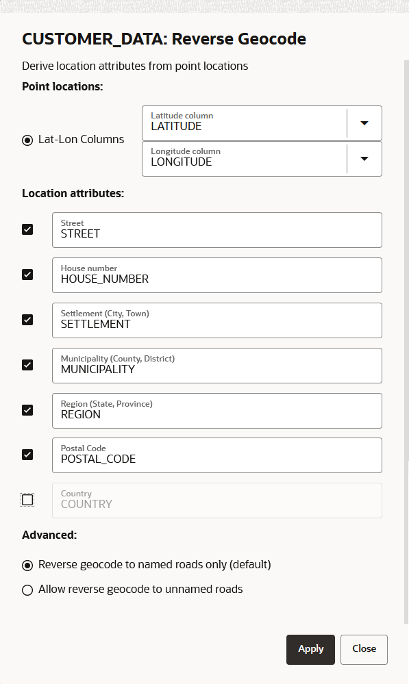
  4. Optionally, select and modify the required Location attributes as shown in Figure 3-17.
    The Input text fields for Location attributes are the column names to be created in the underlying database table for the target dataset.
  5. Select the Advanced option as required.
    The default Reverse geocode to named roads only option ensures that for all latitude and longitude coordinates that do not match a named road, the closest street or road name will be obtained while geocoding.
  6. Click Apply.
    You can monitor the Reverse geocode dataset background task on the Jobs page. A successful completion of the job indicates that reverse geocoding is applied for the data in the dataset.
    You can verify that reverse geocoding has been applied to your dataset by viewing the additional address related columns in the dataset properties.

3.6.5 Preparing a Non-Spatial Dataset for Analysis

Spatial Studio allows you to prepare a non-spatial dataset for mapping and analysis by joining to a spatial dataset.

Also, note the following highlights about joining two datasets:

  • You can only join a non-spatial dataset to a spatial dataset and not conversely.
  • It is essential that the non-spatial data in one dataset is linked to the spatial data in the other dataset through a common primary key column.
  • You can choose the columns for the newly created joined dataset from the attributes of the datasets associated in the join operation.
The instructions assume that a spatial dataset and a non-spatial dataset having a common primary key data is already existing in your database schema.
  1. Navigate to the Datasets page.
  2. Right-click on the non-spatial dataset which you want to join to a spatial dataset.
  3. Select Join to Spatial Dataset from the Prepare context menu.
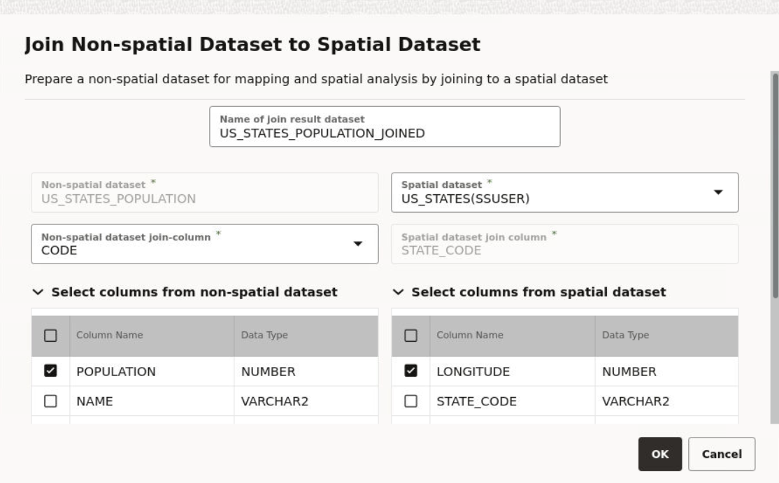
    The following window opens:

    Figure 3-18 Joining to a Spatial Dataset

    Description of Figure 3-18 follows
    Description of "Figure 3-18 Joining to a Spatial Dataset"
  4. Optionally, enter a dataset name for Name of join result dataset.
  5. Select the Spatial dataset for the join.
    On selection, the primary key associated with the spatial dataset is validated against the non-spatial dataset key. If the datasets key values are not suitable for a join operation, then the following error is displayed:
    Dataset key columns to join must be the same data type
  6. Optionally, select the required columns for the joined result dataset from the non-spatial and spatial datasets.
  7. Click OK.

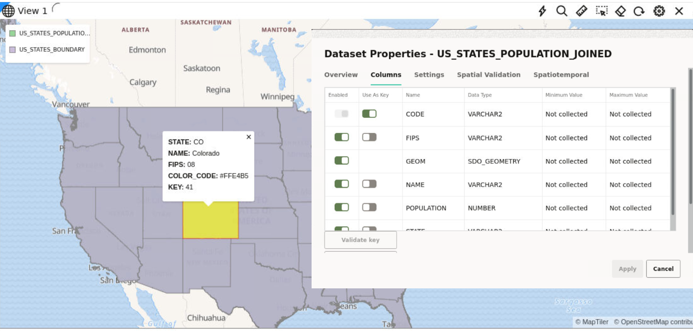
    The joined dataset is created and it appears as a row on the Datasets Page. This dataset will contain all the column properties selected from both the spatial and non-spatial datasets. You can verify the properties of the joined dataset both in the Dataset Properties window on the Datasets page and when using the dataset for map visualization and analysis on the Active Projects page, as shown:

    Figure 3-19 Appended Non-spatial and Spatial Properties

    Description of Figure 3-19 follows
    Description of "Figure 3-19 Appended Non-spatial and Spatial Properties"

3.7 Spatial Studio Connections Page

The Connections page displays all the existing connections and also allows you to create a new connection.

The following figure shows a layout of the Connections page:

You can perform the following actions on the Connections page:

  • You can create a new connection, by clicking Create Connection.

    You can create a connection from the following sources:

    • Oracle Database: by providing host, port, schema, and other database authentication details
    • Oracle Autonomous Database: by providing wallet details
  • You can also perform the following actions by clicking the hamburger icon against any displayed connection or by right-clicking a connection row :
    • Properties: View or modify properties of the connection
    • Edit: Update the connection details

      Note:

      You cannot edit the SPATIAL_STUDIO connection on the Connections page. Instead, refer to If the Spatial Studio Repository Schema Password Has Been Changed section.
    • Test: Validate the connection
    • Delete: Delete the connection along with all its datasets

      Note:

      You cannot delete the SPATIAL_STUDIO connection.

3.8 Spatial Studio Administration Page

You can monitor the status and activity of Spatial Studio in the Administration Page. You can also view server logs, change global system configurations, manage custom basemaps, and configure safe domains.

The Administration menu link directs you to the Administration page.

Note:

You must be logged in as an administrator of Spatial Studio to access this menu option.
The layout the Administration page is as shown:

Figure 3-21 Administration Page

Description of Figure 3-21 follows
Description of "Figure 3-21 Administration Page"
The Studio console page comprises of the following sections:

Settings

  • General: This section allows changing the GeoCoding service URL, the geocoding batch size, and the web proxy used by the Studio server. It also allows you to customize the frontend branding area of the application.
  • Safe Domains: This section allows the administrator to manage the white listing of the domains (host names or IP addresses) that are considered safe for loading various types of the resources from the Studio application. Typically, it is used to add the domain of a custom basemap to the Content Security Policy directives of the Studio. After making the changes to the safe domains list, you must reload or refresh the browser page to reload the new Content Security Policy.
  • Basemaps: This section allows a quick view of the existing custom basemaps, and in adding or editing custom basemaps. Custom basemaps can be made of either raster or vector tiles, typically hosted on a third party tile server. Additionally, you can also create a custom basemap using a WMS OGC web service.
  • Cesium Basemaps: This section gives you a quick view of the existing custom basemaps used exclusively for the 3D Cesium Map visualization. It also allows you to add new basemaps to be used by the 3D Map visualizations.

Note:

Each listed host entry for Basemaps and Cesium Basemaps must be present as one of the entries in the Safe Domains list. If the host basemap comes from a domain that is not present in the Safe Domains list, then the basemap may not render correctly when visualizing the map.

Maintenance

  • Refresh Coordinate System cache: Use this only when needed to rebuild the text index of the repository database schema’s supported Spatial Reference Well Known Text (WKText) definitions. For the shapefile upload, this WKText index is used to automatically match the best SRID.
  • Refresh Metadata Cache: Spatial Studio typically caches all of the frequently used metadata such as the definitions of Datasets, Connections, and Projects. Sometimes it is required to refresh the whole cache in case some cached metadata becomes stale or out of sync in rare events.

Monitoring

  • Server Status: This section provides read-only information about the general health and system status of the Spatial Studio server.
  • Cache Status: This section provides the details of the cache maintained by Spatial Studio.
  • Service Logs: This section allows loading and viewing a desired number of server-side logs. To reduce the clutter, you can filter the result using the desired logging level .

In a cluster deployment, both the preceding options display only the information of the particular Spatial Studio instance to which the current session is connected.

3.8.1 Adding a Custom Basemap

The following steps enable you to add a custom basemap.

  1. Navigate to the Administration page.
  2. Click Basemaps under Settings.
    The Basemaps window listing all the available basemaps opens.
  3. Click Add Basemap and click on one of the following basemap types:
    • XYZ Raster tiles
    • OGC WMS
    • Vector tiles
  4. Enter Name and URL for the selected basemap type.
  5. Optionally enter Attribution and API Key.

    Tip:

    Once you have entered all the required fields, you can preview the basemap by clicking Quick View.
  6. Click Save to add the base map.
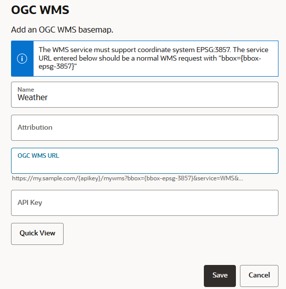
    For example, the following figure show the OGC WMS basemap configuration window:

    Figure 3-22 Adding a OGC WMS Map

    Description of Figure 3-22 follows
    Description of "Figure 3-22 Adding a OGC WMS Map"

    Note:

    It is important to add the domain name to Safe Domains in order to enable the Spatial Studio application to access the required service for the basemap.

3.8.2 Editing a Custom Basemap

The following steps enable you to edit a custom basemap.

  1. Navigate to the Administration page.
  2. Click Basemaps under Settings.
    The Basemaps window listing all the available basemaps opens.
  3. Click additional_options_icon against the required custom basemap and click Edit from the context menu.

    Note:

    Edit is disabled for predefined Spatial Studio maps.
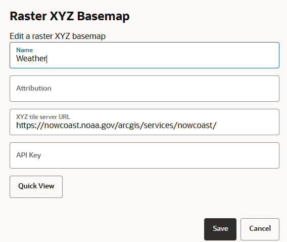
    The custom basemap configuration details are displayed for editing as shown:

    Figure 3-23 Editing a Custom Basemap

    Description of Figure 3-23 follows
    Description of "Figure 3-23 Editing a Custom Basemap"
  4. Modify the required parameters, such as Name, Attribution, URL or API Key.
  5. Click Save.
    The custom basemap details are modified and the updates are shown in the Basemaps window.

3.9 Spatial Studio Jobs Page

The Jobs page displays details of all the background jobs that run in Spatial Studio.

The following figure shows a layout of the Jobs page:

You can perform the following actions on the Jobs page:

  • Select a job to be displayed in the grid: Active, Past or All.
  • Select a refresh interval for the jobs grid.
  • View details of a specific job.
  • Terminate a job.

    Also, note the following about terminating a job:

    • You can terminate a Processing or Pending job.
    • You can terminate all job types except Create lon-lat index jobs.
    • Upon termination of a job, partial execution results of the job are maintained. You can choose to clear the partial results. For example, you can perform Clear Address Geocode after terminating a Geocode job.
    • Only jobs related to H3 aggregations such as Build H3 Index are completely rolled back when terminated.

The grid table displays the following properties for each job entry row:

  • Type: The job type, such as "Geocode", "Reverse geocode dataset" and so on.
  • Object: The entity being altered by the job, which can be a Dataset, Table, Index or other.
  • Created by: The user that submitted the job.

    Note:

    System maintenance jobs are created by “$system” account
  • Start Time: The scheduled next run time for jobs with Pending status or the actual job start time for any other job status.
  • End Time: The time at which a job completed.
  • Status: Indicates the state or progress of a job, which can be:
    • Pending
    • Processing
    • Done
    • Error
    • Terminating
    • Terminated

By clicking additional_options_icon against any job row, you can perform the following actions :

  • View Details: To view extra information, such as the step at which a Processing job is currently running or error details for Error or Terminated jobs. Also, you can terminate a Processing job by clicking Terminate when viewing the job details.
  • Terminate: To terminate a Processing or Pending job directly. It remains disabled for any other job status.

3.10 Visualization in Oracle Spatial Studio

You can visualize your spatial data in Oracle Spatial Studio using different modes of visualization.

Spatial Studio supports the following visualization methods:

  • Table
  • Map
  • Cesium-Map

You can save your visualization as a Project in Spatial Studio. You can rework on a project or publish a project to share the results with other users.

The following sections explain in detail how you can use the various visualization techniques:

3.10.1 Using a Table Visualization

Spatial Studio allows you to visualize your data from the dataset in tables.
To display your data in a tabular view, you must perform the following steps.
The instructions assume that the dataset for visualization is already added to the project in the Active Project page.
  1. Click the Visualizations tab on the left pane in the Active Project page.
    This lists the various visualization options.
  2. Click and drag Table from the list to the visualization window on the right to create a table visualization.
    This opens an empty layer in the visualization window.
  3. Click the Data tab on the left pane in the Active Project page.
    This lists all the Datasets that are loaded for the project.
  4. Click and drag the desired dataset from the list to the empty layer on the right.

    Note:

    You can view only one dataset in a table view. If you want to view multiple datasets, you must create one table view for each dataset.
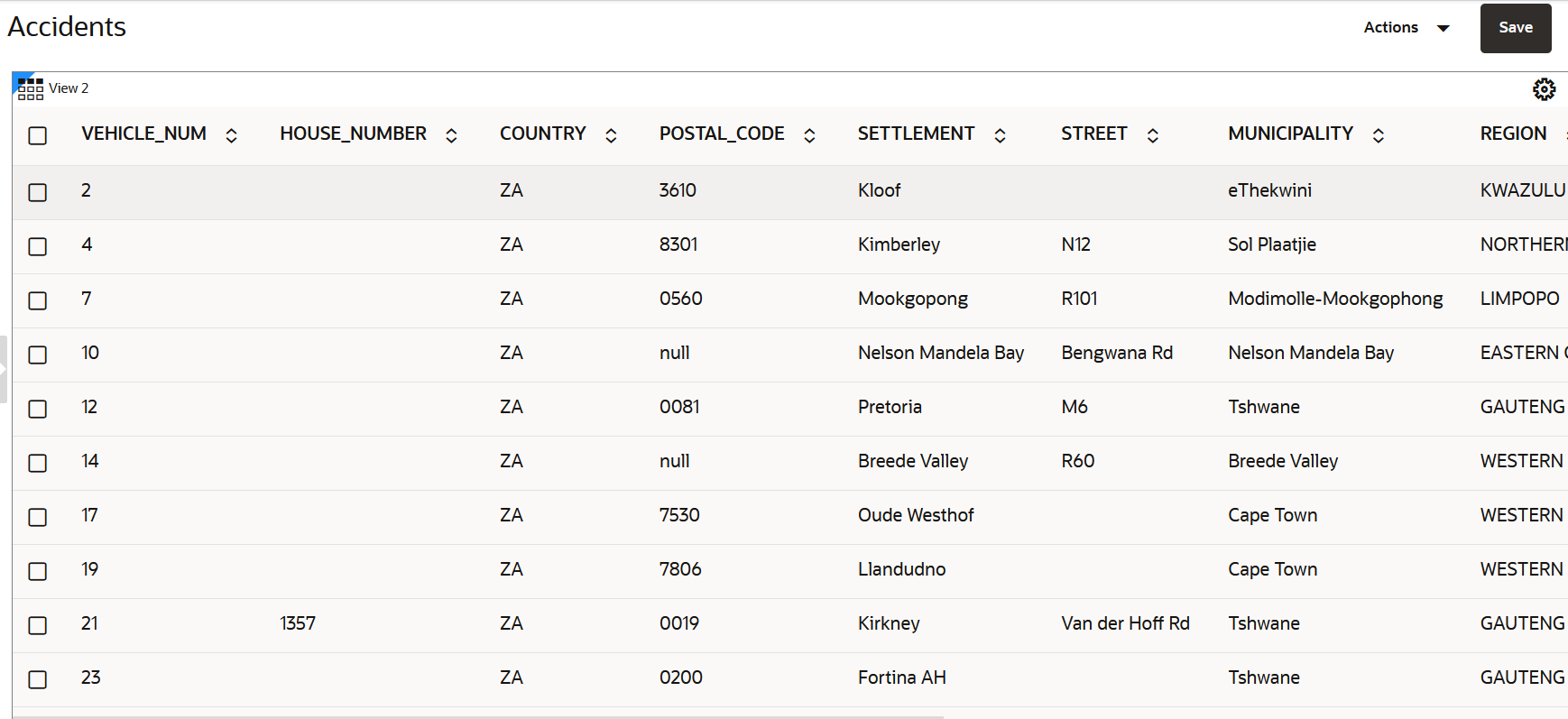
    This opens the data in tabular format for visualization as shown:

    Figure 3-25 Tabular Visualization

    Description of Figure 3-25 follows
    Description of "Figure 3-25 Tabular Visualization"

    You can easily scroll up or down the table to view the data rows as the table supports infinite scrolling.

    You can delete the table visualization by clicking the X icon on the top-right.

3.10.2 Using a Map Visualization

Spatial Studio supports the following types of map visualizations:

  • Geometry Data Visualization:
    • Point type
    • Line type
    • Polygon / Area type
  • GeoRaster Data Visualization
  • Hexagonal Data Visualization using H3 Aggregations

The following sections describe how to get started on these visualizations:

3.10.2.1 Visualizing a Point Map
Spatial Studio allows you to visualize the location of geographic data as points on maps.
To display your geographic data as maps, you must perform the following steps.
The instructions assume that the dataset for visualization is already added to the project in the Active Project page.
  1. Click the Visualizations tab on the left pane in the Active Project page.
    This lists the various visualization options.
  2. Click and drag Map from the list to the visualization window on the right to create a map visualization.
    A default base map is displayed with no data visualization layers.
  3. Click the Data tab on the left pane in the Active Project page.
    This lists all the Datasets that are loaded for the project.
  4. Click and drag the desired dataset from the list to the map view on the right.

    Tip:

    You can drag and drop multiple datasets in a single action to your map view.
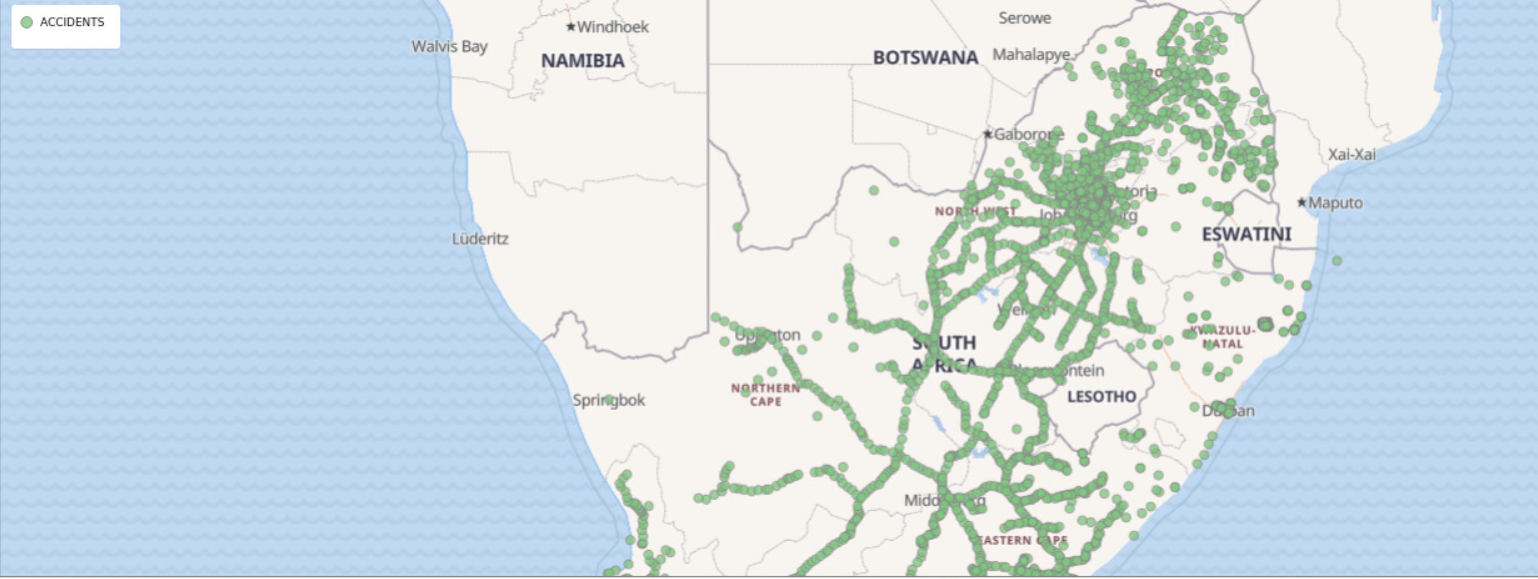
    The map gets updated with the data points for visualization as shown:

    You can render your map using different rendering styles. See Applying a Render Style For a Point Layer for more information.

    You can delete the map visualization by clicking the X icon on the top right.

3.10.2.2 About GeoRaster Data Visualization

Oracle Spatial Studio allows you to visualize GeoRaster data stored in spatial GeoRaster type in Oracle Database.

Geo-referenced raster data, including satellite imagery, aerial photos from drones, and gridded data, is very useful for mapping applications. It can be directly analyzed, or layered with vector data as a background map for additional context. See Spatial GeoRaster Developer's Guide for more information on GeoRaster data.

The following sections describe how you can create and visualize GeoRaster data in Spatial Studio.

3.10.2.2.1 Creating a GeoRaster Dataset
You can create a GeoRaster dataset using the following steps.
The instructions assume that the GeoRaster data is already existing in your database schema.
  1. Navigate to the Datasets page and click Create Dataset.
  2. Click From table/view, select a Connection and click Create.
  3. Click GeoRasters, select the required GeoRaster table and click OK as shown:

    Figure 3-27 Creating a GeoRaster DataSet

    Description of Figure 3-27 follows
    Description of "Figure 3-27 Creating a GeoRaster DataSet "
    The Geo-raster Configuration dialog opens.
  4. Choose a Selection Mode.
    The values for the selection mode are:
    • Single Raster
    • Virtual Mosaic
  5. Select the GeoRaster column for visualization if you have chosen the Single Raster mode. Otherwise, you can skip this step.

    Note:

    If you have chosen the Virtual Mosaic mode, all the Georaster columns are included in the visualization.
  6. Click OK.
    The GeoRaster dataset is configured and the newly created GeoRaster dataset is displayed as a row in the Datasets page.
3.10.2.2.2 Visualizing GeoRaster Data on a Map
You can visualize georaster data on a map using the following steps.
The instructions assume that the GeoRaster dataset is already added to the project in the Active Project page. To create a GeoRaster dataset, see Creating a GeoRaster Dataset for more information.
  1. Click the Visualizations tab on the left pane in the Active Project page.
    This lists the various visualization options.
  2. Click and drag Map from the list to the visualization window on the right to create a map visualization.
    A default base map is displayed with no data visualization layers.
  3. Click the Data tab on the left pane in the Active Project page.
    This lists all the Datasets that are loaded for the project.
  4. Click and drag the desired GeoRaster dataset from the list to the map view on the right.
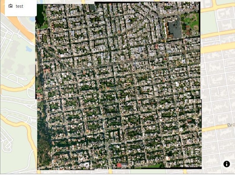
    A GeoRaster layer is created on the map as shown:

    Figure 3-28 GeoRaster Data Visualization

    Description of Figure 3-28 follows
    Description of "Figure 3-28 GeoRaster Data Visualization"

    You can delete the map visualization by clicking the X icon on the top right.

    Tip:

    You can enhance your visual display by modifying your Layer Settings using the Style tab and Raster tab. See Applying Style for a GeoRaster Layer for more information.
3.10.2.3 About Hexagonal Data Visualization Using H3 Aggregations

Oracle Spatial Studio allows you to visualize point-type map data using hexagons with H3 (Hexagonal Hierarchical Spatial Index) aggregations.

Visualizing your map data as hexagons has several advantages:
  • It helps you to identify patterns or clusters in a larger point dataset
  • Easier interpretation of data, as in a hexagonal cell, all the points are equidistant from the hexagon center-point
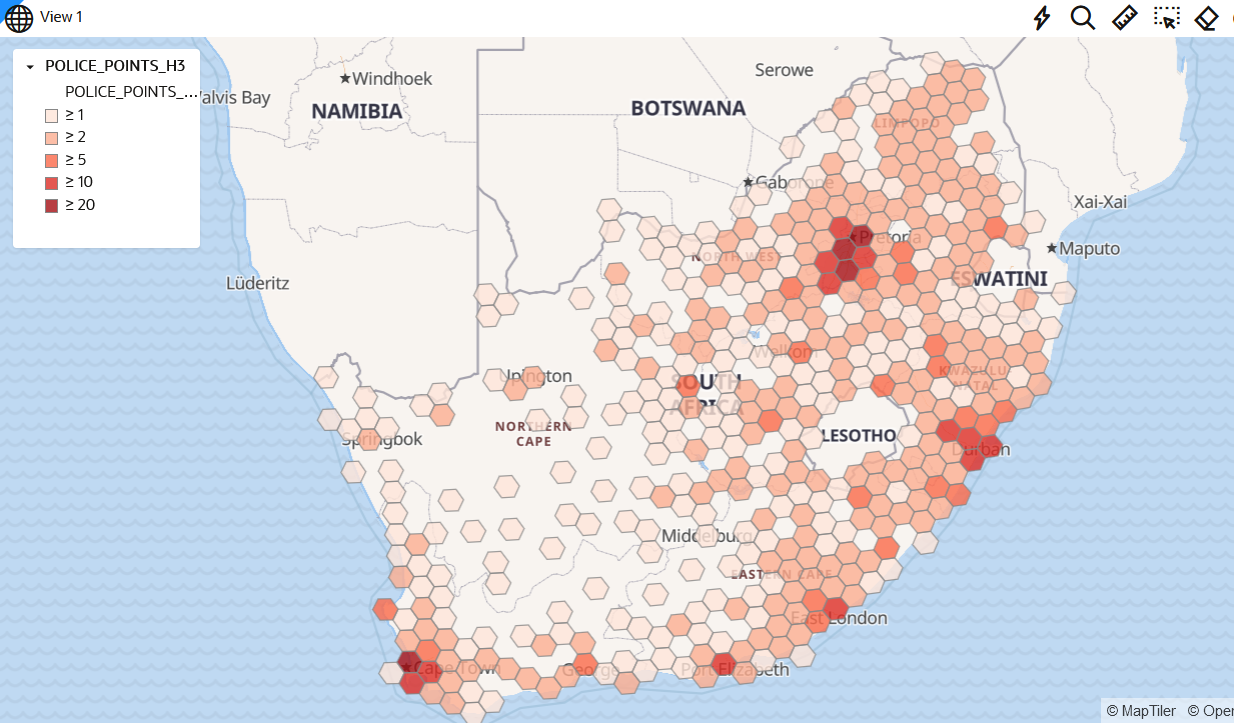
  • Hexagonal cells are color coded based on the number of datapoints they hold, which enables you to easily understand data patterns

The following sections describe how you can use H3 aggregations in Spatial Studio:

3.10.2.3.1 Preparing an H3 Aggregation Dataset
You can prepare an H3 aggregation dataset by performing the following steps.
The instructions assume that a dataset containing geometric data columns is already loaded to Spatial Studio.
  1. Navigate to the Datasets page.
    All the datasets loaded to Spatial Studio are shown listed on this page.
  2. Select the required dataset name and right-click to open the context menu.
  3. Click Create H3 Index on the Prepare submenu.
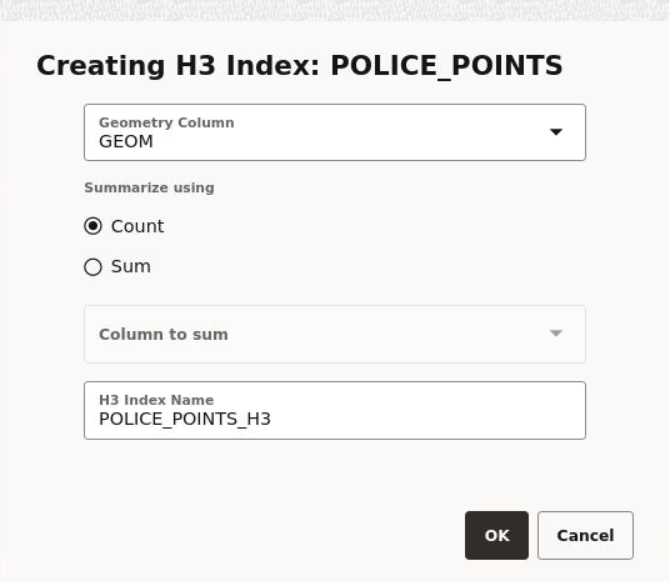
    The Creating H3 Index dialog opens as shown:

    Figure 3-29 Creating an H3 Aggregation Dataset

    Description of Figure 3-29 follows
    Description of "Figure 3-29 Creating an H3 Aggregation Dataset"
  4. Select the Geometry Column for H3 aggregations.
  5. Click a Summarize using option.
    The values for summarizing are:
    • Count: buckets the number of datapoints in each hexagon
    • Sum: adds up the values for a specific column in the data set, for all the points that fall in a specific hexagon
  6. Select the Column to sum, if you have chosen Sum to summarize your dataset. Otherwise, you can skip this step.
  7. Optionally, modify the H3 Index Name.
  8. Click OK.
    An H3 aggregation dataset is created and added as a new row in the Datasets page.
3.10.2.3.2 Visualizing Data With H3 Aggregations
To visualize your map data with H3 aggregations, you must perform the following steps.
The instructions assume that an H3 aggregation dataset is already added to the project in the Active Project page.

To prepare a dataset for H3 aggregation, see Preparing an H3 Aggregation Dataset for more information.

  1. Click the Visualizations tab on the left pane in the Active Project page.
    This lists the various visualization options.
  2. Click and drag Map from the list to the visualization window on the right to create a map visualization.
    A default base map is displayed with no data visualization layers.
  3. Click the Data tab on the left pane in the Active Project page.
    This lists all the Datasets that are loaded for the project.
  4. Click and drag the desired H3 Aggregation dataset from the list to the map view on the right.
    A layer showing the hexagonal binning of the data points is displayed on the map as shown:

    Figure 3-30 Map Data Visualization Using Hexagonal Binning

    Description of Figure 3-30 follows
    Description of "Figure 3-30 Map Data Visualization Using Hexagonal Binning"

    See Applying Data-Driven Style to a Map with H3 Aggregations for more information on applying styling for a H3 map layer.

3.10.2.4 About Custom Map Regions Visualization

Oracle Spatial Studio allows you to create custom map regions on map layers that support polygon type geometry.

You can create a new map region by selecting multiple polygon shapes and combining them with a new key-value. You can then append or insert this new map region with the new key-value into a target dataset containing all of your other custom map regions.

These newly created custom shapes are persisted on the underlying database table of the target dataset, and therefore can be used for data visualization or reporting just like any other dataset.

The following are the main characteristics for this feature support:
  • The source dataset, that is the dataset whose polygon shapes you will be selecting and then combining into a custom map region, must always be based on an Oracle Database table.

    Datasets from Oracle views and Studio's Analyses are not currently supported.

  • The new regions may or may not be contiguous.
  • The target dataset, that is the dataset on which you want to store the newly created custom map regions, will store them in its geo-reference system.
  • Only the key value and new geometry value are inserted into the target table.
  • The target dataset must meet the following requirements:
    • The geometry metadata information for the target dataset must be available in the SDO_GEOM_METADATA view.
    • A spatial index must exist on the geometry column.

      Note:

      If a spatial index is not created on the geometry column, then the target data layer cannot be dragged on to the map visualization canvas. See Creating a Target Dataset for more information.
3.10.2.4.1 Creating Custom Regions for Visualization
You can create custom polygon regions on the source dataset that contains polygon type geometries and apply them on a target dataset using the follow steps:
The instructions assume that the source and target datasets are already added to your Project in the ActiveProject page.
  1. Click the Visualizations tab on the left pane in the Active Project page.
    This lists the various visualization options.
  2. Click and drag Map from the list to the visualization window on the right to create a map visualization.
    A default base map is displayed with no data visualization layers.
  3. Click the Data tab on the left pane in the Active Project page.
    This lists all the Datasets that are loaded for the project.
  4. Click and drag the desired source dataset from the list to the map view on the right.
    A map layer with polygon shapes is created.
  5. Create the required custom regions by performing the following steps as many times as required:
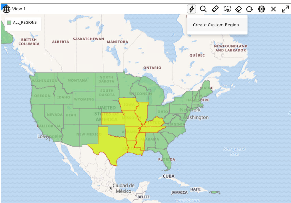
    1. Select the regions for aggregation using the polygon selection tool in the map tool bar.

      Figure 3-31 Creating Custom Map Shapes

      Description of Figure 3-31 follows
      Description of "Figure 3-31 Creating Custom Map Shapes"

      Tip:

      Alternatively, you can also select multiple polygons by using the keyboard shortcut Ctrl + Click on a Windows system.
    2. Click custom_region_icon , Merge Polygons Menu icon on the map tool bar and click Create Custom Region.
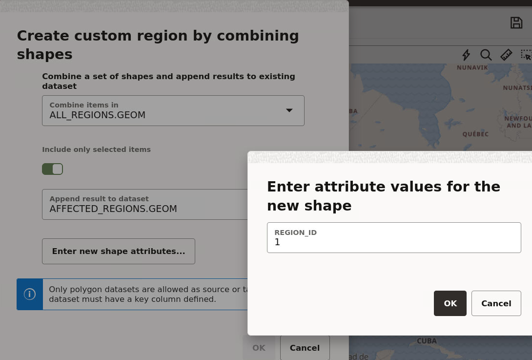
      Create custom region by combining shapes opens as shown:

      Figure 3-32 Create a Custom Region

      Description of Figure 3-32 follows
      Description of "Figure 3-32 Create a Custom Region"
    3. Select the source and target dataset and optionally switch on or off the Include only selected items toggle button:
      • Combine items in: source dataset
      • Append result to dataset: target dataset

      Caution:

      The whole source dataset may be aggregated into one region if Include only selected items is switched off. In this case the process may run for a long time depending on the number of features in the source dataset. Therefore, use this option only if required.
    4. Click Enter new shape attributes and enter a unique number for REGION_ID.
    5. Click OK to create the custom map region.
      Repeat steps a to d until you create the number of required custom regions.
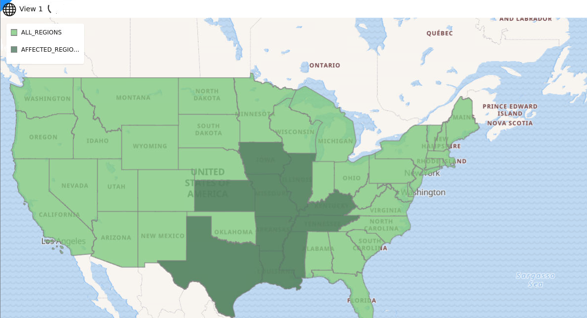
  6. Drag and drop the target dataset to the map view on the right to view the newly created custom regions.
    The following figure shows the newly defined custom region that was inserted into the target dataset.

    Figure 3-33 Displaying the Custom Shape on the Target Dataset

    Description of Figure 3-33 follows
    Description of "Figure 3-33 Displaying the Custom Shape on the Target Dataset"
3.10.2.4.2 Creating a Target Dataset
You can create a target dataset by performing the following steps:
  1. Connect to an Oracle database schema using SQL Developer or any other tools.
  2. Create a spatial table as shown:
    CREATE TABLE affected_regions (region_id NUMBER PRIMARY KEY, geom SDO_GEOMETRY);
  3. Insert the spatial table into USER_SDO_GEOM_METADATA view. For example:
    INSERT INTO USER_SDO_GEOM_METADATA VALUES (
    'affected_regions', -- TABLE_NAME
    'geom', -- COLUMN_NAME
    SDO_DIM_ARRAY -- DIMINFO attribute for storing dimension bounds, 0.5 m as tolerance
    (SDO_DIM_ELEMENT ('LONGITUDE', -180, 180, 0.5 ),
     SDO_DIM_ELEMENT ( 'LATITUDE', -90, 90, 0.5 )), 
    4326 -- SRID value for specifying a geodetic coordinate system
    );
    COMMIT;
  4. Create a spatial index on the SDO_GEOMETRY column.
    CREATE INDEX affected_regions_sidx ON affected_regions(geom) INDEXTYPE IS MDSYS.SPATIAL_INDEX_V2;
  5. Create a dataset in Spatial Studio from the database schema used in the preceding steps.
    The required target dataset is created. You may use this data layer on to which you can apply the newly created custom map regions.
3.10.2.5 Visualizing a Moving Object

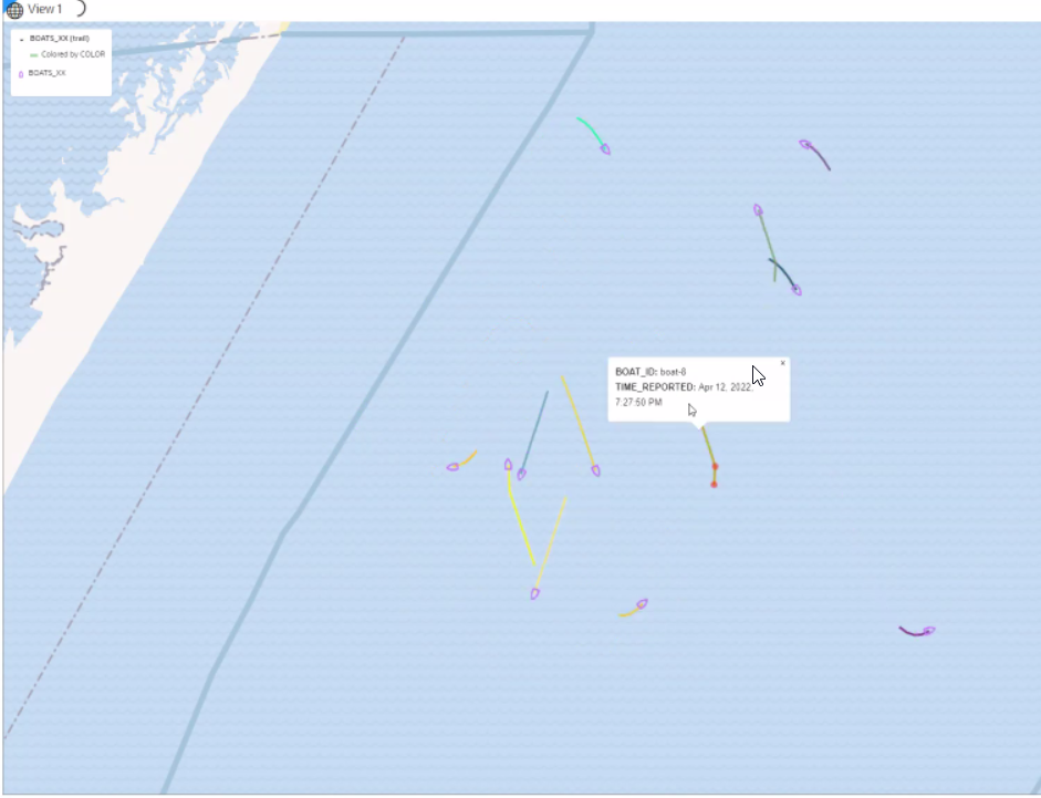
Starting from Oracle Spatial Studio Release 22.1.0, you can visualize moving objects using a spatiotemporal dataset.

Figure 3-34 Moving Objects Visualization

Description of Figure 3-34 follows
Description of "Figure 3-34 Moving Objects Visualization"

To get started on visualizing moving objects in Spatial Studio, you must:

  1. Enable a dataset as a spatiotemporal dataset by defining the essential space, time and entity information.
  2. Configure animation settings after adding the spatiotemporal dataset to a map for visualization.

The following sections describe in detail how you can perform the preceding two steps:

3.10.2.5.1 Enabling Spatiotemporal for a Dataset

In order to visualize and animate moving objects, you must enable Spatiotemporal for the dataset containing spatiotemporal data on the Datasets page.

Spatial Studio considers a dataset to contain spatiotemporal data only if it meets the following requirements:
  • It must be based on a geometry table or view with a geometry column or pair of latitude/longitude columns.
  • There must be one or more “moving objects” or entities uniquely identified by one of the columns.
  • There must be a column of the type TIMESTAMP, that stores the UTC datetime of the entities as they are being observed and recorded.
  • The dataset's underlying table or view must have ongoing inserts with recently obtained location data of entities being observed or monitored.

You can perform the following steps to enable spatiotemporal for a dataset. The instructions assume that the dataset containing spatiotemporal data is already existing in your database schema.

  1. Navigate to the Datasets page.
  2. Right-click on the spatiotemporal dataset and click Properties.
    The Dataset Properties dialog opens.
  3. Click the Spatiotemporal tab.
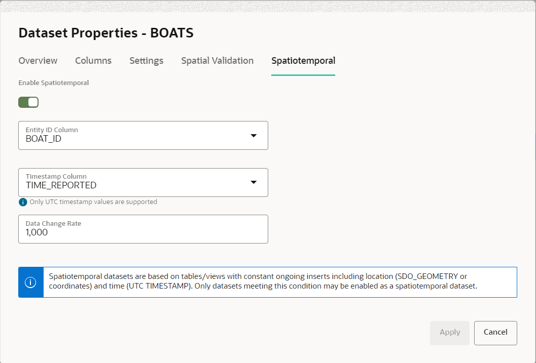
    The tab display opens as shown:

    Figure 3-35 Enabling Spatiotemporal for a Dataset

    Description of Figure 3-35 follows
    Description of "Figure 3-35 Enabling Spatiotemporal for a Dataset"
  4. Switch ON Enable Spatiotemporal.
  5. Select the Entity_ID Column that identifies a set of unique entities.
    The Entity_ID Column is not a unique column as each entity can have many recordings of its locations in the same table.
  6. Select the Timestamp Column.
    Spatial Studio supports only UTC (Coordinated Universal Time) or GMT (Greenwich Mean Time) time zone for visualizing moving objects.
  7. Specify Data Change Rate to indicate the approximate frequency of the live feed updates in the table.
  8. Click Apply.
Your dataset is now enabled for spatiotemporal data visualization.
3.10.2.5.2 Configuring Animation for a Moving Object

To visualize moving objects on a map in Spatial Studio, you must configure the animation settings on the map layer.

The following instructions assume that you have enabled spatiotemporal for the dataset and the dataset is already added to the project in the Active Project page. See Enabling Spatiotemporal for a Dataset for more information.
  1. Click the Visualizations tab on the left pane in the Active Project page.
    This lists the various visualization options.
  2. Click and drag Map from the list to the visualization window on the right to create a map visualization.
    A default base map is displayed with no data visualization layers.
  3. Click the Data tab on the left pane in the Active Project page.
    This lists all the Datasets that are loaded for the project.
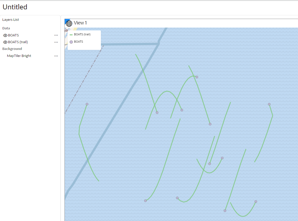
  4. Click and drag the desired spatiotemporal dataset from the list to the map view on the right. Two map layers are created on the map as shown:

    Figure 3-36 Map Visualization Using a Spatiotemporal Dataset

    Description of Figure 3-36 follows
    Description of "Figure 3-36 Map Visualization Using a Spatiotemporal Dataset"
    The second layer representing the trails of the moving object is added automatically in Spatial Studio. See Characteristics of Spatiotemporal Map Layers for more information on the two map layers.
  5. Perform the following steps to enable animation of the object along the trails:
    • Click Menu Icon against the initial layer in the Data tab of the Layers list.
    • Select Settings in the context menu and click Configure Animation.

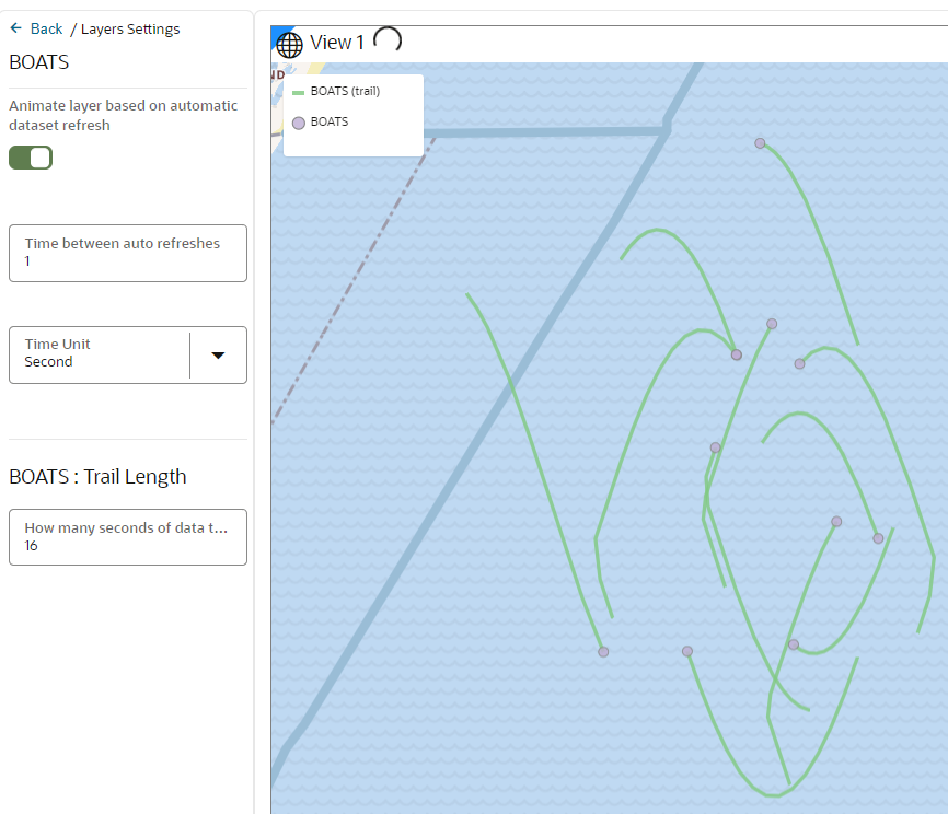
      The animation settings for the map layer opens as shown:

      Figure 3-37 Configuring Animation Settings

      Description of Figure 3-37 follows
      Description of "Figure 3-37 Configuring Animation Settings"
    • Switch ON Animate layer based on automatic dataset refresh.
    • Specify Time between auto refreshes to indicate the frequency of data refresh from the backend. This configuration also determines the smoothness and speed of the temporal animation.

      Note that Spatial Studio displays a default frequency value which is same as the Data Change Rate value configured on the Spatiotemporal dataset used for the visualization.

    • Specify a Time Unit.
    • Specify the Trail Length of your moving object. A trail length value of N indicates that Spatial Studio must fetch the recent N seconds of data of the moving object during every refresh.

      Tip:

      If the underlying database table or view contains millions of records, you can limit the map animation to display only the most recent N seconds of data as configured in Trail Length.

      Note that Spatial Studio displays a default trail length value which is 15 times the Data Change Rate value configured on the Spatiotemporal dataset and is rounded to the nearest integer.

    The animation settings are configured and you can view the animation of moving objects on the map.

    Note:

    You can choose a symbol and color for your moving object. However, ensure that the symbol you select adheres to the conditions explained in Characteristics of Spatiotemporal Map Layers.
3.10.2.5.3 Characteristics of Spatiotemporal Map Layers

This section describes the distinct characteristics of the spatiotemporal map layers when visualizing a spatiotemporal dataset.

  • The trails map layer is considered the secondary layer to the main layer. If you delete the main layer from the map, then the trails map layer is automatically deleted as well.
  • The main layer which shares the same name as the dataset is always a Point-type layer, that you can visualize using either as circle or using symbols or icons. When you use symbols, Spatial Studio will also automatically rotate the symbol based on the direction your object is moving.

    Also note, the current release of Spatial Studio supports only those symbols that naturally point North (or point up) or those that do not represent an inherent direction or angle, such as any rounded symbols.

  • The main layer will keep its animation even when you toggle the secondary layer invisible. However, if you toggle the main layer invisible, the trail layer will remain static as no new data is fetched from the backend.
  • You cannot switch the main layer to Heatmap or Cluster type.
  • You cannot use sticky Tooltip or popup as they cannot stick to the moving object when it moves to new locations.
  • Spatial Studio drives the animation of moving objects and their trails by constantly refreshing the main layer’s data from the backend. This implies that the base table is queried and the last N seconds of data is fetched by filtering the records based on the TIMESTAMP column.
  • If you are working in a multi-user or multi-visualization environment or both, you must take care to avoid overloading the database with many animating layer's data refresh queries. For instance, ensure a layer is not refreshing its data too frequently, or fetching too many seconds of data on each refresh, or both.

3.10.3 Using a Cesium Map Visualization

Spatial Studio uses a CesiumJS plugin to enable you to view 3D visualizations using 3D Tiles or CZML data on a Cesium map.

Cesium map allows you to display your real-world geospatial 3D data in a 3D environment. In order to build interactive 3D visualizations using Cesium maps, you can upload one of the following files to Spatial Studio:

  • 3D Tileset: Supports formats are:
    • Point Cloud (.pnts)
    • Batched 3D Model (.b3dm)
  • CZML file: CZML formatted data in .czml files

It is important to note the following when using a Cesium map visualization:

  • Generating 3D Tiles or CZML formatted data file for your geospatial 3D data must be carried out using any third party software outside of Oracle Spatial Studio.
  • 3D Tiles and CZML files are stored in the file system on Spatial Studio's server, not in Oracle Database.
  • Currently this feature supports only displaying 3D Tiles and CZML data on maps. It does not support 3D analysis.
3.10.3.1 Visualizing a 3D Tileset Using a Cesium Map
You can visualize your dataset with 3D Tiles on a Cesium map using the following steps.
The instructions assume that the 3D Tiles are uploaded and the dataset is already added to the project in the Active Project page. To create a dataset with 3D Tiles, see Creating a Dataset for more information.
  1. Click the Visualizations tab on the left pane in the Active Project page.
    This lists the various visualization options.
  2. Click and drag Cesium-Map from the list to the visualization canvas on the right to create a Cesium map visualization.
    A default Cesium map is displayed.

    Tip:

    You can configure new background Cesium maps by adding maps from the following two sources:
    • URL template
    • WMTS service
  3. Click the Data tab on the left pane in the Active Project page.
    This lists all the Datasets that are loaded for the project.
  4. Click and drag the desired 3D Tiles dataset from the list to the map view on the right.
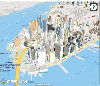
    A 3D layer is created on the map as shown:

    Figure 3-38 3D Cesium Map Visualization

    Description of Figure 3-38 follows
    Description of "Figure 3-38 3D Cesium Map Visualization"
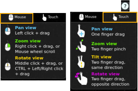
    To interact with the map, click the ? icon and use either of the following options shown: Description of pointer_options.png follows
    Description of the illustration pointer_options.png
3.10.3.2 Visualizing CZML Data Using a Cesium Map
You can visualize your CZML dataset on a Cesium map using the following steps.
The instructions assume that the CZML formatted data is uploaded and the CZML dataset is already added to the project in the Active Project page. To create a dataset using .czml file, see Creating a Dataset for more information.
  1. Click the Visualizations tab on the left pane in the Active Project page.
    This lists the various visualization options.
  2. Click and drag Cesium-Map from the list to the visualization canvas on the right to create a Cesium map visualization.
  3. Click the Data tab on the left pane in the Active Project page.
    This lists all the Datasets that are loaded for the project.
  4. Click and drag the desired CZML dataset from the list to the map view on the right.
    A 3D layer is created on the map as shown:

    Figure 3-39 Cesium Map Visualization Using a CZML Dataset

    Description of Figure 3-39 follows
    Description of "Figure 3-39 Cesium Map Visualization Using a CZML Dataset"

3.10.4 Styling a Map Layer

Spatial Studio allows you to explore different styling options for your map layers, in order to enhance visualization and analysis.

The styling options provided to you may vary depending on the type of data you are mapping.

The following sections describe a few styling techniques for the different data types:

3.10.4.1 Applying a Render Style For a Point Layer
You can render a point map layer using one of the following render style options:
  • Circle (default)
  • Symbol
  • Heatmap
  • Cluster

The following steps enable you to apply your preferred render style option.

The instructions assume that you have point map layer displayed on your Active Project page.
  1. Click Menu Icon against the map layer in the Layers tab of the Layers List.
  2. Select Settings in the context menu.
  3. Configure Style and select a Render Style option from the drop-down list.
    By default, a point map layer always uses Circle to represent the data points.

    Note:

    Each render style has its own settings.
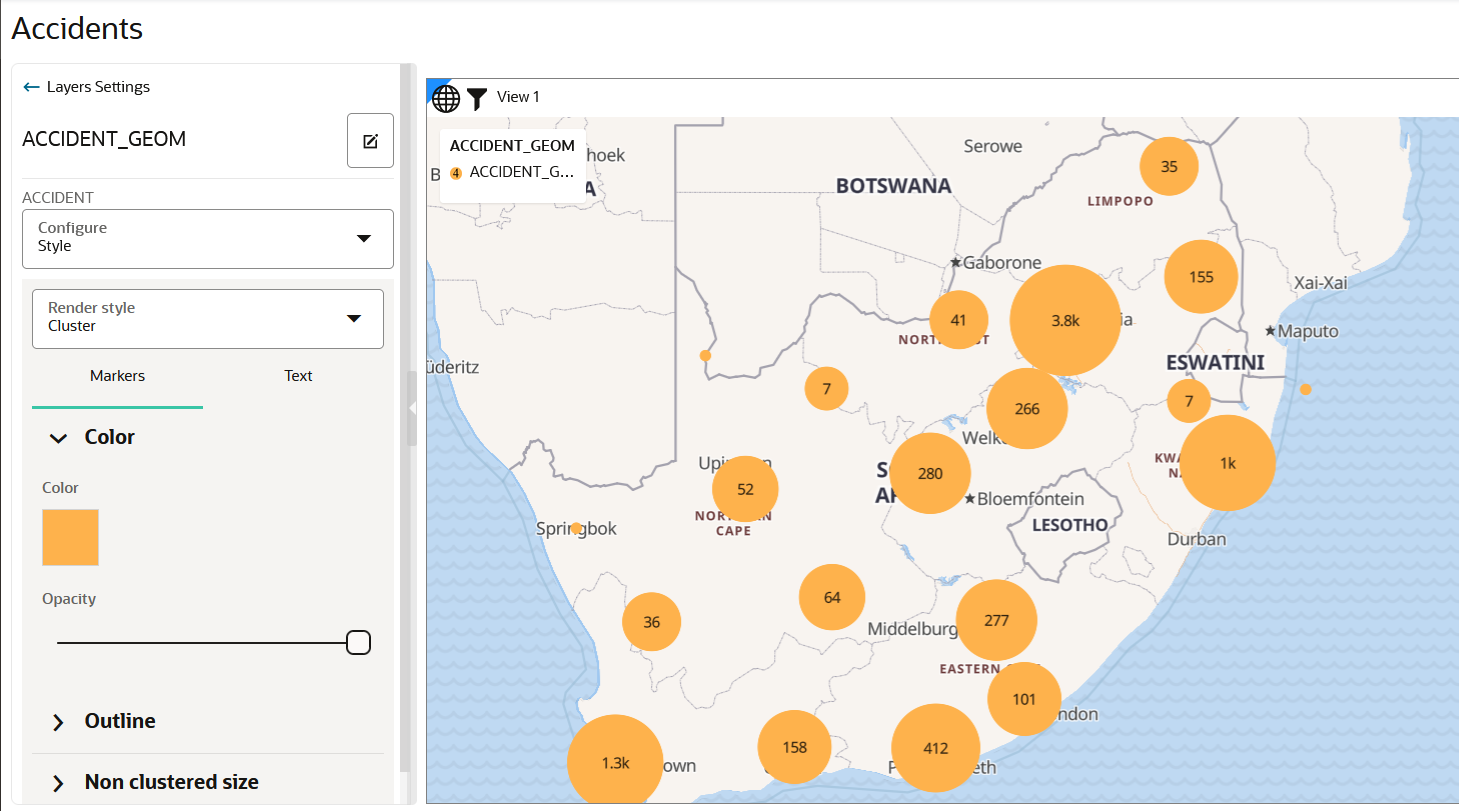
    • If you select Cluster as the render style option, the data points on your map are shown clustered depending on the cluster circle size.

      Figure 3-40 Applying a Cluster Style

      Description of Figure 3-40 follows
      Description of "Figure 3-40 Applying a Cluster Style"

      Optionally, you can change the color and the style of the text labels representing the number of points in each cluster.

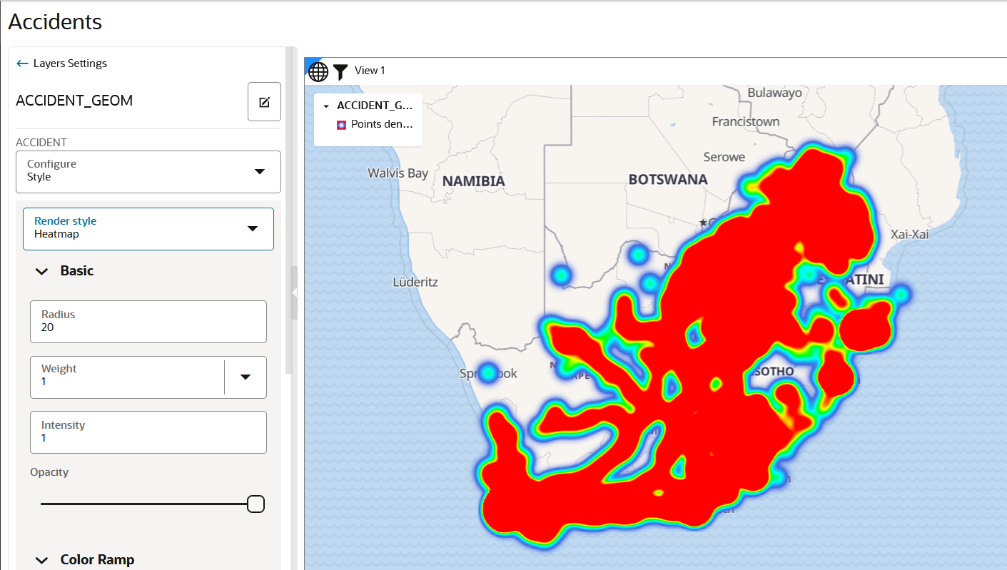
    • If you select HeatMap as the render style option, the data points on your map are rendered with continuous colors based on the concentration of points as shown:

      Note:

      Hot colors represent concentration of points, and cool colors represent sparsity of points.

      Tip:

      It is recommended that you reduce the default value of the Radius parameter to observe a more localized view of point concentrations.

      Figure 3-41 Applying a HeatMap Style

      Description of Figure 3-41 follows
      Description of "Figure 3-41 Applying a HeatMap Style"
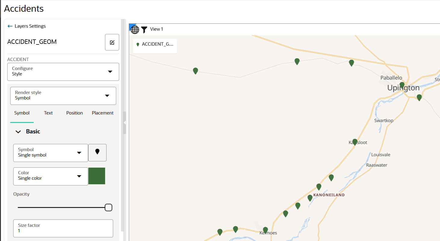
    • If you select Symbol as the render style option, the data points on your map are rendered with your chosen symbol as shown:

      Tip:

      You can optionally select a color for your symbol.

      Figure 3-42 Applying a Symbol Style

      Description of Figure 3-42 follows
      Description of "Figure 3-42 Applying a Symbol Style"
    The map layer gets rendered with the appropriate style.
3.10.4.2 Applying Style for a GeoRaster Layer
You can style a GeoRaster map layer using the following steps.
The instructions assume that you have a GeoRaster map layer displayed on your Active Project page.
  1. Click Menu Icon against the dataset in the Data tab of the Layers list.
  2. Select Settings in the context menu.
    The Layer Settings panel opens.
  3. Optionally, modify any of the following options in the Style:
    • Opacity
    • Maximum Brightness
    • Minimum Brightness
    • Saturation
    • Contrast
    • Hue Rotate
    • Fade Duration
  4. Optionally, modify any of the following rendering options in the Raster tab:
    • Bands: Spatial Studio, by default supports the following bands:
      • Red
      • Blue
      • Green
      • Alpha

      For GeoRaster images that have more than three layers, you can choose which three layers you want to visualize.

    • Reprojection: represents the interpolation method to be used when transforming an image from one SRS (Spatial Reference System) to another.
    • Image Processing: represents the subprogram to be used to enhance the visual quality of the images.
    • Rendering Hints: represents the image interpolation value that determines how each image cell's value on a view port is interpolated using the original image pixels. For example:
      • NEAREST NEIGHBOR: This option has no interpolation by taking the nearest image pixel's value directly.
      • BI-LINEAR: This option will consider 4 neighboring pixels to determine the image cell's value on a view port.

      Additionally, you can also switch on or off the Transparent NODATA toggle, which determines if the image cells are to be transparent or not. If the switch is on, then the layers underneath will be visible for areas that have NODATA in the image.

    The GeoRaster map layer is rendered with the updated settings.
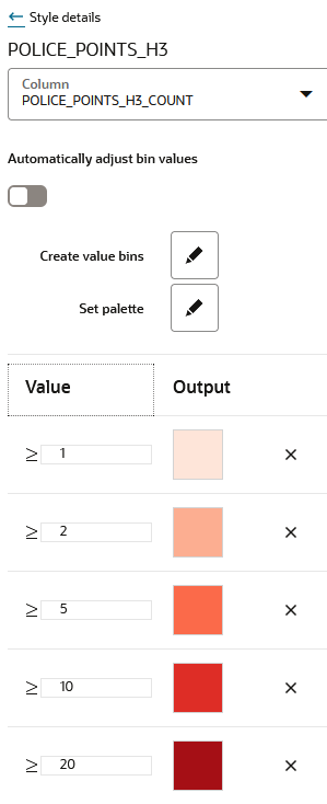
3.10.4.3 Applying Data-Driven Style to a Map with H3 Aggregations

You can apply different resolutions to your H3 map layer to enhance your visualization.

In case of an H3 aggregation dataset, the hexagonal cells and the distribution of points in these hexagons automatically change at each resolution level, as you zoom in and out of the map. This implies that the color bins for one level might not be the same as for another level.

Spatial Studio provides an option to automatically calculate color bins as you alter your resolutions. You can also turn this option off if you want to test against a set of specific thresholds.

The following steps enable you to apply a data-driven styling option for your H3 map layer.

The instructions assume that you have a H3 map layer displayed on your Active Project page.
  1. Click Menu Icon against the map layer in the Layers tab of the Layers List list.
  2. Select Settings in the context menu.
  3. Configure Style.
  4. Select Based on Data for the Color value under Fill.
    The Style details panel is displayed.
  5. Select the Column to control styling.
  6. Switch on or off the Automatically adjust bin values toggle button.
    • If turned on, the bin values will automatically update as you zoom in or out on the map.
    • If turned off, Create value bins option appears.
  7. Assign colors to the bins based on data values.
    The following figure shows the Style details panel options:

    Figure 3-43 Applying Data-Driven Color Styling for H3 Map Layer

    Description of Figure 3-43 follows
    Description of "Figure 3-43 Applying Data-Driven Color Styling for H3 Map Layer"
    The color bins on the H3 map layer gets rendered appropriately for different resolutions as shown in the preceding figure.
3.10.4.4 Applying Predefined Colors to a Map Layer

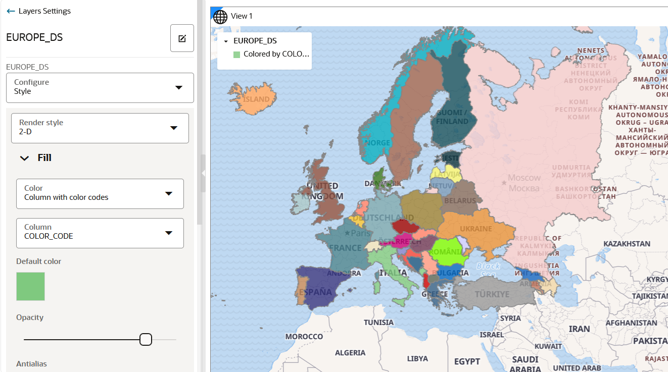
Using a column with predefined color codes or values, you can create accurate and consistent choropleth map layers.

You can store a color-coded value in a column of your dataset and then use this column property to color code your map.

The following steps enable you to color code your map layer.

The instructions assume that the map layer displayed on your Active Project page uses a dataset having a column property that contains color-coded values.
  1. Click Menu Icon against the map layer in the Layers tab of the Layers List.
  2. Select Settings in the context menu.
  3. Configure Style by selecting Column with color codes for the Color value under Fill.
  4. Select the Column that contains the color value.
    The following figure shows the styling of the map layer using the color variable in the dataset:

    Figure 3-44 Color Coding a Map Layer

    Description of Figure 3-44 follows
    Description of "Figure 3-44 Color Coding a Map Layer"

    The color code gets applied to the map layer.

3.10.4.5 Applying Predefined Symbols to a Map Layer

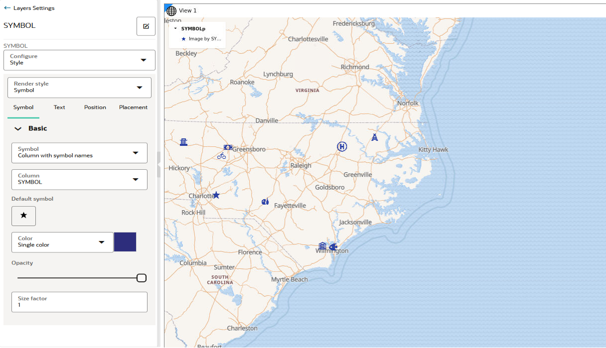
Using a column with predefined symbol values, you can apply data-driven symbol styling to your map layer.

However, the symbol must belong to one of the supported symbol sets. Symbols in Spatial Studio are grouped into three sets and each set is identified by a Symbol set id as described in the following table:

Table 3-2 Symbol Set

Symbol Set Symbol set id
Spatial Studio default studio
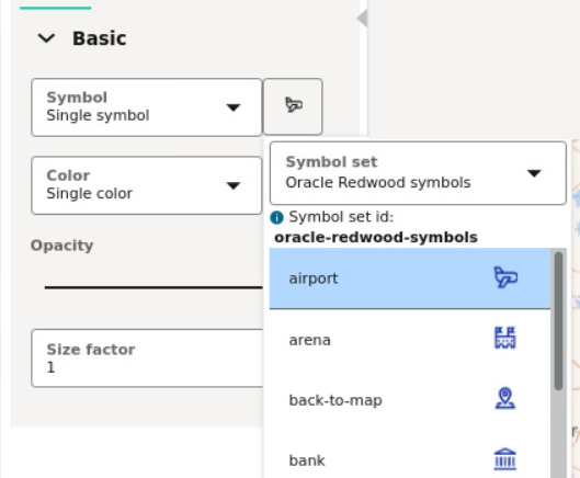
Oracle Redwood symbols oracle-redwood-symbols
Airfields airfields

You can store a symbol name and the symbol set to which it belongs in a column of your dataset and then use this column property to assign symbols to your map.

For example, assume you want to use the airport icon as shown in the following figure:

Figure 3-45 Symbols and Symbol Set

Description of Figure 3-45 follows
Description of "Figure 3-45 Symbols and Symbol Set"

You must then use oracle-redwood-symbols/airport as the symbol name in your dataset column. In this case:

  • oracle-redwood-symbols: is the symbol set id
  • airport: is the name for the icon to be used on the map layer

The following steps enable you to apply data driven symbol styling for your map layer.

The instructions assume that the map layer displayed on your Active Project page uses a dataset having a column property that contains symbol names following the convention as explained earlier in this section.
  1. Click Menu Icon against the map layer in the Layers tab of the Layers list.
  2. Select Settings in the context menu.
  3. Configure Style and select Symbol as the Render Style.
  4. Select Column with symbol names from the Symbol drop-down list in the Basic section of the Symbol tab.
  5. Select the Column that contains the symbol name value.
    The following figure shows the styling of the map layer using the symbol name variables in the dataset:

    Note:

    If incorrect symbol names are present in the dataset column, then for those data points, the Default symbol is displayed on the map layer.

    Figure 3-46 Custom Symbol Styling in Map Visualization

    Description of Figure 3-46 follows
    Description of "Figure 3-46 Custom Symbol Styling in Map Visualization"

    The symbols gets applied to the map layer.

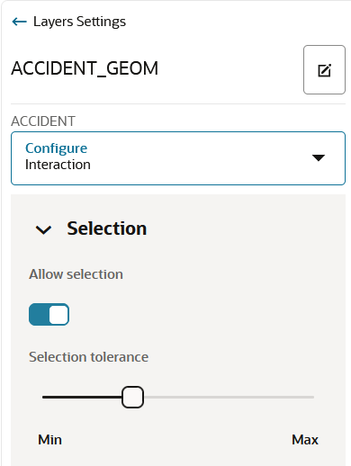
3.10.4.6 Setting Selection Tolerance on a Map Layer

Spatial Studio allows you to increase or decrease the selection tolerance on a map layer, so that selecting small and linear geometry features is easier.

The following steps enable you to adjust and set the selection tolerance on a map.

The instructions assume that a project is open on the Active Project page.
  1. Click Menu Icon against the dataset in the Data tab of the Layers list.
  2. Select Settings in the context menu and configure Interaction.
  3. Switch on the Allow selection toggle button.
  4. Adjust the Selection tolerance slider as required.
    The following figure shows the Selection section for setting the tolerance:

    Figure 3-47 Setting the Selection Tolerance

    Description of Figure 3-47 follows
    Description of "Figure 3-47 Setting the Selection Tolerance"

    The custom selection tolerance gets applied to the map layer.

3.10.4.7 Adding a Pin on a Map

The following steps enable you to inspect the current mouse pointer's latitude and longitude coordinates and pin a location on the map layer.

The instructions assume that you have a project opened on your Active Project page and the map layer is displayed for visualization.
  1. Right-click on any area on the map layer.
    The coordinates for the location gets displayed as shown:

    Figure 3-48 Pin a Location on the Map

    Description of Figure 3-48 follows
    Description of "Figure 3-48 Pin a Location on the Map"
  2. Click Drop a pin to add a location marker.
    The pin gets displayed on the map. Additionally, you can also copy the coordinates by clicking on the marker and then clicking the Longitude, Latitude: click to copy icon.
3.10.4.8 Applying Map Backgrounds

Spatial Studio provides ready-to-use map backgrounds to enhance your visualization.

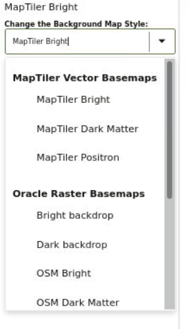
You can select one of the following map backgrounds for your project visualization:

  • MapTiler Vector Basemaps
  • Oracle Raster Basemaps
  • Blank Basemaps
  • User-defined Basemaps

As an administrator, you can also register custom basemaps and use them in map visualizations. They may be raster or vector tiles that are typically hosted on third party servers, or they be created using a WMS OGC web service. See Spatial Studio Administration Page for more information on adding basemaps.

The following section describes how to apply a specific map background for your project:

3.10.4.8.1 Changing Map Backgrounds

The following steps enable you to apply different map backgrounds in your project visualization.

The instructions assume that you have a project opened on your Active Project page.
  1. Click Menu Icon in the Background tab of the Layers list.
  2. Select Settings in the context menu.
  3. Click the Change the Background Map Style drop-down and select your required background map as shown.

    Figure 3-49 Changing a Map Background

    Description of Figure 3-49 follows
    Description of "Figure 3-49 Changing a Map Background"

    All custom basemaps appear under User-defined Basemaps in the drop-down list.

    The selected map background gets applied to your project visualization.

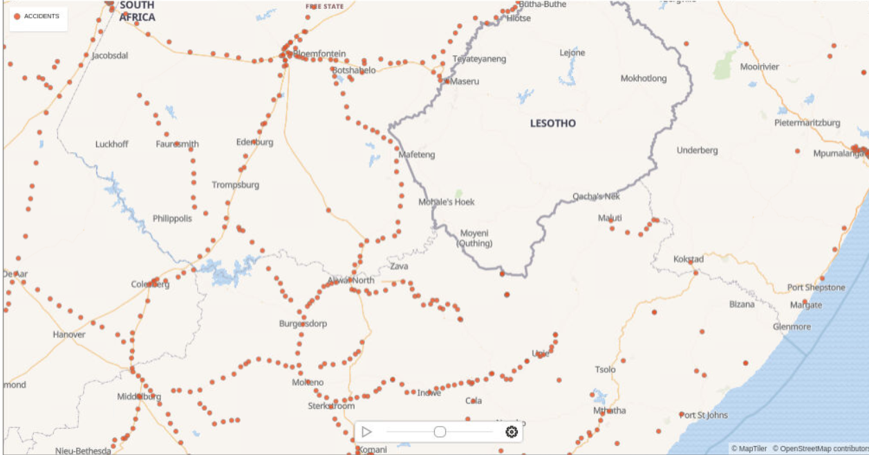
3.10.5 Visualizing Map Data Over Time

Spatial Studio allows you to perform dynamic map visualizations.

In order to visualize map data over time, your dataset must contain a date column or a time column or both. You can then use the time slider feature to interact with the map.

Note:

The time slider is applicable only for datasets containing event points or simple shapes over time, such as earthquakes or storm paths. It does not apply for datasets containing a fixed set of shapes with attributes varying over time, such as countries with population.

The following steps allow you to configure and use a time slider for your map visualization.

The instructions assume that you have a project linked to a dataset containing date or time data and the project is opened on your Active Project page.
  1. Click the Settings icon in your map tool bar.
  2. Switch on the Show time slider toggle button and click OK.
    A time slider bar appears at the bottom of the map visualization canvas.
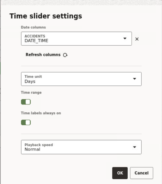
  3. Click the Time slider settings icon on the time slider bar.

    Figure 3-50 Time slider Settings

    Description of Figure 3-50 follows
    Description of "Figure 3-50 Time slider Settings"
  4. Select the Date columns and the Time unit to be applied for visualization.
  5. Optionally, switch on or off the Time range and Time labels always on toggle buttons.
  6. Optionally, select Playback speed.
  7. Click OK.
    You can now interact with your map using the time slider to view the change of your data over time.

    Figure 3-51 Using a Time slider in Map Visualization

    Description of Figure 3-51 follows
    Description of "Figure 3-51 Using a Time slider in Map Visualization"

3.11 Performing Analyses in Spatial Studio
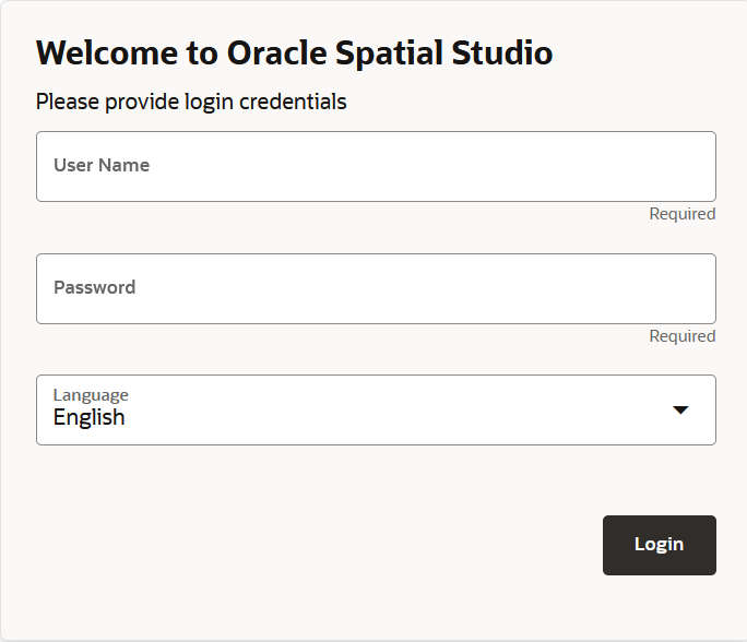
You can perform various spatial analyses (such as filtering by proximity, nearest neighbor analysis and so on) and visualize the results in Spatial Studio.

These spatial analyses are grouped under the following categories in Spatial Studio :
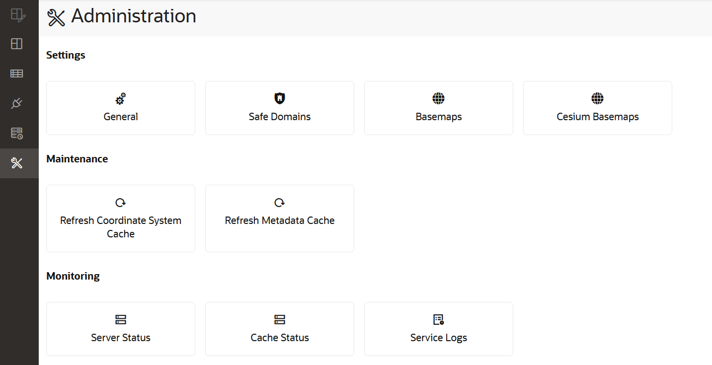
  • Filter
  • Combine
  • Transform
  • Measure
  • Analytics

Figure 3-52 Spatial Analysis Operations

Description of Figure 3-52 follows
Description of "Figure 3-52 Spatial Analysis Operations"

The following topics explore spatial analysis using selected filter operations:

3.11.1 Determining the Geometries Within a Specified Distance

Using the SDO_WITHIN_DISTANCE filter, you can filter coordinates that are within a specific distance from a point on the map layer.
To filter points based on this proximity filter, you must perform the following steps.
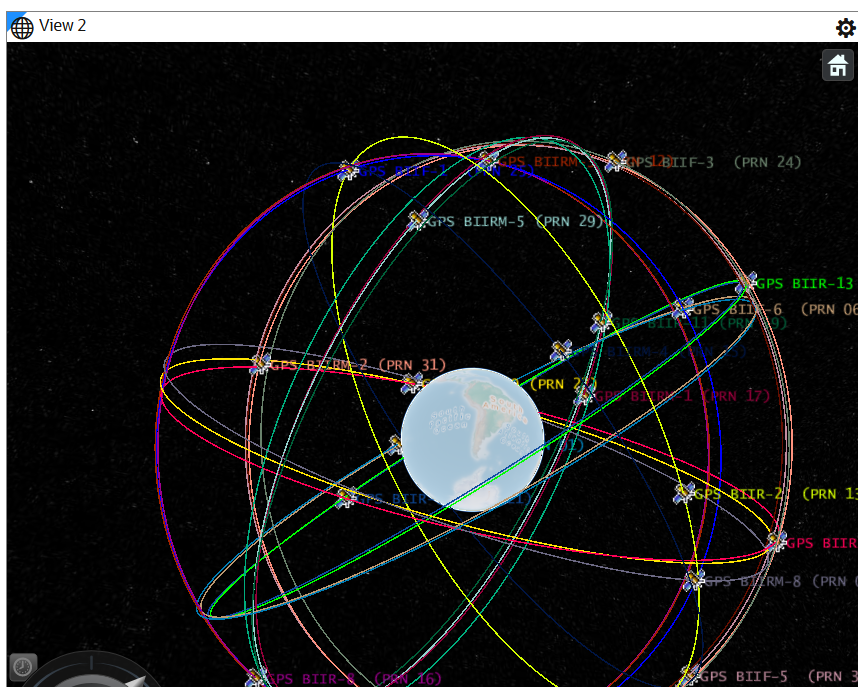
The instructions assume that you have the layer to be filtered and the map layer to be used as a filter displayed on your Active Project page.
  1. Click Menu Icon against the map layer whose coordinates needs to be filtered in the Layers tab.
  2. Select Spatial Analysis.
    The Spatial Analysis Operations window opens as shown in Figure 3-52.
  3. Click on the Filter tab and select Return shapes within a specific distance of another.
    Within distance dialog box opens as shown:

    Figure 3-53 Spatial Analysis - Within Distance Configuration

    Description of Figure 3-53 follows
    Description of "Figure 3-53 Spatial Analysis - Within Distance Configuration "
  4. Enter Analysis name.
  5. Select the Layer to be filtered.
  6. Select the Layer to be used as the filter.
  7. Enter distance and unit.
  8. Click Run.
    The Analysis result is listed under Analyses in the Data elements panel on the left pane of the Active Project page.
  9. Drag and drop the analysis result on the map view.
    This creates a new map layer highlighting the filtered coordinates within a specific distance from a point as shown:

    Figure 3-54 Spatial Analysis - Within Distance Visualization

    Description of Figure 3-54 follows
    Description of "Figure 3-54 Spatial Analysis - Within Distance Visualization"

3.11.2 Determining the N-Nearest Geometries

Using the SDO_NN_V2 filter, you can determine the N-nearest geometries to a geometry.

Note:

The SDO_NN_V2 filter is an improved form of the SDO_NN filter which was used in the earlier releases of Oracle Spatial Studio. The old behavior will continue to be supported when you modify analyses that were created using the SDO_NN filter. However, when creating a new analysis, the current SDO_NN_V2 filter will be used.
To find the N-nearest geometries, you must perform the following steps.
The instructions assume that you have the layer to be filtered and the map layer to be used as a filter displayed on your Active Project page.
  1. Click Menu Icon against the map layer, whose coordinates needs to be filtered, in the Layers tab.
  2. Select Spatial Analysis.
    The Spatial Analysis Operations window opens as shown in Figure 3-52.
  3. Click on the Filter tab and select Return shapes nearest to another.
    Nearest neighbors dialog box opens as shown:

    Figure 3-55 Nearest Neighbors Analysis

    Description of Figure 3-55 follows
    Description of "Figure 3-55 Nearest Neighbors Analysis"
  4. Enter Analysis name.
  5. Select the Layer to be filtered.

    Note:

    Ensure that you have run spatial validations on the map layer to be filtered and the map layer to be used as the filter in order to obtain accurate analysis results.
  6. Enter Number of results.
  7. Click Run.
    The Analysis result is listed under Analyses in the Data elements panel on the left pane of the Active Project page.
  8. Drag and drop the analysis result on the map view.
    This creates a new map layer highlighting the N-nearest neighbor geometries for a geometry.

3.11.3 Editing a Spatial Analysis

You can edit an existing spatial analysis to modify certain essential parameters.

However, only the following list of spatial analysis operations allow their parameters to be modified after creation:

Filter

  • SDO_FILTER
  • SDO_NN_V2
  • SDO_RELATE
  • SDO_WITHIN_DISTANCE

Combine

  • Spatial Join

Transform

  • SDO_BUFFER
  • SDO_MBC
  • SDO_UTIL.AT_BEARING
  • SDO_UTIL.SIMPLIFY
  • SDO_SAM.SIMPLIFY_GEOMETRY

Measure

  • SDO_GEOM.SDO_AREA
  • SDO_GEOM.SDO_DIAMETER
  • SDO_GEOM.SDO_LENGTH
  • SDO_GEOM.WITHIN_DISTANCE
  • SDO_GEOM.SDO_MAXDISTANCE
  • SDO_GEOM.SDO_MAX_MBR_ORDINATE
  • SDO_GEOM.SDO_MBC_RADIUS
  • SDO_GEOM.SDO_MIN_MBR_ORDINATE

Analytics

  • Summarize within distance
  • Summarize by region

To modify the parameters in a spatial analysis, you must perform the following steps.

The instructions assume that the analysis to be edited is present in the Active Project page.
  1. Click Menu Icon against the analysis to be edited under Analyses tab in the Data elements pane of the Active Project page.
  2. Select Modify Parameters as shown:

    Note:

    Modify Parameters in the context menu will be disabled for spatial analysis operations that cannot be modified.

    Figure 3-56 Modify Spatial Analysis Parameters

    Description of Figure 3-56 follows
    Description of "Figure 3-56 Modify Spatial Analysis Parameters"

    The dialog box displaying the original definition for the specific spatial analysis opens.

  3. Modify the required parameters and click Run.
    The analysis gets updated and the updates can be visualized in the map view.