2.2.4 Cabling Database Servers
After the new database servers are installed, they need to be cabled to the existing equipment. The following procedure describes how to cable the new equipment in the rack. The images shown in the procedure are of a Sun Fire X4170 M2 Oracle Database Server.
Note:
-
The existing cable connections in the rack do not change.
-
The blue cables connect to Oracle Database servers, and the black cables connect to Exadata Storage Servers. These network cables are for the NET0 Ethernet interface port.
-
Attach and route the management cables on the CMA and rear panel one server at a time. Do not slide out more than one server at a time.
-
Start from the bottom of the rack, and work upward. Route the cables through the CMA with the dongle on the top and power cables on the bottom.
-
Longer hook and loop straps are needed when cabling three CAT5e cables or two TwinAx cables.
-
Connect the CAT5e cables, AC power cables, and USB to their respective ports on the rear of the server. Ensure the flat side of the dongle is flush against the CMA inner rail.
Figure 2-3 Cables at the Rear of the Server
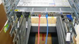
Description of "Figure 2-3 Cables at the Rear of the Server" -
Adjust the green cable management arm (CMA) brackets
Figure 2-4 Cable Management Arm (CMA) Brackets
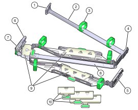
Description of "Figure 2-4 Cable Management Arm (CMA) Brackets"Description of the CMA callouts in the preceding image"
-
Connector A
-
Front slide bar
-
Velcro straps (6)
-
Connector B
-
Connector C
-
Connector D
-
Slide-rail latching bracket (used with connector D)
-
Rear slide bar
-
Cable covers
-
Cable covers
-
-
Attach the CMA to the server.
-
Route the CAT5e and power cables through the wire clip.
Figure 2-5 Cables Routed Through the Cable Management Arm
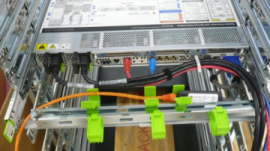
Description of "Figure 2-5 Cables Routed Through the Cable Management Arm" -
Bend the CAT5e and power cables to enter the CMA, while adhering to the bend radius minimums.
-
Secure the CAT5e and power cables under the cable clasps.
Figure 2-6 Cables Secured under the Cable Clasps
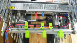
Description of "Figure 2-6 Cables Secured under the Cable Clasps" -
Route the cables through the CMA, and secure them with hook and loop straps at equal intervals.
Figure 2-7 Cables Secured with Hook and Loop Straps at Regular Intervals
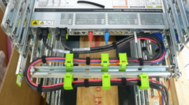
Description of "Figure 2-7 Cables Secured with Hook and Loop Straps at Regular Intervals" -
Connect the RDMA Network Fabric or TwinAx cables with the initial bend resting on the CMA. The TwinAx cables are for client access to the database servers.
Figure 2-8 RDMA Network Fabric or TwinAx Cables Positioned on the CMA
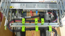
Description of "Figure 2-8 RDMA Network Fabric or TwinAx Cables Positioned on the CMA" -
Secure the RDMA Network Fabric or TwinAx cables with hook and loop straps at equal intervals.
Figure 2-9 RDMA Network Fabric or TwinAx Cables Secured with Hook and Loop Straps at Regular Intervals
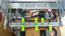
Description of "Figure 2-9 RDMA Network Fabric or TwinAx Cables Secured with Hook and Loop Straps at Regular Intervals" -
Route the fiber core cables.
-
Rest the cables over the green clasp on the CMA.
-
Attach the red ILOM cables to the database server.
-
Attach the network cables to the Oracle Database server.
-
Attach the cables from Oracle Database server to the RDMA Network Fabric switches.
-
Connect the orange Ethernet cable to the KVM switch.
-
Connect the red and blue Ethernet cables to the Cisco switch.
-
Verify operation of the slide rails and CMA for each server, as follows:
Note:
Oracle recommends that two people do this step. One person to move the server in and out of the rack, and another person to observe the cables and CMA.
-
Slowly pull the server out of the rack until the slide rails reach their stops.
-
Inspect the attached cables for any binding or kinks.
-
Verify the CMA extends fully from the slide rails.
-
-
Push the server back into the rack, as follows:
-
Release the two sets of slide rail stops.
-
Push in both levers simultaneously, and slide the server into the rack. The first stop in the set are levers located on the inside of each slide rail, just behind the back panel of the server. The levers are labeled
PUSH. The server slides approximately 46 cm (18 inches) and stop. -
Verify the cables and CMA retract without binding.
-
Simultaneously push or pull both slide rail release buttons, and push the server completely into the rack until both slide rails engage. The second stop in the set are the slide rail release buttons located near the front of each mounting bracket.
-
-
Dress the cables, and then tie off the cables with the straps. Oracle recommends the cables should be dressed in bundles of eight or less.
-
Extend and then fully retract the server to check cable travel by sliding each server out and back fully to ensure that the cables are not binding or catching.
-
Repeat the procedure for the rest of the servers.
-
Connect the power cables to the power distribution units (PDUs). Ensure the breaker switches are in the OFF position before connecting the power cables. Do not plug the power cables into the facility receptacles at this time.
See Also:
-
Oracle Exadata Database Machine System Overview for cabling tables
-
"Reviewing the Cable Management Arm Guidelines" for the bend radius minimums
Parent topic: Extending Elastic Configurations