Creating and Managing Flex Networks
Oracle Private Cloud Appliance supports direct connectivity to external racks such as Oracle Exadata, Oracle Database Appliances, and external ZFS Appliances. In addition you can configure specific workloads to exit the rack through different physical ports on the spine switches to your data center. This feature was formerly called Exadata Networks.
You can create a Flex network in either Edge or Hub mode. The main difference between the modes is that you must configure a gateway for Hub mode.
This section describes creating and managing Flex networks from the Service Enclave. Before you can create a Flex network, you must physically connect your Private Cloud Appliance to an external rack. For instructions, see the "Optional Flex Network Connection" section in the chapter Configuring Oracle Private Cloud Appliance of the Oracle Private Cloud Appliance Installation Guide.
Note:
If a Flex network is in the provisioning or updating or terminating state, then a user cannot attach or detach a DRG or IGW, or create a NAT gateway. These operations need to be done once the Flex network is in the available or terminated state.You can configure up to 128 Flex networks per rack, with a limit of 32 Flex networks per port.
Note:
Exadata network commands are being depricated and replaced by Flex network commands. The following table describes both the depricated and new commands for this feature.Table 2-1 Flex Network Commands
| Deprecated Commands | New Commands |
|---|---|
|
|
|
|
|
|
|
|
|
|
|
|
|
|
|
|
|
|
|
|
|
For more information about Flex Network Integration, see the "Network Infrastructure" section in the Hardware Overview chapter of the Oracle Private Cloud Appliance Concepts Guide.
Taskmap for Creating a Flex Network
This task map describes the steps required to establish a Flex network between the Private Cloud Appliance and an external rack such as Oracle Exadata or Oracle Database Appliance.
| No. | Task | Links |
|---|---|---|
|
1. |
Identify the physical ports on the Spine switch you plan to use for the external connection, then cable the hardware together. |
|
|
2. |
Create the Flex network from the Service enclave. |
|
|
3. |
From the Compute enclave, create a DRG to provide a way for VMs to access the external system. |
|
|
4. |
From the Compute enclave, create VCNs, Subnets, Route Tables and Internet Gateways, if needed. See Other Considerations. |
|
|
5. |
From the Compute enclave, create DRG-attachments to enable VCN to use DRG. |
|
|
6. |
From the Service enclave, enable communication between the Flex network and the VM subnets. |
Other Considerations
- If a VM connected to a Flex network must also be accessed from a domain controller, you need to configure a second VNIC for that VM. See Creating and Attaching a Secondary VNIC.
- Use an Internet Gateway (public subnet) for Domain Controller access using the primary VNIC.
- Use a Dynamic Routing Gateway (private subnet) to access the Flex network.
-
Use separate Route Tables: one for the Internet Gateway with
0.0.0.0/0and one for the DRG with a specific route rule for the Flex network. - Update Security Lists as needed to enable ingress traffic.
Creating a Flex Network
To set up a network connection between Private Cloud Appliance and an external system, you need this set of parameters:
| Parameter | Example Value | Description |
|---|---|---|
|
cidr |
10.nn.nn.0/24 |
Choose a valid CIDR range that is within the CIDR range of the Oracle Exadata. |
|
spine1Ip |
10.nn.nn.2 |
A valid IP address in the CIDR specified. |
|
spine2Ip |
10.nn.nn.3 |
A valid IP address in the CIDR specified. |
|
spineVip |
10.nn.nn.1 |
A valid IP address in the CIDR specified. |
|
vlan |
3062 |
Choose a VLAN from 2 to 3899 that isn't in use by the uplink VLAN or other Oracle Exadata VLANs. This parameter can be unspecified for attaching a device not supporting VLAN tagging. |
| speed | 10 | Speed of the aggregated switch links under the port-channel must be 10, 20, 25, 40, 50, or 100 speed. |
|
ports |
7/1 |
7/1-4, 8/1-4, 9/1-4, or 10/1-4 are valid for 10G or 25G speeds. Ports 7, 8, 9, or 10 are valid for 40G or 100G speeds. For more detail, see the next table. |
| gateway IP |
10.nn.nn.nn |
Valid IP address of gateway. Default is null. |
|
advertiseNetwork |
True |
True or False - enables or disables the visibility of the Flex network to the customer's data center servers. |
Note:
When the Flex network with, or without a gateway IP address is enabled, there is no access to the uplink using the Oracle Private Cloud Appliance DRG VRF or Oracle Exadata VRF. There needs to be a IGW or NAT on a separate interface in the VM on the Oracle Private Cloud Appliance for access to the uplink.Valid speeds and valid port configurations are related. The following table shows the valid port configurations based on speed selected. Ports must be bonded on the external system side to match the Oracle Private Cloud Appliance configuration.
| Speed | Valid Port Configurations |
|---|---|
| 10 | 7/1-4, 8/1-4, 9/1-4, or 10/1-4 |
| 20 | 7/1-2, 8/1-2, 9/1-2, or 10/1-2 (20G bonds two 10G ports) |
| 25 | 7/1-4, 8/1-4, 9/1-4, or 10/1-4 |
| 40 | 7, 8, 9, or 10 |
| 50 | 7/1-2, 8/1-2, 9/1-2, or 10/1-2 (50G bonds two 25G ports) |
| 100 | 7, 8, 9, or 10 |
Note:
For 25G flex networks forward error correction (FEC) is always set to off, with or without a gateway.Using the Service Web UI
-
Determine the Flex network parameters listed in the table above.
-
In the Dashboard, click the Racks quick action tile.
-
In the PCA Config navigation menu on the Racks page, click Flex Networks.
-
In the top-right corner above the table, click Create Flex Network.
-
Fill out the Flex Network form using the parameters you collected in advance.
By default the network is not advertised to the data center network. You have to click the slider to set it to "on"/"true".
-
Click Submit to create the new network. It appears in the Flex Networks table and its Lifecycle State changes to Available when the configuration has been applied successfully.
-
Next, add a subnet to the Flex network. See Enabling Flex Network Access.
Using the Service CLI
-
Determine the Flex network parameters listed in the table above.
-
Create the Flex network by entering the parameters.
PCA-ADMIN> create flexNetwork cidr=10.nn.nn.0/24 spine1Ip=10.nn.nn.1 spine2Ip=10.nn.nn.2 \
spinevip=10.nn.nn.3 vlan=900 gatewayIp=10.nn.nn.10 ports=7/1 advertiseNetwork=false
Command: create flexNetwork cidr=10.nn.nn.0/24 spine1Ip=10.nn.nn.1 spine2Ip=10.nn.nn.2 \
spinevip=10.nn.nn.3 vlan=900 gatewayIp=10.nn.nn.10 ports=7/1 advertiseNetwork=false
Status: Success
Time: 2025-03-05 18:07:12,546 UTC
JobId: unique_id
-
Next, add a subnet to the Flex network. See Enabling Flex Network Access.
Enabling Flex Network Access
Enable access from a subnet to the Flex network through the Service CLI. For for Flex network access from that subnet, ensure that the configured IP address ranges of Flex networks do not overlap.
Subnets that have been granted access, appear in the Flex network detail page under Access Lists, grouped by their parent VCN.
Using the Service CLI
-
Get the OCID of the Flex network you want to enable, using the
list
              FlexNetwork
command. -
Enable access to a configured Flex network.
PCA-ADMIN> flexNetworkEnableAccess flexNetworkId=ocid1.exadata.unique_id \
subnetId=ocid1.subnet.unique_id
Command: flexNetworkEnableAccess flexNetworkId=ocid1.exadata.unique_id \
subnetId=ocid1.subnet.unique_id
Status: Success
Time: 2024-11-17 18:56:45,251 UTC
Data:
 id
 --
 ocid1.vcn.unique_id
- If you are using a secondary NIC to access the Flex network, you must add a route to the
Exadata CIDR address range for interface
eth1(the secondary NIC). Sign-in to the VM configured with the secondary NIC to add the route.[root@hostname]# Flex-CIDR-address-range via gateway dev vlan-interface
For example, if the Flex address range is192.168.0.0/24and the gateway is192.168.0.1and the VLAN interface is bond0.900 :[root@hostname]# 192.168.0.0/24 via 192.168.0.1 dev bond0.900
This entry appears as a second interface in the IP routing table:Destination Gateway Genmask Flags Metric Ref Use Iface . . . . . . . . . . . . . . . . . . . . 192.168.1.0 192.168.1.1 255.255.255.0 0 0 0 eth0 192.168.0.0 192.168.0.1 255.255.255.0 0 0 0 eth1A ping from the secondary NIC,
eth1, now succeeds to the Flex network.
List Flex Networks
Using the Service Web UI
-
In the Dashboard, click the Rack Units quick action tile.
-
In the PCA Config navigation menu on the Rack Units page, click Flex Networks. The table contains all configured Flex networks.
Using the Service CLI
-
Use the
list FlexNetworkcommand to display configured Flex networks, including their OCIDs.PCA-ADMIN> list FlexNetwork Command: list FlexNetwork Status: Success Time: 2021-11-22 06:10:17,617 UTC Data: id vlan cidr spine1Ip spine2Ip spineVip ports -- ---- ---- -------- -------- -------- ----- ocid1.exadata.unique_id 2001 10.nn.nn.0/24 10.nn.nn.101 10.nn.nn.102 10.nn.nn.1 7/1,7/2
Get Flex Network Details
Using the Service Web UI
-
In the Dashboard, click the Rack Units quick action tile.
-
In the PCA Config navigation menu on the Rack Units page, click Flex Networks.
-
In the overview table, click the name (OCID) of the network for which you want to display details.
The Flex Network detail page shows the configuration parameters, the state of the network, and the subnets that have been granted access.
Using the Service CLI
-
Get the OCID of the Flex network for which you want details, using the
exaDataListNetworkcommand. -
Use the
exaDataGetNetworkcommand to display details about a specific Flex network, including the state of the network, subnet and VCN IDs.PCA-ADMIN> show flexNetwork flexNetworkId=ocid1.exadata.unique_id Command: show flexNetwork flexNetworkId=ocid1.exadata.unique_id Status: Success Time: 2024-11-22 19:34:56,917 UTC Data: CIDR = 10.nn.nn.0/24 Vlan = 2001 Spine1Ip = 10.nn.nn.101 Spine2Ip = 10.nn.nn.102 SpineVip = 10.nn.nn.1 Ports = 7/1,7/2 advertiseNetwork = false Access List 1 - Vcn Id = ocid1.vcn.unique_id Access List 1 - Subnet Ids 1 = ocid1.subnet.unique_id Access List 1 - Subnet Ids 1 = ocid1.subnet.unique_id Access List 2 - Vcn Id = ocid1.vcn.unique_id Access List 2 - Subnet Ids 1 = ocid1.subnet.unique_id Lifecycle State = AVAILABLE gatewayIp = 10.nn.nn.21 exaDataSpeed = 100 name
Editing Flex Networks
Using the Service Web UI
-
In the Dashboard, click the Rack Units quick action tile.
-
In the PCA Config navigation menu on the Rack Units page, click Flex Networks. The table contains all configured Flex networks.
- For the Flex network you want to edit, click the three dots in the Actions column, then click edit.
- Enter the new ports and click Submit.
Using the Service CLI
-
Use the
edit flexNetworkcommand to add or remove Flex network ports.PCA-ADMIN> edit flexNetwork id=ocid1.exadata.unique_id ports=7/1-4 Command: edit flexNetwork Status: Success Time: 2025-2-22 06:10:17,617 UTC Data: id vlan cidr spine1Ip spine2Ip spineVip ports -- ---- ---- -------- -------- -------- ----- ocid1.exadata.unique_id 2001 10.nn.nn.0/24 10.nn.nn.101 10.nn.nn.102 10.nn.nn.1 7/1-4
Disabling Flex Network Access
Disabling access from a subnet to the Flex network must be done through the Service CLI.
Subnets that have been granted access, appear in the Flex network detail page under Access Lists, grouped by their parent VCN. When you disable access for a given subnet, it is removed from the Access Lists.
Using the Service CLI
-
Get the OCID of the Flex network you want to disable, using the
list
              FlexNetwork
command. -
Get the OCID of the subnet ID for the Flex network using the
list FlexNetworkcommand. -
Disable access to a configured Flex network.
PCA-ADMIN> flexNetworkDisableAccess flexNetworkId=ocid1.exadata.unique_id \
subnetId=ocid1.subnet.unique_id
Command: flexNetworkDisableAccess flexNetworkId=ocid1.exadata.unique_id  \
subnetId=ocid1.subnet.unique_id
Status: Success
Time: 2021-11-02 11:29:49,873 UTC
Deleting a Flex Network
Using the Service Web UI
-
Make sure that, for the Flex Exadata network you intend to delete, access has been disabled first.
-
Navigate to the Flex Network page.
-
Choose one of these options to delete the Flex network:
-
In the overview table, open the Actions menu on the right hand side of the row and select Delete. When prompted, click Confirm.
-
Open the Flex network detail page, then click the Delete button in the top-right corner.
-
Using the Service CLI
-
Ensure that, for the Flex network you intend to delete, access has been disabled first.
-
Get the OCID of the Flex network you want to delete, using the
exaDataListNetworkcommand. -
Delete the Flex network.
PCA-ADMIN> delete FlexNetwork flexNetworkId=ocid1.exadata.unique_id
Command: delete FlexNetwork flexNetworkId=ocid1.exadata.unique_id
Status: Success
Time: 2024-11-16 05:59:54,177 UTC
Flex Network Examples
You can configure a Flex network in two different modes: Edge mode or Hub mode. The following sections contain examples for both modes.
Configuring Flex Network Edge Mode to an Oracle Exadata
This example describes how to create a Flex network in Edge mode and then connect a virtual machine on Oracle Private Cloud Appliance to an Oracle Exadata within your data center.
This example, as shown in the diagram, creates a Flex network with a VCN that contains 3 virtual machines each connected to a private subnet, and also connected to one public subnet. The private subnets are routed through a dynamic routing gateway attached to the VCN, out to Oracle Exadata, which provides the VMs access to Oracle Exadata. This example also includes a public subnet, accessible by the VMs. This public subnet can be configured with an internet gateway to reach the data center ToR switches.
.png)
Before you Begin
- Identify which physical ports on the Oracle Private Cloud Appliance spine switches will connect to the external system. See Valid Port Configurations in Creating a Flex Network.
- Identify the On-premises network subnet and reserve three IP addresses for the spine switches.
-
Create the Flex network from the Service Enclave. See Creating a Flex Network.
To create a Flex network, at a minumum, you need the following parameters:
Parameter Example Value cidr
10.nn.nn.0/24
spine1Ip
10.nn.nn.101
spine2Ip
10.nn.nn.102
spineVip
10.nn.nn.1
vlan
2100
ports
7/1,7/2
advertiseNetwork
True
Example:
PCA-ADMIN> create flexNetwork cidr=10.nn.nn.0/24 spine1Ip=10.nn.nn.101 spine2Ip=10.nn.nn.102 spinevip=10.nn.nn.1 \
vlan=2100 ports=7/1 advertiseNetwork=true
Command: create flexNetwork cidr=10.nn.nn.0/24 spine1Ip=10.nn.nn.101 spine2Ip=10.nn.nn.102 spinevip=10.nn.nn.1 \
vlan=2100 ports=7/1 advertiseNetwork=true
Status: Success
Time: 2025-03-05 18:07:12,546 UTC
JobId: 165f366-64c0-495e-sab1-34s8824b0da
PCA-ADMIN> list flexNetwork
Command: list flexNetwork
Status: Success
Time: 2025-03-05 18:07:21,480 UTC
Data:
  id                                  Vlan   CIDR            Spine1Ip     Spine2Ip      SpineVip    Ports
  --                                  ----   ----            --------     --------      --------    -----
  ocid1.cccexadata2.oc1.<unique_id> 2100  10.nn.nn.0/24   10.nn.nn.101  10.nn.nn.102  10.nn.nn.1  7/1,7/2
PCA-ADMIN>
Note the OCID of the Flex network, you need this OCID to enable the Flex network in step 5.
-
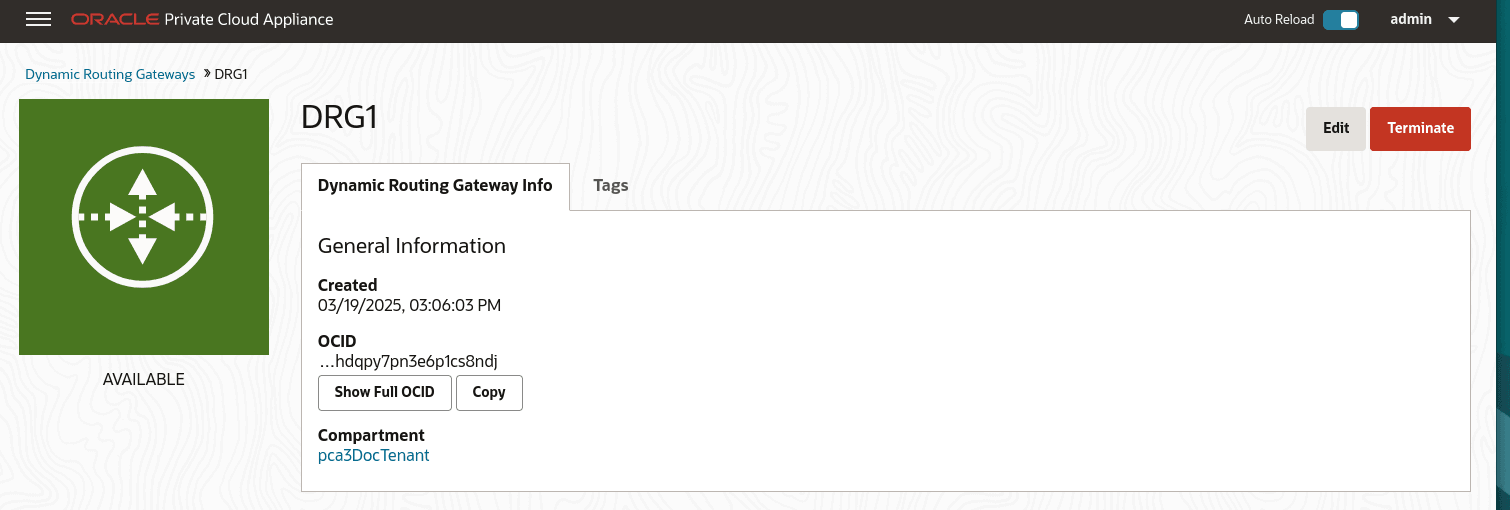
From the Compute Enclave, create a DRG to provide a way for VMs to access the external system. See Create a Dynamic Routing Gateway.
-
From the Compute Enclave, create a Internet Gateway to provide a way for VMs to access the data center switches. See Providing Public Access through an Internet Gateway.

-
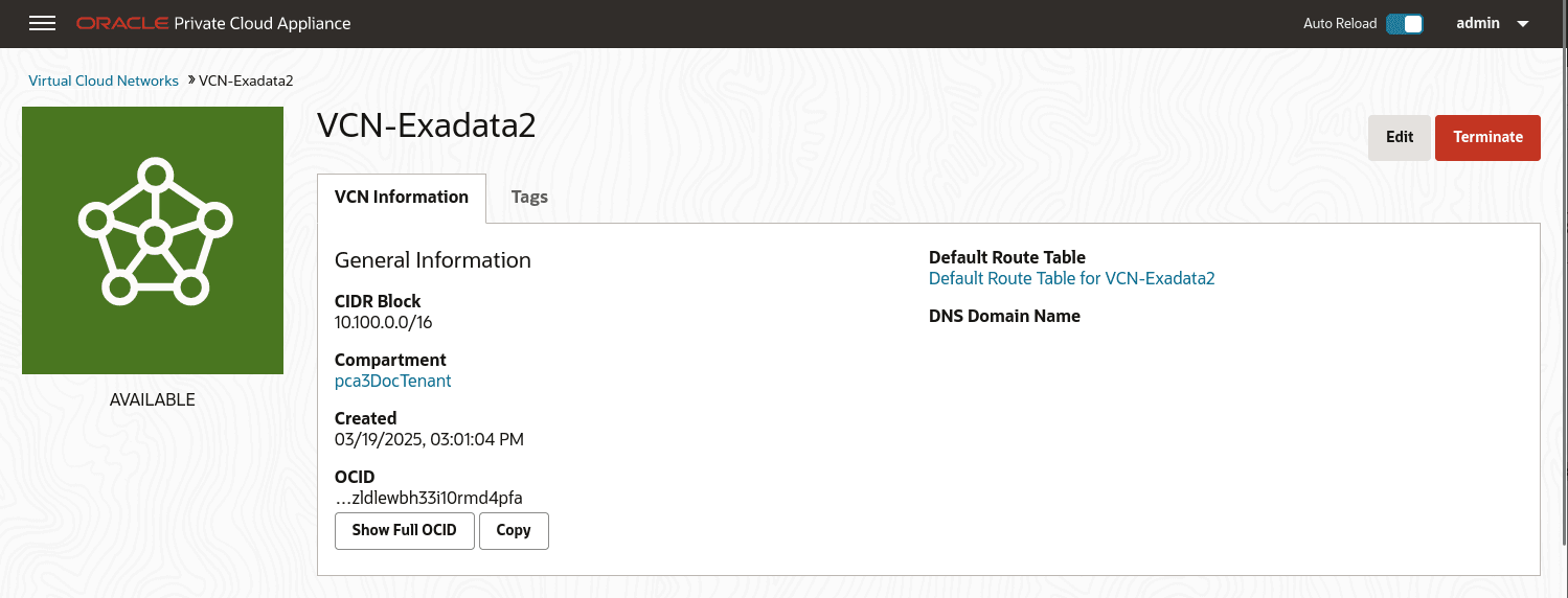
From the Compute Enclave, create VCNs, and Subnets. See Managing VCNs and Subnets.
- Create a VCN for use by the Flex network. In the Compute Web UI, create a VCN. Choose a compartment, a
name for the VCN, then assign a CIDR block that meets your needs.
-
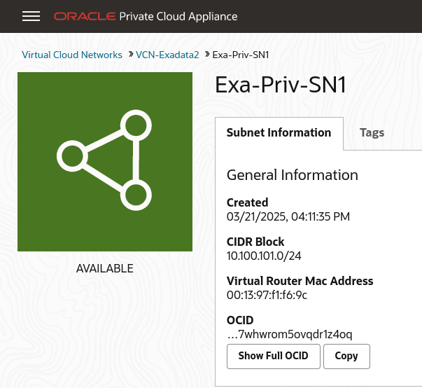
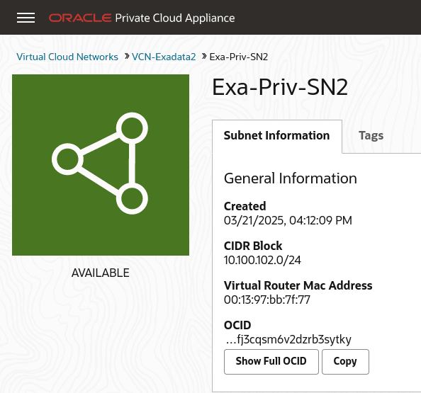
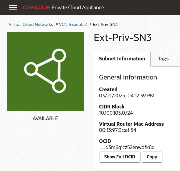
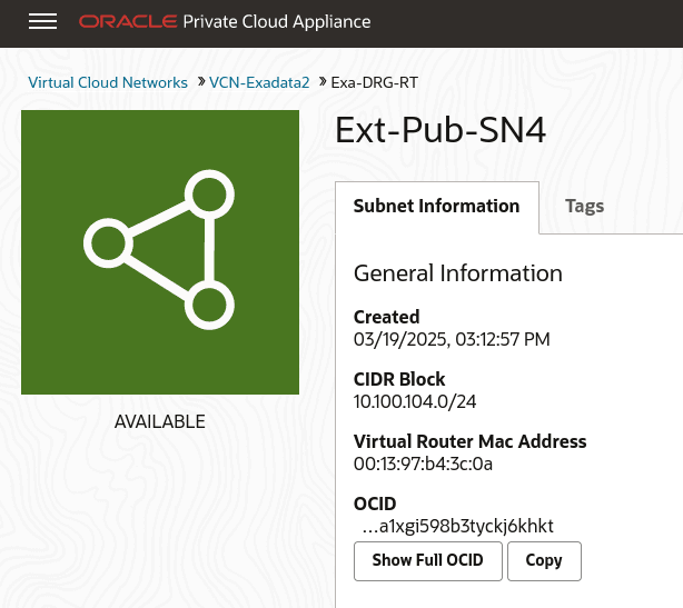
Create subnets within the VCN. Navigate to the VCN in the Compute Web UI, and click Create Subnet. Name the subnet, chose the compartment, and assign a CIDR block within the CIDR block range of the VCN. Next select private or public subnet, then click Create Subnet.
-
Note the OCID of each subnet, you need these OCIDs to enable communication between the VMs and the Flex network in step 5 of this tutorial.
-
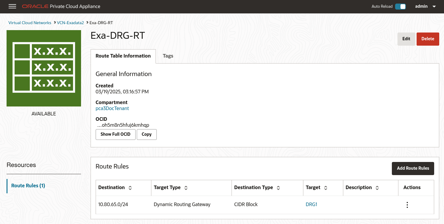
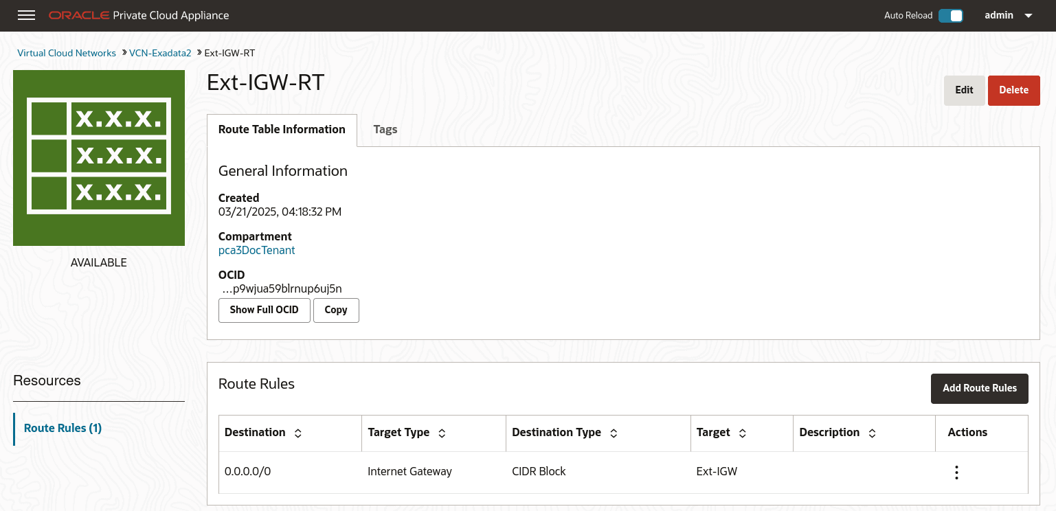
Create Route Tables in the VCN. Route tables are required to send traffic outside the VCN.
Navigate to the VCN in the Compute Web UI, select Route Tables in the Resources menu. Click Create Route Table, type a name for the Route Table and click Create Route Table.
Then create any associated route rules by clicking Add Route Rules and entering a target and the destination CIDR block.
This example shows a route table that directs network traffic for the DRG, and a route table that directs network traffic for the internet gateway.
-
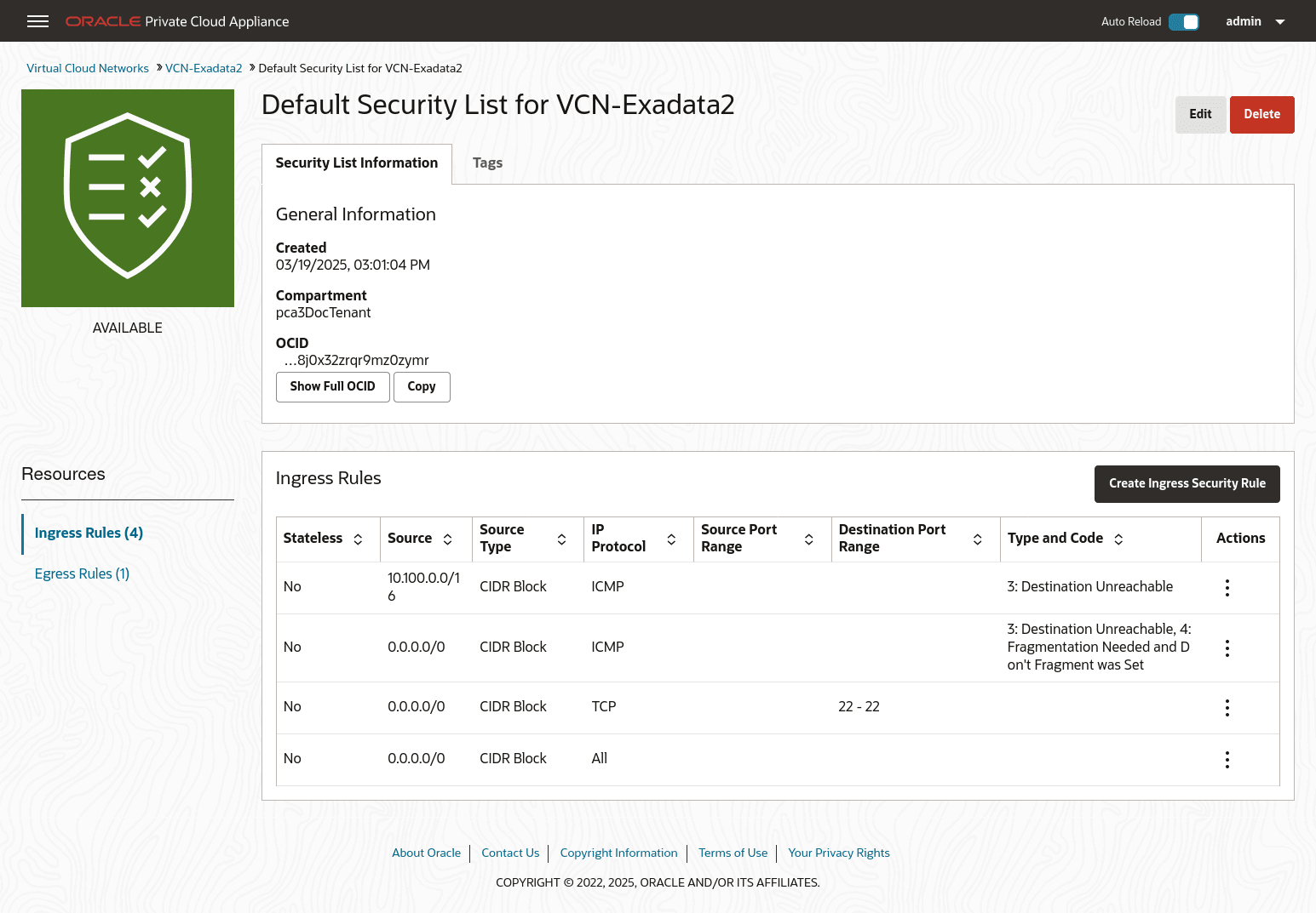
Create Security Lists to enable ingress traffic. See Controlling Traffic with Security Lists.
- Create a VCN for use by the Flex network. In the Compute Web UI, create a VCN. Choose a compartment, a
name for the VCN, then assign a CIDR block that meets your needs.
-
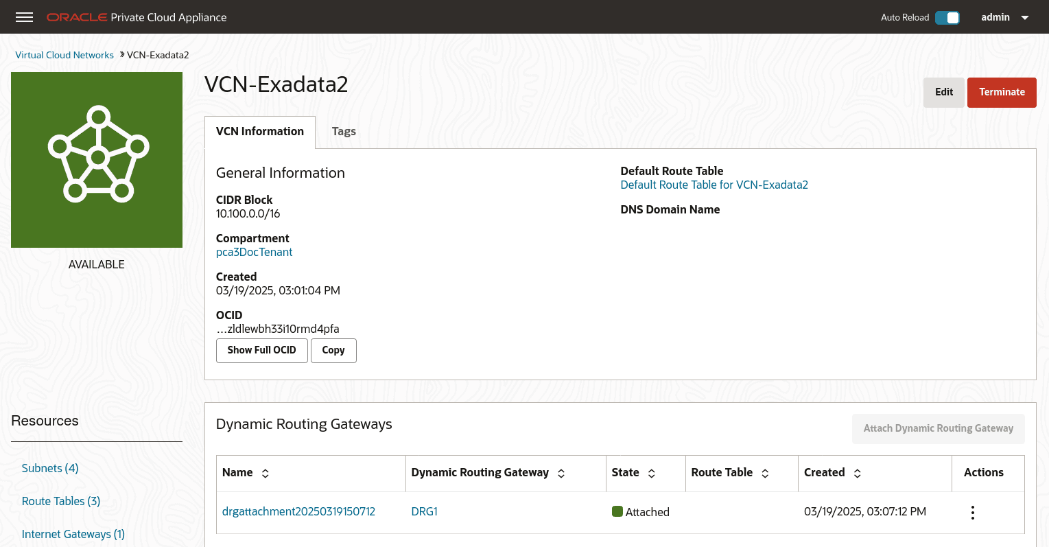
From the Compute Enclave, create DRG-attachments to enable the VCN to use the DRG. See Attach VCNs to a Dynamic Routing Gateway
From the VCN page, select Dynamic Routing Gateway from the left menu, then click Attach Dynamic Routing Gateway. Select the appropriate tenancy, then choose the DRG you want to attach from the dropdown list and click Attach Dynamic Routing Gateway.
-
From the Service CLI, enable communication between the Flex network and the VM subnets.
PCA-ADMIN> flexNetworkEnableAccess flexNetworkId=ocid1.exadata.unique_id \ subnetId=ocid1.subnet.unique_id Command: flexNetworkEnableAccess flexNetworkId=ocid1.exadata.unique_id \ subnetId=ocid1.subnet.unique_id Status: Success Time: 2024-11-17 18:56:45,251 UTC -
Create VMs in the subnets and configure their access. See Compute Instance Deployment
For this example, each private subnet is configured with 2 VNICs: a primary and a secondary. Configure primary VNICs to attach to the public subnet, and seconadry VNICs to attach to the DRG.
When creating an instance, choose the VCN then the subnet. For the public VM, assign a public IP address.
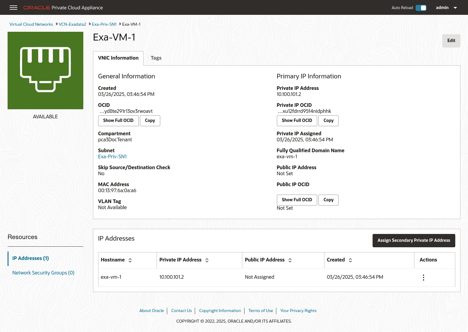
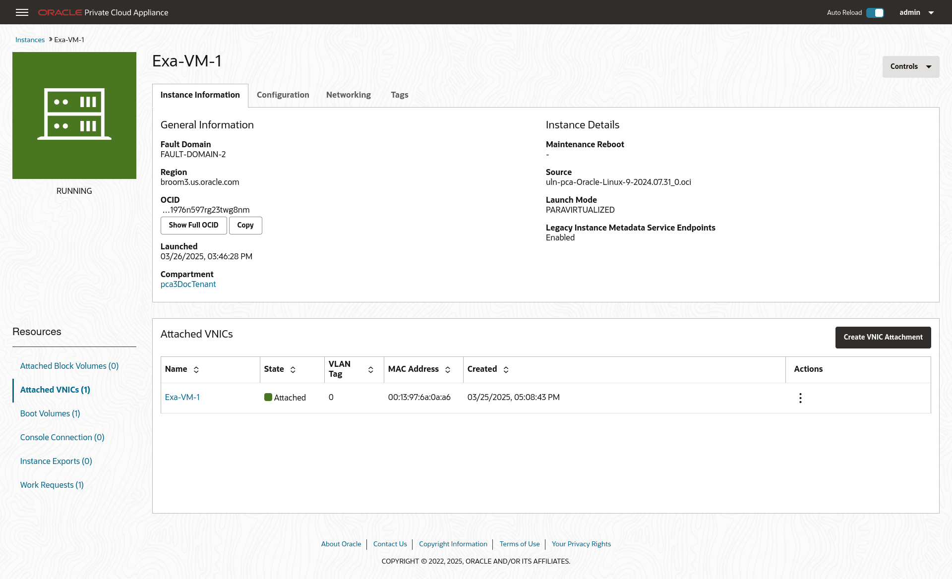
From the Compute Instance page, select the instance. From the Resources menu select Attached VNICs. You will see the primary VNIC. To create the secondary VNIC, click Create VNIC Attachment. Choose the VCN and a subnet. and assign See Creating and Attaching a Secondary VNIC.
Create primary and secondary VNICs for each instance such that the primary VINC attaches to the public subnet, and the secondary VNIC attaches to the DRG.
-
Verify connectivity between the VMs and the external system.