Replacing a Fan Module
Fan modules are located at the back of the server and are replaceable components that do not require you to power off the server for service.
When facing the rear of the system, fan module 0 (FM0) is on the left, fan
module 1 (FM1) is in the center, and fan module 2 (FM2) is
on the right.
Remove and replace only one fan module at a time. Ensure that you have obtained the replacement fan module and that it is ready for installation before starting the replacement procedure.
Caution:
When removing and replacing a fan module in the X10-2c GPU L40S Compute Server, you must complete the entire procedure within 25 seconds to maintain adequate cooling in the system, and prevent the possible shutdown of the server.
Remove a Fan Module
You do not have to power off the server to service fan modules.
-
Remove and replace only one fan module at a time.
When facing the rear of the system, fan module 0 (
FM0) is on the left, fan module 1 (FM1) is in the center, and fan module 2 (FM2) is on the right. -
Identify which fan module requires replacement.
Note:
For accurate component identification, see Illustrated Back Panel Components Breakdown.
Each fan module has one bi-color status indicator (LED) located at the back of the system chassis. If the fan is operating normally, the indicator is lit green. If the fan is faulty, the indicator is lit amber.
Alternatively, to list all known faults in the server, log in to the ILOM service processor from the ILOM Fault Management Shell and issue the
fmadm faultycommand. For more information, refer to "Oracle ILOM User's Guide for System Monitoring and Diagnostics" in the Oracle Integrated Lights Out Manager (ILOM) Documentation. -
Prepare the system for fan module removal.
-
Gain access to the rear of the server where the faulty fan module is located.
-
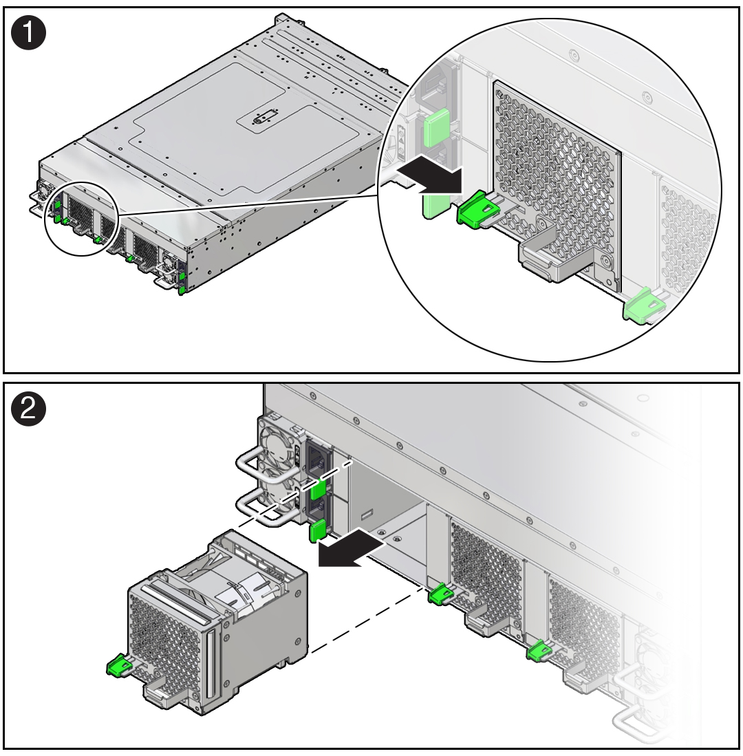
Grasp the fan module handle and use your thumb to push the release latch inwards, toward the handle [1]. Then pull the fan module straight out of the chassis [2].
Note:
If the release lever becomes stuck (it won't move all the way right to the released position), push the lever down as you slide it in toward the module handle. This will help prevent the lever from binding in its slot in the fan module sheet metal.

-
Set the fan module on an antistatic mat.
Install a Fan Module
-
Remove the replacement fan module from its packaging, and place it on an antistatic mat.
-
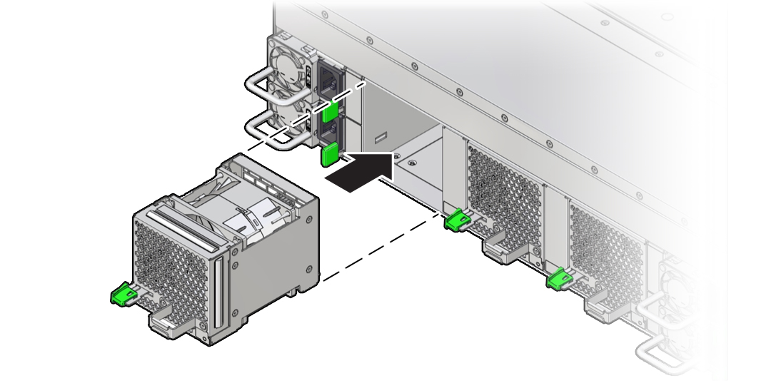
Grasp the replacement fan module by the handle and align it with the empty chassis fan module slot.
The fan modules are keyed to ensure that they are installed in the correct orientation.
-
Slide the fan module into the chassis and apply firm pressure to fully seat the fan module.
You will hear an audible click when the fan module latches.
Note:
If the lever doesn't fully latch closed, pull the lever slightly toward you while pushing the lever up and to the left in order for it to completely latch. This will help keep the lever from binding in its slot in the module sheet metal.

-
Verify that the fan module status indicator (LED) on the replacement fan module is lit green.