7 Expanding a Recovery Appliance Rack with Additional Storage Servers
The Recovery Appliance racks have a flexible configuration that allows a minimum of three storage servers. You can extend a rack up to a total of 18 storage servers for Recovery Appliance RA21, X8M, and X8 through X5. Recovery ApplianceX4 only supports 14 storage servers. All Recovery Appliance racks have two compute servers, regardless of the number of storage servers.
This chapter describes how to expand a Recovery Appliance rack by adding storage servers. It contains the following sections:
Preparing to Extend Recovery Appliance
Before expanding a rack, review the cabling requirements and collect information about the current rack. This section contains the following topics:
Estimating RDMA Network Fabric Cable Path Lengths
Ensure that you have the required number and lengths of the RDMA Network Fabric cables for your installation. Cable paths should be as short as possible. After you calculate the length of a cable path, consider the following ways that the length might increase. Then select the shortest cable to satisfy the length requirement.
Consider the following:
-
Bends in the cable path increase the required length of the cable. A cable rarely travels in a straight line from connector to connector. Bends in the cable path are necessary, and each bend increases the total length.
-
Bundling increases the required length of the cables. Bundling causes one or more cables to follow a common path. However, the bend radius is different in different parts of the bundle. If the bundle is large and unorganized, and there are many bends, one cable might bend only on the inner radius, while another cable might bend only on the outer radius. In this situation, the difference in the required cable lengths is substantial.
-
If you are routing the RDMA Network Fabric cable under the floor, consider the height of the raised floor when calculating the cable path length.
Obtaining the Current Configuration Information
Use the current configuration of the Recovery Appliance rack to plan patching requirements, configure new IP addresses, and so on.
Log into the first compute server in the rack and collect the following information:
-
The
exachkreport for the rack. See My Oracle Support Doc ID 1070954.1 for information about theexachkutility. -
Image history information. Use the following command:
# dcli -g ~/all_group -l root "imagehistory" > imagehistory.txt
-
Current IP addresses of all storage servers and compute servers. Use the following command:
# dcli -g ~/all_group -l root "ifconfig" > ifconfig_all.txt
-
Configuration of the storage servers, disks, flash logs, and IORM plans. Use the following commands:
# dcli -g ~/cell_group -l root "cellcli -e list cell detail" > cell_detail.txt

# dcli -g ~/cell_group -l root "cellcli -e list physicaldisk detail" >   \
physicaldisk_detail.txt

# dcli -g ~/cell_group -l root "cellcli -e list griddisk attributes name,offset,size,status,asmmodestatus,asmdeactivationoutcome" > griddisk.txt

# dcli -g ~/cell_group -l root "cellcli -e list flashcache detail" > fc_detail.txt

# dcli -g ~/cell_group -l root "cellcli -e list flashlog detail" > fl_detail.txt

# dcli -g ~/cell_group -l root "cellcli -e list iormplan detail" > iorm_detail.txt
-
HugePages memory configuration on the compute servers. Use the following command:
dcli -g ~/dbs_group -l root "cat /proc/meminfo | grep 'HugePages'" > hugepages.txt
-
InfiniBand switch information. Use the following command:
# ibswitches > ibswitches.txt
-
Firmware version of the Sun Datacenter InfiniBand Switch 36 switches. Use the
nm2versioncommand on each switch. -
The following network files on the first compute server in the rack:
-
/etc/resolv.conf -
/etc/ntp.conf -
/etc/network -
/etc/sysconfig/network-scripts/ifcfg-*
-
-
Any users, user identifiers, groups, and group identifiers created for cluster-managed services that must be created on the new servers:
-
/etc/passwd -
/etc/group
-
-
The current cluster status. Use the following command:
# crsctl stat res -t > crs_stat.txt
-
Patch information from the Grid Infrastructure and Oracle homes. Use the following commands as the Grid Infrastructure home owner and the Oracle home owner:
/u01/app/oracle/product/11.2.0/dbhome_1/OPatch/opatch lsinventory -oh    \
GRID_HOME -detail -all_nodes > opatch_grid.txt

/u01/app/oracle/product/11.2.0/dbhome_1/OPatch/opatch lsinventory -oh    \
ORACLE_HOME -detail -all_nodes >> opatch_oracle.txt
In the preceding commands, GRID_HOME is the path of the Grid Infrastructure home directory, and ORACLE_HOME is the path of the Oracle home directory.
Generating the Network Configuration Files
Use the Oracle Exadata Deployment Assistant to list the IP addresses for the new servers. Specify only the number of new servers. Define all other items, such as the Oracle home location and owner, the same as the existing rack configuration. In particular, the bonding configuration of the new servers must match the existing servers in the rack. The Oracle Exadata Deployment Assistant InfiniBand Network Configuration Page enables you to select the type of bonding.
You must install the Recovery Appliance software in the new storage servers, after installing them in the rack.
Moving the Audit and Diagnostic Files
Move to delete files in the $GRID_HOME/rdbms/audit directory and the $GRID_HOME/log/diagnostics directory before extending a cluster. Oracle recommends doing this task a day or two before the planned extension to allow sufficient time.
Synchronizing Release and Patch Levels
The servers probably have a later release or patch level than the rack where they will be added. You can either update the rack to the later release or reimage the new servers to match the current rack. In either case, ensure that all servers, and all Sun Datacenter InfiniBand Switch 36 switches, are at the same patch level.
Also consider how to handle the Grid Infrastructure and database home releases and bundle patch updates. If you plan to apply the new patches, then Oracle recommends upgrading the existing servers, so that the new servers inherit the releases as part of the extension procedure. Then fewer servers are patched. Apply the patches to the existing servers in advance, thereby reducing the total amount of work required during the extension.
Precautions and Guidelines
This section lists safety precautions and guidelines for handling the equipment. Familiarize yourself with this information before extending the rack:
General Safety Precautions
Read the following safety guidelines before working on a Recovery Appliance rack:
-
Important Safety Information for Sun Hardware Systems shipped with the rack
-
Zero Data Loss Recovery Appliance Safety and Compliance Guide for safety notices
InfiniBand Cable Precautions
Review the following InfiniBand cable precautions before working with InfiniBand cables:
-
Fiber optic InfiniBand cables with laser transceivers must be type Class 1.
-
Do not allow any copper core InfiniBand cable to bend to a radius tighter than 127 mm (5 inches). Tight bends can damage the cables internally.
-
Do not allow an optical InfiniBand cable to bend to a radius tighter than 85 mm (3.4 inches). Tight bends can damage the cables internally.
-
Do not use zip ties to bundle or support InfiniBand cables. The sharp edges of the ties can damage the cables internally. Use hook-and-loop straps.
-
Do not subject an InfiniBand cable to extreme tension. Do not pull or drag it. Pulling on an InfiniBand cable can damage it internally.
-
Unroll the full length of an InfiniBand cable.
-
Do not twist an InfiniBand cable more than one revolution over its entire length. Twisting an InfiniBand cable can damage it internally.
-
Do not route InfiniBand cables where they can be stepped on or rolled over. Crushing can damage the cable internally.
InfiniBand Cable Bundling Guidelines
When bundling InfiniBand cables in groups, use hook-and-loop straps to keep the cables organized. If possible, use color-coordinated straps to help identify the cables and their routing. The InfiniBand splitter and 4X copper conductor cables are thick and heavy for their length. Consider the retention strength of the hook-and-loop straps when supporting cables. Bundle as few cables as reasonably possible. Oracle recommends that no more than eight cables be bundled together.
If the InfiniBand cables break free of their straps and fall, then they might break internally from striking the floor or from sudden changes in tension. Place the hook-and-loop straps as close together as reasonably possible, for example, one strap every foot (0.3 m). If a cable breaks free from a strap, then the cable cannot fall far before it is supported by another strap.
Cable Management Arm Guidelines
Review the following cable management arm (CMA) guidelines before routing the cables:
-
Remove all required cables from the packaging, and allow cables to acclimate or reach operating temperature, if possible. This improves the ability to manipulate the cables.
-
Label both ends of each cable using a label stock that meets the ANSI/TIA/EIA 606-A standard, if possible.
-
Begin the installation procedure in ascending order.
-
Only slide out one server at a time. Sliding out more than one server can cause cables to drop or cause problems when sliding the servers back.
-
Separate the installation by dressing cables with the least stringent bend radius requirements first. The following bend radius requirements are based on EIA/TIA 568-x standards, and may vary from the manufacturer's requirements:
-
CAT5e UTP: 4 x diameter of the cable or 1 inch/25.4 mm minimum bend radius
-
AC power cables: 4 x diameter of the cable or 1 inch/ 25.4 mm minimum bend radius
-
TwinAx: 5 x diameter of the cable or 1.175 inch/33 mm.
-
Quad Small Form-factor Pluggable (QSFP) InfiniBand cable: 6 x diameter of the cable or 2 inch/55 mm.
-
Fiber core cable: 10 x diameter of the cable or 1.22 inch/31.75 mm for a 0.125 cable.
-
-
Install the cables with the best longevity rate first.
Adding Storage Servers to a Rack
The following sections describe how add storage servers to a Recovery Appliance rack:
Note:
-
Apply any patches to the switches and servers in the rack before extending the hardware.
-
You can extend the hardware while Recovery Appliance is online, and with no downtime. However, take extreme care.
Checking the Recovery Appliance Rack
Examine the Recovery Appliance physical systems for any problems:
-
Check the rack for damage.
-
Check the rack for loose or missing screws.
-
Check Recovery Appliance for the ordered hardware configuration.
-
Check that all cable connections are secure and well seated.
-
Check the power cables.
-
Ensure that the correct connectors were supplied for the data center facility power source.
-
Check the network data cables.
-
Check the site location tile arrangement for cable access and airflow.
-
Check the data center airflow into the front of Recovery Appliance.
Unpacking and Labeling the New Storage Servers
The Recovery Appliance racks are supplied with the InfiniBand and Cat5e harness connections for the maximum number of storage servers.
To prepare the new servers for installation:
Figure 7-1 shows the components of the server expansion kit.
Figure 7-1 Server Expansion Kit Components
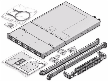
Description of "Figure 7-1 Server Expansion Kit Components"
Note:
All new equipment receives a Customer Support Identifier (CSI), including the new equipment for Recovery Appliance. Contact Oracle Support Services to reconcile the new CSI with the existing CSI for the Recovery Appliance rack. You must have the original instance or serial numbers and the new numbers when contacting Oracle Support Services.
Recovery Appliance RA21, X8M, and X8 through X5 Population Rules
When adding servers to a Recovery Appliance RA21, X8M, or X8 through X5 rack, follow the population rules listed in Table 7-1.
Table 7-1 Recovery Appliance RA21, X8M, and X8 through X5 Rack Population Rules
| Install Order | Rack Units | Rule |
|---|---|---|
|
1 |
U08 to U15 |
Populate toward the top of the rack (4 units) |
|
2 |
U27 to U40 |
Populate toward the top of the rack (7 units) |
|
3 |
U26 to U23 |
Populate toward the bottom of the rack (2 units) |
|
4 |
U19 to U18 |
(1 unit) |
|
5 |
U41 to U42 |
(1 unit) |
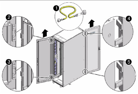
Removing the Doors
To remove the doors on the Recovery Appliance rack:
-
Remove the front and rear doors, as follows:
-
Unlock the front and rear doors. The keys are in the shipping kit.
-
Open the doors.
-
Detach the grounding straps connected to the doors by pressing down on the tabs of its quick-release connectors, and pull the straps from the frame.
-
Lift the doors up and off their hinges.
Description of the callouts in Figure 7-2:
1: Detaching the grounding cable
2: Top rear hinge
3: Bottom rear hinge
4: Top front hinge
5: Bottom front hinge
-
-
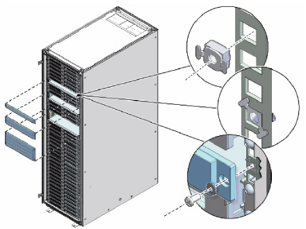
To remove the filler panels where the servers will be installed, use a No. 2 screwdriver to remove the M6 screws. The number of screws depends on the type of filler panel. Save the screws for future use.
Note:
If you are replacing the filler panels, then do not remove the Duosert cage nuts from the Radio Electronics Television Manufacturers Association (RETMA) rail holes.
Adding New Servers
You can extend Recovery Appliance X7, X6, or X5 to a maximum of 18 storage servers and Recovery Appliance X4 to a maximum of 14 storage servers. You can add any number of storage servers at a time, from one to 15 servers when starting with a minimum configuration.
To prepare for the installation:
-
Identify the rack unit where you will install the server. Fill the first available unit, starting from the bottom of the rack.
See "Recovery Appliance X8, X7, X6, and X5 Rack Layout" or "Recovery Appliance X4 Rack Layout", as applicable.
-
Remove and discard the trough, which attaches the cable harness when no server is installed in the unit.
-
Remove and discard the solid filler.
To install the rail assembly:
-
Position a mounting bracket against the chassis so that the slide-rail lock is at the server front, and the five keyhole openings on the mounting bracket are aligned with the five locating pins on the side of the chassis.
-
Orient the slide-rail assembly so that the ball-bearing track is forward and locked in place.
-
Starting on either side of the rack, align the rear of the slide-rail assembly against the inside of the rear rack rail, and push until the assembly locks into place with an audible click.
Figure 7-5 Aligning the Side-Rail Assembly With the Rack
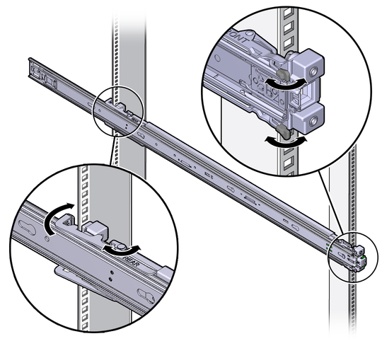
Description of "Figure 7-5 Aligning the Side-Rail Assembly With the Rack" -
Align the front of the slide-rail assembly against the outside of the front rack rail, and push until the assembly locks into place and you hear the click.
WARNING:
-
Installing a server requires a minimum of two people or a lift because of the weight of each server. Attempting this procedure alone can result in equipment damage, personal injury, or both.
-
Extend the rack anti-tip bar to prevent the rack from tipping during equipment installation.
-
For Recovery Appliance X4 racks, load the servers from the bottom up, so that the rack does not become top-heavy and tip over. See "Recovery Appliance X4 Rack Layout" for the designated location of each server.
-
For Recovery Appliance X6 or X5 racks, load the servers following the population rules. See "Recovery Appliance RA21, X8M, and X8 through X5 Population Rules".
To install the server:
-
Read the service label on the top cover of the server before installing a server into the rack.
-
Push the server into the slide rail assembly:
-
Push the slide rails into the slide rail assemblies as far as possible.
-
Position the server so the rear ends of the mounting brackets are aligned with the slide rail assemblies mounted in the equipment rack.
Figure 7-6 Inserting the Server with Mounting Brackets into the Slide Rails
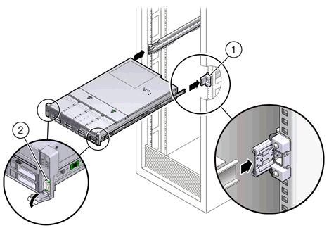
Description of "Figure 7-6 Inserting the Server with Mounting Brackets into the Slide Rails"Figure 7-6 callouts highlight the following:
1: Mounting bracket inserted into slide rail
2: Slide-rail release lever
-
Insert the mounting brackets into the slide rails, and push the server into the rack until the mounting brackets encounter the slide rail stops, approximately 30 cm (12 inches).
-
Simultaneously push down and hold the slide rail release levers on each mounting bracket while pushing the server into the rack.
-
Continue pushing until the slide rail locks on the front of the mounting brackets engage the slide rail assemblies, and you hear the click.
-
-
Cable the new server as described in "Cabling the Storage Servers".
Note:
Oracle recommends that two people push the servers into the rack: one person to move the server in and out of the rack, and another person to watch the movement of the cables and the CMA.
See Also:
"Installing the Server Into a Rack" in Sun Server X4-2L Installation Guide at
http://docs.oracle.com/cd/E36974_01/html/E38145/z4000087165586.html#scrolltoc
Cabling the Storage Servers
After installing the new storage servers, cable them to the existing equipment.
Note:
-
The existing cable connections in the rack do not change.
-
The blue cables connect to the compute servers, and the black cables connect to the storage servers. These network cables are for the NET0 Ethernet interface port.
-
Attach and route the management cables on the CMA and rear panel for one server at a time. Do not slide out multiple servers.
-
Start from the bottom of the rack, and work upward.
-
Longer hook and loop straps are needed when cabling three CAT5e cables or two twinaxial cables.
To cable the new servers in the rack:
-
Install the cable management arm (CMA):
-
Into the left slide rail, slide CMA connector A until it locks into place with an audible click.
-
Into the right slide rail, slide CMA connector B until it locks into place with an audible click. Then do the same with CMA connector C.
-
-
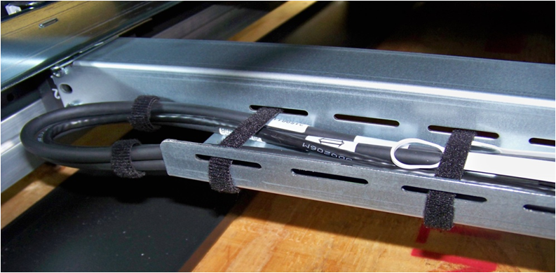
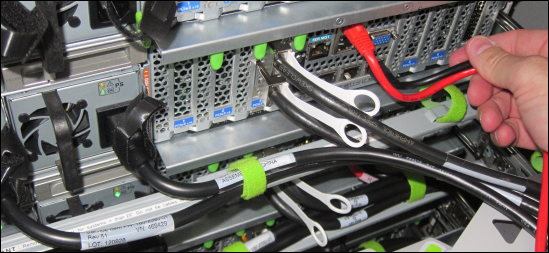
Insert the cables into their ports through the hook and loop straps, then route the cables into the CMA in this order:
-
Power
-
Ethernet
-
InfiniBand
-
-
Route the cables through the CMA and secure them with hook and loop straps on both sides of each bend in the CMA.
-
Close the crossbar covers to secure the cables in the straightaway.
-
Verify operation of the slide rails and the CMA for each server:
Note:
Oracle recommends that two people do this step: one person to move the server in and out of the rack, and another person to watch the movement of the cables and the CMA.
-
Slowly pull the server out of the rack until the slide rails reach their stops.
-
Inspect the attached cables for any binding or kinks.
-
Verify that the CMA extends fully from the slide rails.
-
-
Push the server back into the rack:
-
Release the two sets of slide rail stops.
-
Locate the levers on the inside of each slide rail, just behind the back panel of the server. They are labeled PUSH.
-
Simultaneously push in both levers and slide the server into the rack, until it stops in approximately 46 cm (18 inches).
-
Verify that the cables and CMA retract without binding.
-
Locate the slide rail release buttons near the front of each mounting bracket.
-
Simultaneously push in both slide rail release buttons and slide the server completely into the rack, until both slide rails engage.
-
-
Dress the cables, and then tie off the cables with the straps. Oracle recommends that you dress the InfiniBand cables in bundles of eight or fewer.
-
Slide each server out and back fully to ensure that the cables are not binding or catching.
-
Repeat the procedure for all servers.
-
Connect the power cables to the power distribution units (PDUs). Ensure the breaker switches are in the OFF position before connecting the power cables. Do not plug the power cables into the facility receptacles now.
See Also:
-
"Install the Second-Generation Cable Management Arm" in Sun Server X4-2L Installation Guide at
http://docs.oracle.com/cd/E36974_01/html/E38145/z40000151427029.html#scrolltoc
Closing the Rack
To close the rack after installing new equipment:
-
Replace the rack front and rear doors:
-
Retrieve the doors and place them carefully on the door hinges.
-
Connect the front and rear door grounding strap to the frame.
-
Close the doors.
-
(Optional) Lock the doors. The keys are in the shipping kit.
-
-
(Optional) Replace the side panels, if they were removed for the upgrade:
-
Lift each side panel up and onto the side of the rack. The top of the rack can support the weight of the side panel. Ensure that the panel fasteners line up with the grooves in the rack frame.
-
Turn each side panel fastener 1/4 turn clockwise using the side panel removal tool. Turn the fasteners next to the panel lock clockwise. There are 10 fasteners per side panel.
-
(Optional) Lock each side panel. The key is in the shipping kit. The locks are located on the bottom center of the side panels.
-
Connect the grounding straps to the side panels.
-
After closing the rack:
-
If you are installing a new system, proceed to "Installing the Software on Recovery Appliance"
-
If you added the server to increase storage on an existing system, proceed to "Making New Storage Available"
Making New Storage Available
After you add storage servers to a rack to increase the storage capacity of an existing system, you must run racli commands to make the additional storage available for backups.
Caution:
After you add a storage cell to the Recovery Appliance, you cannot remove it.On install by default, a DELTA disk group name is created and the storage location name, which is often identical to the disk group name (DELTA, DELTA1, etc.). However the disk group name and storage location name are two different things. Storage is expanded using the UPDATE_STORAGE_LOCATION command.
Note:
The default storage location and the ASM disk group are both called DELTA, but are not the same thing.
-
The new storage cells have the same Exadata image version as the existing storage cells.
-
The new storage cells do not have any associated databases. (You can run
cellcli -e list databaseto verify this is the case.) -
The root password of the new storage cell must still be the factory default.
To make the new storage available:
See Also:
-
RACLI Overview for details about the commands used in the procedure.
-
Zero Data Loss Recovery Appliance Administrator’s Guide for information on how to view storage location information.
