Recovery Appliance RA21 Rack Layout
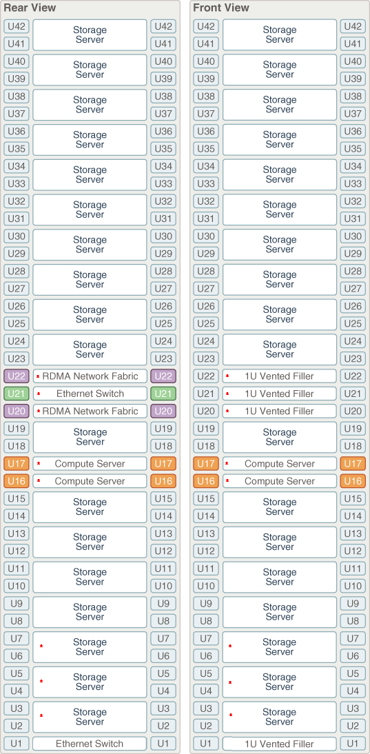
Figure 15-1shows the front and rear views of a Recovery Appliance RA21 full rack. The front is shown on the left, and the rear is shown on the right. The red bullet next to a component means that it is required for all Recovery Appliances.
Figure 15-1 Rack Layout of the Recovery Appliance RA21 Full Rack

Description of "Figure 15-1 Rack Layout of the Recovery Appliance RA21 Full Rack"
Note:
The 1U empty space at the bottom of the rack is reserved for an optional spine switch, which is used in multi-rack installations. Do not install any other unit in this space.
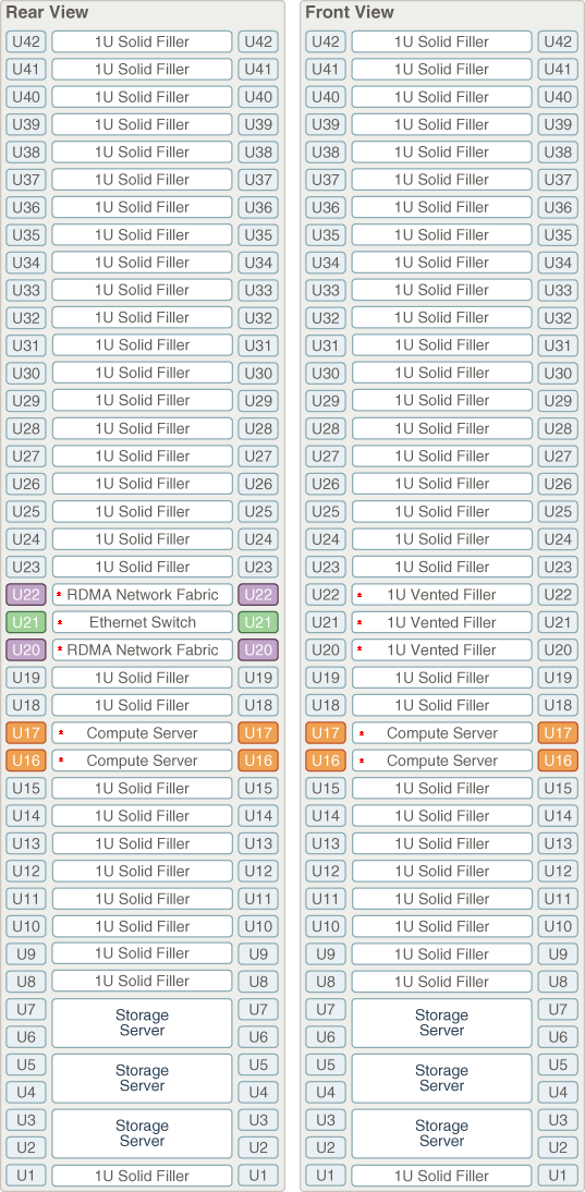
Figure 16-2 shows the front and rear views of a Recovery Appliance RA21 minimum configuration.
Figure 15-2 Rack Layout of the Recovery Appliance RA21 Minimum Configuration

Description of "Figure 15-2 Rack Layout of the Recovery Appliance RA21 Minimum Configuration"