Recovery Appliance X8, X7, X6, and X5 Rack Layout
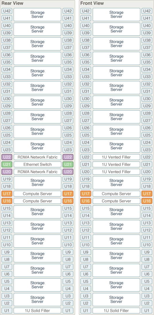
Figure 19-1 shows the front and rear views of a Recovery Appliance X8, X7, X6, or X5 full rack. The front is shown on the left, and the rear is shown on the right.
Note:
The 1U empty space at the bottom of the rack is reserved for an optional InfiniBand spine switch, which is used in multirack installations. Do not install any other unit in this space.
Figure 19-1 Rack Layout of the Recovery Appliance X8, X7, X6, or X5 Full Rack

Description of "Figure 19-1 Rack Layout of the Recovery Appliance X8, X7, X6, or X5 Full Rack"
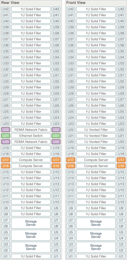
Figure 19-2 shows the front and rear views of a Recovery Appliance X8, X7, X6, or X5 minimum configuration.
Figure 19-2 Rack Layout of the Recovery Appliance X8, X7, X6, or X5 Minimum Configuration

Description of "Figure 19-2 Rack Layout of the Recovery Appliance X8, X7, X6, or X5 Minimum Configuration"