Understanding Multi-Rack Cabling for Racks with InfiniBand Network Fabric
Up to eight racks can be cabled together without external RDMA Network Fabric switches.
Three RDMA Network Fabric switches are needed when cabling racks together. If any rack does not include a third switch, then order the expansion switch kit. These switches attach to standard RDMA Network Fabric connectors at the end of the cables. The procedures in this section assume the racks are adjacent to each other. If they are not, then longer cables may be required for the connections.
Note:
Only for InfiniBand Network Fabric (X8 and earlier).
-
For Eighth or Quarter Racks, which are the smallest Elastic Configurations, follow the instructions in Cabling Oracle Exadata Quarter Racks and Oracle Exadata Eighth Racks with InfiniBand Network Fabric for direct connection without spine switch.
-
For other racks (Half Rack, Full Rack, Elastic Configurations larger than Eighth or Quarter Rack) install a spine switch and follow the standard N-rack cabling for two or more interconnected racks, for example Two-Rack Cabling with InfiniBand Network Fabric.
The switch at rack unit 1 (U1) is referred to as the spine switch.
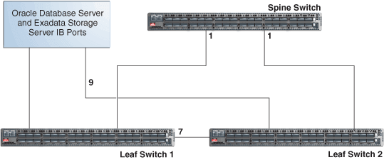
In a single rack, the two leaf switches are interconnected using seven connections. In addition, each leaf switch has one connection to the spine switch. The leaf switches connect to the spine switch as shown in the following graphic:
Figure 24-1: Connections Between Spine Switch and Leaf Switches in a Single Rack
Description of the illustration dbmog_vm_037.png
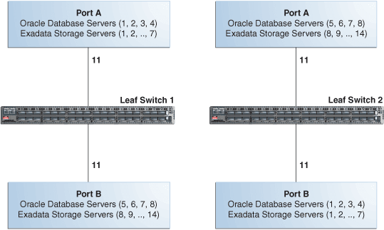
The Oracle Database servers and Exadata Storage Servers connect to the leaf switches as shown in the following graphic:
Figure 24-2: Connections Between Database Servers and Storage Servers and Leaf Switches
Description of the illustration dbmog_vm_036.png
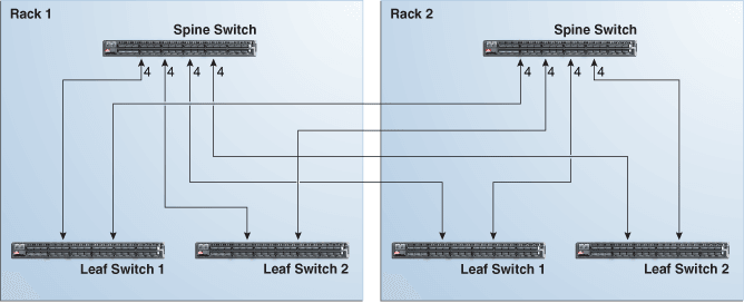
When connecting up to eight racks together, remove the seven existing inter-switch connections between each leaf switch, as well as the two connections between the leaf switches and the spine switch. From each leaf switch, distribute eight connections over the spine switches in all racks. In multi-rack environments, the leaf switches inside a rack are no longer directly interconnected, as shown in the following graphic:
Figure 24-3: Connections Between Spine Switches and Leaf Switches Across Two Racks
Description of the illustration dbmog_vm_038.png
As shown in the preceding graphic, each leaf switch in rack 1 connects to the following switches:
-
Four connections to its internal spine switch
-
Four connections to the spine switch in rack 2
The spine switch in rack 1 connects to the following switches:
-
Eight connections to both internal leaf switches
-
Eight connections to both leaf switches in rack 2
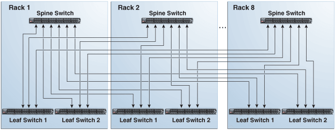
As the number of racks increases from two to eight, the pattern continues as shown in the following graphic:
Figure 24-4: Connections Between Spine Switches and Leaf Switches for up to 8 Racks
Description of the illustration dbmog_vm_029.png
As shown in the preceding graphic, each leaf switch has eight inter-switch connections distributed over all spine switches. Each spine switch has 16 inter-switch connections distributed over all leaf switches. The leaf switches are not directly interconnected with other leaf switches, and the spine switches are not directly interconnected with the other spine switches.
Note: Cable lengths are specified for racks 1 through 8.