B Setting Up a Virtual Network TAP and L2TP Tunnel
This appendix provide information on capturing ethernet traffic on a web server instance and transporting it to the instance with the RUEI NPA Collector using a Virtual Ethernet Network TAP and a Layer 2 Tunneling Protocol (L2TP) tunnel. This is achieved using standard Linux kernel network functions and userspace tooling.
Before you begin
Real User Experience Insight (RUEI) performs advanced real-time analysis by its Network Protocol Analyzer (NPA) Collector on ethernet network traffic, to monitor communication between clients(browsers) and webservers.
Traditionally Switch Port Analyzer (SPAN) ports on physical network switches, or physical network Terminal Access Point (TAP) devices were deployed to, non-intrusively, mirror ethernet network traffic to the NPA Collector.
There is no requirement by the NPA Collector on how it receives a mirror of ethernet traffic, as long as the mirror contains all ethernet packets unchanged. However, in cloud environments, for example with heavily virtualized networks, capturing ethernet traffic using physical devices may not be feasible or possible, and therefore requires a different approach.
This appendix describes a best practice, developed over the years, to capture ethernet traffic on web application servers and transport the captured traffic over the network to the RUEI NPA Collector, using a Virtual Ethernet Network TAP and a Layer 2 Tunneling Protocol (L2TP) tunnel:
- Virtual Ethernet Network TAP: Traffic mirror using the Linux Traffic Control (TC) framework.
- Ethernet Tunnel: Transport of mirrored traffic over the network to the NPA Collector using L2TP
This best practice is achieved using standard Linux kernel network functions and userspace tooling. The following set of RPM packages provides an easy-to-use set of tools to manage Virtual TAPs and L2TP tunnels,
- ux-tunnel-transmit
- ux-tunnel-receive
Note:
Please note that similar restrictions in this context applies to the traditional deployment using physical TAPs, described in TAPs in the Oracle Real User Experience Insight Installation Guide, to the virtual TAPs. Which means that, e.g., high network latencies or saturated network can cause packet loss and/or heavy re-ordering, affecting the reporting accuracy.
Prerequisites
- System with RUEI installed (Which includes the RUEI NPA Collector)
- One or more running Web Application Servers with a deployed application (remote system)
- Network connectivity between both systems
- Remote Secure Shell (SSH) access to both systems
- Root / super user (sudo) access on both systems
- Sufficient network bandwidth to tunnel the captured network traffic
- Virtual TAP / Transmit side:
- Oracle Linux 7
- iproute
- iproute-tc (when using iproute version 5)
- bridge-utils
- veth kernel module
- bridge kernel module
- L2TP kernel module
- UEK kernel version
- UEK4 update 7
- UEK5 update 1
It is possible to monitor SSL (HTTPS) protected web application servers. Please note that the NPA Collector is not capable of monitoring ephemeral based cipher suites. In that case, configure the SSL off-loader to use non-ephemeral cipher suites.
Architecture
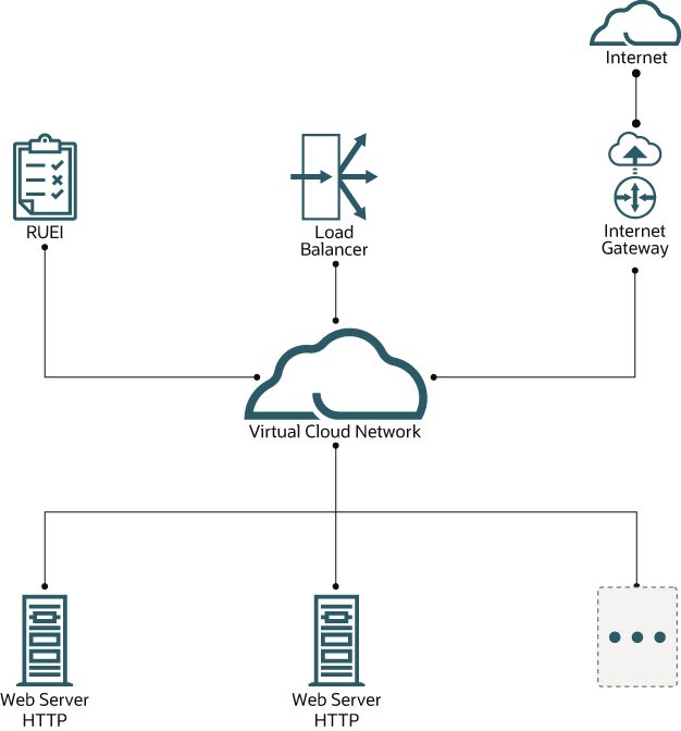
A common deployment architecture contains a load balancer in front of several HTTP web servers. Browsers will connect via an Internet Gateway with a Load Balancer within a Virtual Cloud Network. The Load Balancer may perform SSL encryption and decryption. The Load Balancer forwards the HTTP requests, to one of the Web Servers in the backend set.
On each backend Web Server, using a Virtual Ethernet TAP, HTTP requests are mirrored and sent over the L2TP tunnel to the RUEI instance. The RUEI instance handles multiple tunnels concurrently.

Step-by-Step Configuration
Repeat the instructions in this appendix for each web server instance or load balancer instance you want to monitor. The RUEI instance is capable of handling multiple tunnels concurrently.
Note:
Commands in the following configuration steps must be run as root user or using SUDO.Step 1: Configure Firewalls
Network Firewalls
After the ethernet traffic is captured by the Virtual Network Ethernet TAP on the web application server system, it will be tunneled over L2TP to the RUEI system.
The network should allow L2TP traffic from the web application system to the RUEI system.
Please update all firewalls in the involved networks to allow L2TP traffic: IP protocol 115.
Warning: L2TP has IP protocol number: 115 Please note that L2TP is a protocol on top of IP and not on top of TCP(/IP). An often made mistake is that TCP (and/or UDP) port number115 is incorrectly enabled in security lists, while instead IP protocol number 115 should be enabled.
Linux Firewalls on Both RUEI and Web Application Server Systems
Firewall RUEI System
Note:
When using OCI Marketplace, the RUEI system firewall is already configured to allow L2TP.
To allow L2TP traffic flowing into the RUEI system, enable the following rules in the firewall. For example, when using native Oracle Linux firewalld:
firewall-cmd --zone=public --add-protocol=115
firewall-cmd --zone=public --add-protocol=115 --permanent
Firewall Web Application Server
In general the Oracle Linux firewall allows / trusts all traffic originating from the local machine, flowing out into the network. In case the system has restrictions on the output flows, use the following command on the web application server to allow L2TP traffic:
firewall-cmd --direct --add-rule ipv4 filter OUTPUT 0 -p l2tp -j ACCEPT
firewall-cmd --permanent --direct --add-rule ipv4 filter OUTPUT 0 -p l2tp -j ACCEPT
Step 2: Set Up the RUEI Virtual Ethernet TAP and L2TP Tunnel
L2TP Tunnel on RUEI
Preparation
The L2TP tunnel configuration requires the proper tunnel source and destination endpoint IPs. All instructions in this chapter must be performed on the RUEI instance, using SSH, unless otherwise instructed.
Source IP (local, RUEI)
ip address showSample Output: 10.10.10.10
Destination IP (remote, web server)
Determine the L2TP tunnel destination IP using:
host <dns-name-WEBSERVER>Sample Output: 10.10.10.11
Caution
When the WEBSERVER is behind Network Address Translation (NAT), not its locally configured IP (as can be determined using ip address show on the WEBSERVER instance) must be used, but the NAT address must be used. Using the host (DNS resolve) command, as above, provides the correct IP address in most circumstances.
Install L2TP Tunnel on RUEI
Run the following command as the root user:
cd /root/ruei
./ruei-install.sh rpms/ux-tunnel-receive-*.rpm
Note:
When using OCI Marketplace, the RPM is already installed.
Setup
Configure the L2TP Tunnel
- As a root user, edit the configuration file
tunnels.conf./opt/rueishould be replaced with the directory the customer configured in his installation for RUEI_HOME (can be seen in/etc/ruei.conf).Note:
The initialtunnels.conffile was created after installing the RPM file. - Configure the receive tunnel using tunnel source and destination IPs retrieved above. Add a line to the
tunnels.conffile using the following format:receiving-side-ip transmit-side-ip - -For example:
10.10.10.10 10.10.10.11 - -This configuration instructs the tunnel helper tooling to setup a L2TP tunnel (receive side) between 10.10.10.10 (RUEI) and 10.10.10.11 (WEBSERVER).
Note:
The receive side can handle multiple tunnels. For each tunnel, add a line to the configuration file.Note:
See Receive Diagnostics (Verify Incoming Tunnels) for tunnels which are coming in and for the tunnel configuration. In case of NAT, the correct tunnel-ID will be displayed.Note:
L2TP tunnels require a tunnel ID. By default, the transmit side, uses it’s local tunnel source IP as tunnel ID. In case NAT is applied in the network, the Src-IP on the RUEI receive system may be different. If that’s the case, make sure to configure the tunnel not just by Src-IP and Dst-IP in thetunnels.conffile, but include the tunnel-ID, for example:10.10.10.10 192.168.1.11 – 10.10.10.11Note:
The tunnel ID may be formatted as an IP-address or as a number. In case of IP clashes between multiple tunnels, use a unique number instead of an IP-address.
Start L2TP tunnel
Reload the tunnel service:
systemctl reload ux-tunnel-receiveWhen stopping the tunnel service (systemctl stop ux-tunnel-receive), instead of reloading the tunnel service, the RUEI collector may stop automatically as well. This is because the tunnel aggregation interface has been removed. The watchdog will automatically attempt to restart the collector. A restart will succeed when at least one suitable network interface is detected.
Verify the L2TP Tunnel
List the L2TP tunnel interfaces:
ip link
Sample Output:
10: ruei-mtun: <BROADCAST,NOARP,PROMISC,UP,LOWER_UP> mtu 64000 qdisc noqueue state UNKNOWN link/ether [MAC] brd ff:ff:ff:ff:ff:ff
11: ruei-mtun-00000: <BROADCAST,NOARP,PROMISC,UP,LOWER_UP> mtu 64000 qdisc pfifo_fast state UNKNOWN qlen 1000 link/ether [MAC] brd ff:ff:ff:ff:ff:ff
For more advanced tunnel setups, ux-tunnel-receive config can be used on the fly to add and remove tunnels, without manually editing the configuration file and without interrupting traffic tunneling and capture for existing on-line tunnels.
Set Up the RUEI NPA Collector
Note:
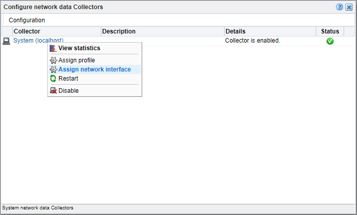
This section can be skipped if your RUEI instance is deployed from OCI Marketplace.Configure RUEI NPA Collector to only use the L2TP tunnel aggregation device, and discard any other tunnel interfaces. Log in to the RUEI web user interface as admin, and perform the following steps:
- Click on the ‘Configuration’ tab
- Click on the ‘Collector Profiles’ in the left pane
- Click on ‘Configure network data Collectors’ in the main pane
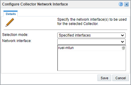
- Right click on ‘System (localhost)’ and click ‘Assign network interface’
- Set ‘Selection mode’ to ‘Specified interfaces’

- Add the ‘ruei-mtun’ interface.

- Click Save.
The RUEI NPA Collector will automatically be restarted after clicking Save. It takes a couple of minutes before the changes are activated.
Don’t add the ‘ruei-mtun-<NUMBER>’ interfaces to the list of interfaces of a collector. The tunnel tooling aggregates all traffic from the ‘ruei-mtun-<NUMBER>’ interfaces to ‘ruei-mtun’.
Virtual Ethernet TAP and L2TP Tunnel on WEBSERVER
Preparation
The L2TP tunnel configuration requires the proper tunnel source and destination endpoint IPs. In addition, the Virtual Ethernet TAP requires the network interface name which will be mirrored and which TCP/IP ports will be mirrored.
All instructions in this chapter must be performed on the WEBSERVER instance, using SSH, unless otherwise instructed.
Source IP (local, web server)
You can determine the L2TP tunnel source IP using the following command:
ip address showSample Output: 10.10.10.11
Destination IP (remote, RUEI)
You can determine the L2TP tunnel destination IP using the following command:
host <dns-name-RUEI>Example Output: 10.10.10.10
Caution: When the RUEI is behind Network Address Translation (NAT), not the locally configured IP (as can be determined with ip address show on the RUEI instance) must be used, but the NAT (outside) address must be used. Using the host (DNS resolve) command, as above, provides the correct IP address in most circumstances.
Web server port number
Please consult the configuration of your web server for the TCP/IP port number the server is running on. Alternatively, use the auto port/service detection tools as discussed in Transmit Diagnostics (Verify Incoming Traffic to Local Services).
Example: port 80
Mirror network interface
Please consult the configuration of your web server and your network setup to determine the name of the ethernet network interface the Virtual Ethernet Network TAP will be mirroring. Alternatively, or to validate, use netstat -tpln, ip link, and tcdump tools to locate on which network interface the clients to web server communication takes place.
For example, ens3
Installation
Copy the ux-tunnel-transmit RPM from the RUEI system to the application web server and install it as root user:
rpm -ivh ux-tunnel-transmit-*.rpmNote:
Copy the ux-tunnel-transmit RPM from the RUEI system to the application web server and install it as root user: The RPM can be found in /root/ruei/rpms.
Setup
Configure Virtual Network TAP and L2TP tunnel
- As root user, create the configuration file:
cd /opt/ruei/tunnel/transmit/conf cp tunnel.conf.example tunnel.conf - Configure the transmit tunnel using tunnel source and destination IPs retrieved above. Add a line to the
tunnel.confusing the following format:receiving-side-ip transmit-side-ip mirror-if-name mirror-port-listExample:
10.10.10.10 10.10.10.11 ens3 i80This configuration instructs the helper tooling to setup a Virutal Network TAP and L2TP tunnel (transmit side) between 10.10.10.11 (WEBSERVER) and 10.10.10.10 (RUEI).
Note:
Notice the ‘i’ in front of the port number (80). This instructs the Virtual Tap to mirror ingress traffic. Alternatively, the ‘o’ prefix can be used to mirror egress traffic. It is possible to mirror multiple ports. Add each port (with its prefix) to a comma separated list (no spaces). In addition, it it possible to mirror all traffic by using the keyword ‘all’ in the mirror port list.
Note:
The transmit side can handle one tunnel.
Start Virtual Network TAP and L2TP tunnel
Start the tunnel service.
Note:
If the tunnel service is currently running, stop it first, and then restart the service.systemctl stop ux-tunnel-transmit
systemctl start ux-tunnel-transmitVerify Virtual Network TAP and L2TP tunnel
List the L2TP tunnel interfaces:
ip linkExample Output:
15: ruei-tun1: <BROADCAST,NOARP,PROMISC,UP,LOWER_UP> mtu 64000 qdisc prio master ruei-br1 state UNKNOWN mode DEFAULT group default qlen 1000 link/ether [MAC] brd ff:ff:ff:ff:ff:ff
16: ruei-br1: <BROADCAST,NOARP,PROMISC,UP,LOWER_UP> mtu 64000 qdisc noqueue state UP mode DEFAULT group default qlen 1000 link/ether [MAC] brd ff:ff:ff:ff:ff:f
17: ruei-veth1in@ruei-veth1out: <BROADCAST,MULTICAST,NOARP,PROMISC,UP,LOWER_UP> mtu 64000 qdisc noqueue state UP mode DEFAULT group default qlen 1000 link/ether [MAC] brd ff:ff:ff:ff:ff:ff
18: ruei-veth1out@ruei-veth1in: <BROADCAST,MULTICAST,NOARP,PROMISC,UP,LOWER_UP> mtu 64000 qdisc noqueue master ruei-br1 state UP mode DEFAULT group default qlen 1000 link/ether [MAC] brd ff:ff:ff:ff:ff:ff
Step 3: Verify traffic is received by the RUEI NPA Collector
Before continuing this chapter, make sure that the port numbers of your application(s) specified in the Virtual Network TAP and Tunnel configuration, are also added as protocol in RUEI. Protocol configuration can be found in the RUEI UI in the section Configuration > Security > Protocols.
To verify traffic is received by the RUEI NPA Collector, follow the steps below in the RUEI web user interface as an admin user:
- Click the Configuration tab.
- Click Security in the left pane.
- Click Protocols in the left pane.
- Click the protocol (HTTP or HTTPS depending on application configuration) in the main pane to open Edit Profile Ports window.
- Enter the port number, and click Add.
- Click Save.
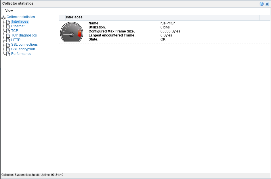
- Click Configure network data Collectors in the main pane.
- Click System (localhost) to open the collector statistics window.

- Click on the various statistics menu items in the left pane to verify traffic reception. The interface on which mirrored ethernet is coming in, is ruei-mtun.
Step 4: Configure an Application Instance/Suite in RUEI
Once traffic is flowing in correctly, it’s time to configure a suite or application instance in RUEI. See Working With Suites and Web Services in the Oracle® Real User Experience Insight User's Guide for more information.
In case traffic is not flowing in as expected, see Diagnostics.
Diagnostics
The Virtual TAP and L2TP best practice contains various virtual network interfaces and the tunnel may need to pass various firewalls. In case the traffic is not received correctly, there are various steps to take, to verify the configuration. There are diagnostics steps for both the transmit and receive side.
Transmit Diagnostics
Verify Incoming Traffic to Local Services
The first step is to verify whether expected web traffic is flowing into the web application server.
Use the following tool, to automatically detect and list traffic (connections) to local services (including web application servers) aggregated by Server IPs and Server Port. By default the tool will look at packets on the tunnel mirror interface (eth0 in this example) previously configured. Supply a different interface to perform the same check on different interfaces.
cd /opt/ruei/tunnel/transmit
./ux-tunnel-transmit diag traffic servers
Example Output:
[info] Detecting server IPs and ports on interface 'eth0', capture time: 30s, max packets: 1000
[info] Using filter: tcp[tcpflags] == tcp-syn|tcp-ack
[info] Server-IP Port Connections
[info] 10.10.10.01 80 38
[info] 10.10.10.02 7001 3
Verify Tunnel Status
Due to various local causes, packets may not be accepted by the L2TP tunnel and are silently dropped. Use the following tool to verify the tunnel status on the transmit side.
./ux-tunnel-transmit diag tunnel checkExample Output:
[info] Interface Local IP Remote IP Tx: packets Tx: errors Tunnel status
[info] ruei-tun1 10.10.10.10 10.10.10.11 0 0 OK
Verify L2TP Traffic Leaving the System
Use the following command to verify L2TP encapsulated packets are leaving the transmit system. Eth0 is used below as the interface over which the L2TP packets are leaving the system. Please replace with the actual interface over which L2TP packets are being routed.
/usr/sbin/tcpdump -n -nn -i eth0 proto l2tpExample Output:
tcpdump: verbose output suppressed, use -v or -vv for full protocol decode
listening on eth0, link-type EN10MB (Ethernet), capture size 65535 bytes
08:03:29.170192 IP 10.10.10.10 > 10.10.10.11: l2tp 106
08:03:29.380252 IP 10.10.10.10 > 10.10.10.11: l2tp 106
08:03:29.590259 IP 10.10.10.10 > 10.10.10.11: l2tp 106
Receive Diagnostics
Verify Incoming Tunnels
Use the following tool to automatically detect any incoming L2TP tunnel. Each tunnel configured and started with ux-tunnel-transmit will transmit a keep alive ping every 20 seconds. This keep alive ping is used to detect incoming tunnels.
sudo ./ux-tunnel-receive diag monitor detectExample Output:
[info ] Detecting tunnels on interface 'any', capture time: 30
[info ] Type Dst-IP Src-IP Tunnel-ID NAT-Status
[info ] L2TP 10.10.10.10 192.168.10.11 10.10.10.11(168430091) yes
[info ] L2TP 10.10.10.10 192.168.10.12 10.10.10.12(168430092) yes
[info ] Detected tunnels: 2
L2TP tunnels require a tunnel ID. By default, the transmit side, uses it’s local tunnel source IP as tunnel ID. In case NAT is applied in the network, the Src-IP on the RUEI receive system may be different. If that’s the case, make sure to configure the tunnel not just by Src-IP and Dst-IP in the tunnels.conf file, but include the tunnel-ID, for example:
16859033
Verify Tunnel Status
Due to various local causes, packets may not be accepted by the L2TP tunnels and are silently dropped. Use the following tool to verify the status of each tunnel on the receive side.
./ux-tunnel-receive diag tunnels checkExample Output:
[info ] Interface Local IP Remote IP Rx: packets Rx: errors Tunnel status
[info ] ruei-mtun-00000 10.10.10.10 10.10.10.11 180144698 0 OK
[info ] ruei-mtun-00001 10.10.10.10 10.10.10.12 0 0 OK
When a tunnel interface reports errors, its tunnel status will be reported as “FAIL”.
Verify Incoming Traffic on the Tunnel Aggregation Interface
All traffic coming in from all tunnels, are aggregated into ‘ruei-mtun’ on the receive side.
Use the following tool, to automatically detect and list traffic (connections) to mirrored services (including web application servers) aggregated by Server IPs and Server Port. By default, the tool will look at packets on the tunnel aggregation interface, ‘ruei-mtun’.
sudo ./ux-tunnel-receive diag traffic serversExample Output:
[info] Detecting server IPs and ports on interface 'ruei-mtun', capture time: 30s, max packets: 1000
[info] Using filter: tcp[tcpflags] == tcp-syn|tcp-ack
[info] Server-IP Port Connections
[info] 10.10.10.01 80 38
[info] 10.10.10.02 7001 3
Verify L2TP Traffic Entering the System
Use the following command to verify L2TP encapsulated packets are entering the receive system. Eth0 is used below as the interface over which the L2TP packets are entering the system. Please replace with the actual interface over which L2TP packets are being received.
./usr/sbin/tcpdump -n -nn -i eth0 proto l2tpExample Output:
tcpdump: verbose output suppressed, use -v or -vv for full protocol decode
listening on eth0, link-type EN10MB (Ethernet), capture size 65535 bytes
08:03:29.170192 IP 10.10.10.11 > 10.10.10.10: l2tp 106
08:03:29.380252 IP 10.10.10.11 > 10.10.10.10: l2tp 106
08:03:29.590259 IP 10.10.10.11 > 10.10.10.10: l2tp 106
Other Diagnostics
Interface Statistics
Use ip -s -d link show to list the available network interfaces, including interface statistics. Verify each of the virtual interfaces involved with the Virtual TAP / L2TP tunnel don’t display errors.
Traffic Control Statistics
Low-level packet filtering and mirroring is done using the Linux Traffic Control(tc) system. Use tc -s filter show to display low-level statistics, including error counters.