5 Maintenance

This chapter explains Acme Packet 3900 hardware maintenance procedures.

Although several user-replaceable components of the Acme Packet 3900 are hot-swappable, some limited Acme Packet 3900 maintenance procedures require that you shut down the system.

Examples of maintenance procedures which require you to shut down the unit include:
  • Removing the unit from the equipment rack for any reason
  • Removing the cover from the chassis
  • Replacing transcoder DSP modules
  • Replacing the T1/E1 TDM card.
General caveats for Acme Packet 3900 maintenance:
  • Always observe correct ESD procedures.
  • Before you start any maintenance procedure which includes parts replacement, make sure you have the correct part on-hand. Any user-replaceable components may be ordered in advance from Oracle.
  • Oracle recommends stocking replacement parts for:
    • Air filters
    • Fans
    • Power supplies
    • Optical transceivers
    • DSP modules

System Shutdown

Before you shut down or restart the Acme Packet 3900, ensure that there are no active calls in progress. The command to show active calls is “show sessions.”

ACMEPACKET# show sessions

Procedures to reroute call and network traffic around the Acme Packet 3900 are outside the scope of this guide.

You can set the Acme Packet 3900 to reject all incoming calls from your system with the set-system-state command. When set to offline, this command lets calls in progress continue uninterrupted, but no new calls are admitted.

After all call processing has stopped, you can power off your Acme Packet 3900. Shutting down the system is appropriate when you are replacing a power supply or are removing the Acme Packet 3900 from the equipment rack.

Rejecting Incoming Calls

To reject all incoming calls on the Acme Packet 3900:
  1. In Superuser mode, type show sessions to see all the current calls.
    ACMEPACKET# show sessions
  2. Type set-system-state offline and press Enter.
    ACMEPACKET# set-system-state offline
     Setting system state to going-offline, process will complete when all current calls have completed
     ACMEPACKET#

Shut Down the Acme Packet

  1. In Superuser mode, type halt.
  2. To confirm the halt request, type Y.
  3. When the console indicates shutdown is completed, unplug the AC power cords from the power supplies on the rear panel.
  4. Confirm that all fans are off.

Rebooting, Resetting, and Power Cycling

Reboot

Rebooting the Acme Packet 3900 shuts down the system in an orderly fashion and then automatically restarts it. The operating system gracefully shuts down as processes are terminated and the file system is stopped. While the system and its processes are stopped, all call processing is immediately halted. You may therefore wish to perform tasks that call for a reboot during off-peak maintenance hours.

Rebooting the Acme Packet 3900 is required every time you upgrade with a new version of the software.

Save your configurations before rebooting. Refer to the Maintenance and Troubleshooting Guide for a full explanation of this procedure. The save-config command is used to save the configuration in the example below.

To reboot:
  1. Type save-config to save any configuration changes you made.
    ACMEPACKET# save-config
     Save-Config received, processing.
     waiting 1200 for request to finish
     Request to 'SAVE-CONFIG' has Finished,
     Save complete
     Currently active and saved configurations do not match!
     To sync & activate, run 'activate-config' or 'reboot activate'.
     ACMEPACKET#
  2. Type reboot.
    ACMEPACKET# reboot
           
    -----------------------------------------
    WARNING: you are about to reboot this SD!
  3. Type Y at the confirmation prompt to proceed with the reboot.
    Reboot this SD [y/n]?: y

System Reset

Resetting the Acme Packet 3900 via the reset pushbutton on the rear of the chassis performs a cold reboot. This action is the equivalent of disconnecting the power from the system and then reconnecting it. There is no orderly termination of tasks, and the system shuts down abruptly. You should only reset the Acme Packet 3900 when it becomes unstable and no other means of gaining administrative control is possible.

During a system reset, certain files are not closed properly, and they may become corrupted. If an unclean shutdown is detected, filesystem recovery/repair will be run to ensure the system returns to a stable state. Filesystem verification also runs every 30 boots as a precautionary measure.

Note:

Always try to reboot first from the ACLI before performing a cold reset. Only reset the system as a last resort.
  1. Insert a rigid paperclip-sized tool into the small hole on the rear of the chassis. The system immediately resets and begins its initialization and boot sequence.

Power Cycling

Power cycling the Acme Packet 3900 is the process of turning the chassis off and then on again. When power cycling, it is imperative that you wait at least 10 seconds between power down and power up to ensure that all components are completely powered down before restarting the system.

Standby State for HA Nodes

When performing hardware maintenance on the Acme Packet 3900, it is best to minimize any risk of interrupting network traffic or losing data. If the Acme Packet 3900s are configured as an HA node, you should only work on the node that is in standby state.

There are two ways to determine the HA state of each Acme Packet 3900 in an HA pair.
  1. If you are in the same physical location as the Acme Packet 3900 you can view the HA LEDS on the front bottom right. A standby unit lights the STBY LED, while an active unit lights the ACT LED.
  2. If you are not in the same physical location as the Acme Packet 39004, you can use the ACLI show health command. The output of this command indicates the current HA state of the Acme Packet 3900.

Once you have determined that the Acme Packet 3900 due for maintenance is in standby state, you can continue with the appropriate procedures to replace a part.

If you need to perform maintenance on the active Acme Packet 3900 you need to manually force the two Acme Packet 3900s to switch HA states. Forcing a switchover renders the currently active Acme Packet 3900 in Standby state, and the current standby Acme Packet 3900 will assume all traffic processing and forwarding as the active system.

Note:

This procedure is only applicable to an HA deployment.
To force a Acme Packet 3900 into the standby HA state:
  1. Use the show health command to verify the State attribute has the value "Active".
    SBC1# show health
        Media Synchronized            true
        SIP Synchronized              true
        MGCP Synchronized             true
        H248 Synchronized             disabled
        Config Synchronized           true
        Collect Synchronized          disabled
        Radius CDR Synchronized       disabled
        Rotated CDRs Synchronized     disabled
        Active Peer Address           0.0.0.0
    
    Redundancy Protocol Process (v3):
        State                           Active
        Health                          100
        Lowest Local Address            169.254.1.1:9090
        1 peer(s) on 2 socket(s):       SML-STIC-39002: v3, Standby, health=100, max silence=1050
                                        last received from 169.254.1.2 on wancom1:0
        Switchover log:        
        Jun 25 19:03:02.029: Active to Becoming Standby
        Jun 25 19:04:54.684: Standby to Becoming Active
    
    SBC2# show health        
        Media Synchronized            true
        SIP Synchronized              true
        MGCP Synchronized             true
        H248 Synchronized             disabled 
        Config Synchronized           true
        Collect Synchronized          disabled
        Radius CDR Synchronized       disabled 
        Rotated CDRs Synchronized     disabled
        Active Peer Address           169.254.2.1
    Redundancy Protocol Process (v3):
        State                           Standby
        Health                          100
        Lowest Local Address            169.254.1.2:9090
        1 peer(s) on 2 socket(s):       SML-STIC-39001: v3, Active, health=100, max silence=1050
                                        last received from 169.254.2.1 on wancom2:0
  2. Use the display-current-cfg-version command to verify the configuration version is the same on both the active and standby nodes.
    SBC1# display-current-cfg-version
     Current configuration version is 5
    
     SBC2# display-current-cfg-version
     Current configuration version is 5
     NETNETSBC2#

    Note:

    While the two current configuration version numbers on the two systems do not need to match each other, they MUST match the shared running configuration version.
  3. Use the display-current-cfg-version command to verify the running configuration version is the same on both the active and standby nodes.
    SBC1# display-running-cfg-version
    Running configuration version is 5
    
    SBC2# display-running-cfg-version
    Running configuration version is 5
    NETNETSBC2#

    Note:

    While the two running configuration version numbers on the two systems do not need to match each other, they MUST match the shared current configuration version.
  4. Use the notify berpd force command to initiate a switchover from the active to the standby node.
    SBC1# notify berpd force
  5. Wait for the other Acme Packet 3900 to transition to the standby state. Confirm that it is in the standby state with the show health command.
    SBC2# show health
Refer to the Upgrade section of the Maintenance and Troubleshooting Guide for more information.

Maintenance With Power

Some maintenance tasks may be performed without powering down the system.

  • Clean air inlets in the front left bezel
  • Replace air filters
  • Clean fan modules
  • Replace fans
  • Replace power supplies
  • Replace optical transceivers

Maintaining the Cooling Components

The Acme Packet 3900 air filter removes airborne particles before they are drawn into the Acme Packet 3900 chassis. To prevent system malfunction and prolong the life of the system’s cooling components, do these things:
  • Replace the fan filter every three months
  • Clean the air inlets once a week.

Cooling maintenance encompasses cleaning the fan module and cleaning the air inlets on the front of the Acme Packet 3900 chassis. Cleaning the fan module requires that you remove the module itself. If you are not shutting down the Acme Packet 3900, this procedure must be performed quickly or else the system may overheat and cause packet processing to stop.

This maintenance should be performed alongside other preventive maintenance to take place within a planned maintenance or downtime window, during off-peak hours.

Fan and Air Filter Maintenance

This section explains how to remove a fan and replace the air filter on your Acme Packet 3900.

Note:

You can perform routine maintenance on the Acme Packet 3900 front panel fans and air filter with the unit normally installed in the equipment rack. Also, you do not need to remove the the power from the chassis.
Clean the Air Inlets

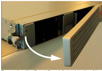
  1. Remove the bezel from the chassis by gripping the two left corners and pulling on it. The bezel is held on magnetically.
    Removing bezel
  2. Remove the air filter.
    Removing air filter
  3. Clean the bezel by gently wiping it with a clean, dry cloth or by blowing compressed air through it.
  4. Install a clean air filter on the bezel.
  5. Attach the bezel to the unit by hooking the bezel's right side into its slots and pivoting until the magnet catches the chassis.
Replace a Fan
To maintain unit operations, you must be able to remove the malfunctioning fan and quickly replace it with a functioning one to prevent the unit from overheating. To obtain a replacement fan, contact Oracle customer support.
  1. Remove the bezel.
  2. Unscrew the captive screws at the upper left and lower right corners of the fan you are replacing.
  3. Pull the fan out of the chassis.
    Move the fan to an ESD-safe location.
  4. Carefully align the pins on the back of the new fan with the holes in the chassis midplane and insert the fan into the slot.

    Note:

    The PCB power connector must be on the lower left side of the fan module when inserted into the chassis.
  5. Tighten the two captive screws.
  6. Re-attach the bezel.

Power Supply Removal and Replacement

You can replace malfunctioning power supplies yourself.

Note:

Ground yourself first using appropriate ESD grounding equipment such as a wrist strap.
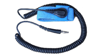
Image showing a ESD Grounding Strap

Note:

Power supplies can be removed from the chassis while it is still installed in the rack and while the second power supply is providing system power; this is called a warm swap.

Note:

After unplugging a power supply, disconnect it from the power source before you remove or install it in the chassis.
To remove a power supply from the chassis:
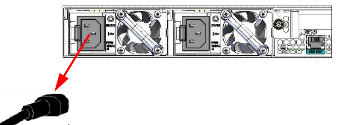
  1. Remove the power cables from the power supplies.
    Diagram showing Removing the Power Cords
  2. With your thumb, push the black locking tab on the right to unlock the power supply from the chassis.
    Diagram showing Releasing the Locking Tab
  3. Holding the handle, pull the power supply until it is completely out of the chassis.
  4. Move the power supply to an ESD-safe location.
Installing a Power Supply
To install a power supply in the Acme Packet 3900 chassis:
  1. Insert the power supply into the empty power supply slot located on the rear panel of the chassis.

    The labels on the power supply face upward.

    DANGER:

    NEVER power up a power supply before it is installed in the chassis.
  2. Push the power supply handle until the power supply is engaged with the mid plane.
  3. Connect the power cord to the power supply.

Optical Transceiver Removal and Replacement

Your troubleshooting and diagnostics might reveal that the optical transceiver component of an optical physical interface card needs to be replaced. The optical transceiver serves two functions:
  • Converts electrical signals into optical signals used to communicate with other optical networking equipment.
  • Serves as the receptacle for the LC duplex fiber optic connectors.

Optical transceivers are hot swappable and may be replaced while the Acme Packet 3900 is powered on.

To obtain a replacement optical transceiver, contact customer support.

Note:

To prevent damage to the optical lens, Acme Packet recommends that the protective dust cover stay on the optical transceiver port when the physical interface card is not cabled.
Removing an Optical Transceiver
To remove the transceiver from an NIU transceiver port:
  1. Unplug all fiber optic cables from the optical transceiver to be replaced. Image showing NIU Transceiver Ports
  2. Pull the bale clasp latch out and down. It will pivot downwards on its hinge. Image showing Lowering the Bale Clasp Latch
  3. Holding the extended bale clasp latch, pull the optical transceiver fully out of its socket of the physical interface card. Image showing Removing the Optical Transceiver
Install an Optical Transceiver
To install an optical transceiver:
  1. Slide the replacement optical transceiver into the socket on the rear panel.Image showing Inserting the Optical Transceiver into the Socket
  2. Press on the face of the optical transceiver to seat it in the socket.Image showing Seating the Optical Transceiver
  3. Flip the bale clasp latch back into the rest position. Image showing Closing the Clasp Latch
  4. Reconnect the optical cables to their corresponding ports. Image showing Reconnecting Optical Cables
Copper Transceivers

Copper transceivers are also available for the Acme Packet 3900 System. They are removed and replaced similarly to the optical transceivers.

Maintenance Without Power

Some maintenance tasks must be performed after powering down the system.

  • Remove the chassis cover
  • Remove the chassis from an equipment rack
  • Remove and replace transcoder DSP modules
  • Remove and replace T1/E1 TDM modules

Remove the Chassis Cover

Caution:

Always gracefully power down the Acme Packet 3900 and then disconnect the power supplies from the power source when removing the chassis cover.
  1. Ensure there is enough slack in the unit cabling to allow the chassis to slide forward.
  2. Remove the power from the Acme Packet 3900.
  3. Loosen the two thumbscrews on the rear panel.
  4. Loosen the two thumbscrews on the front panel.
  5. Pull the Acme Packet 3900 to the front of the rack until the chassis assembly stops.
  6. Push the chassis cover backwards about ½ inch.
  7. Lift the cover up until it is free of the chassis.

Removing the Unit from an Equipment Rack

  1. Power down the unit gracefully using the ACLI commands.
  2. Depress the power pushbutton.
  3. Remove the two power cords from the power supplies in the rear of the system.
  4. Remove and label all attached network cables and console cable from their respective ports on the chassis.
  5. Loosen the thumbscrews that secure the Acme Packet 3900 to the equipment rack slide rails.
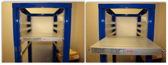
  6. Slide the unit forward.
    removing unit

    When mounted in slide rails, the chassis will stop when the locking clip pin on the chassis slide rail engages with the equipment rack slide rail.

  7. Push the locking clip latches on both sides of the chassis inwards to unlock the slide rails from each other.
    locking latch
  8. Pull the the Acme Packet 3900 chassis completely from the slide rails.
  9. Pull the unit with the slide rails still attached out of the equipment rack, and move it to an ESD-safe location.

    Note:

    One person should support the Acme Packet 3900 from below while the other person removes the chassis from the equipment rack.

Replacing Transcoder DSP Modules

Up to 5 transcoder DSP modules may be installed on the Acme Packet 3900 printed circuit board (PCB).
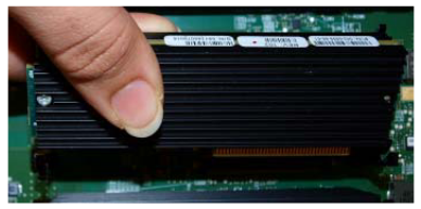
Image showing transcoding DSP modules

There are slots for installing the transcoder DSP modules in one location on the Acme Packet 3900 PCB. The slots are numbered 0-4. Slot 0 is the closest slot to the edge of the unit when looking at it from the front of the chassis. Transcoder DSP modules should be installed consecutively in numerical order, starting with slot 0.
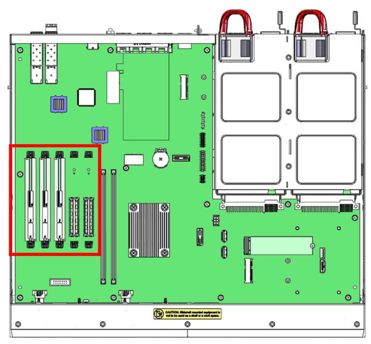
3900 board
Guidelines
Please read and follow these guidelines prior to installing or removing the transcoder DSP module:
  • The transcoder DSP module can be installed only in the designated location.
  • Ground yourself and follow proper ESD grounding procedures.
  • Remove the transcoder DSP module from the shipped packaging.
  • The installation of these modules should be performed during low-traffic periods or during times of scheduled maintenance.
  • Follow industry-standard procedures to ensure ESD protection.
  • When installing or removing a DSP module, move the card to an ESD-safe location.

Note:

Before handling any components, follow the proper ESD grounding procedures. Failure to do so could damage the card and its components.

Required Parts

The following parts are required to replace the transcoder DSP module.
  • ESD wrist strap
  • ESD-safe location
  • Transcoder DSP module
Removing the Transcoder DSP Module
The following procedure describes how to remove the transcoder DSP module.
Prerequisites:
  • Provide an ESD-safe location to place the transcoder DSP module.
  • Wear an ESD wrist strap.
  • On the Acme Packet 3900 or Acme Packet 3950/4900, remove the chassis cover.
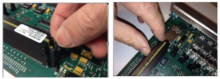
  1. Use a fingertip to release the catch holding either end of the transcoder DSP module.
    Image showing Releasing the Fastener Holding the Transcoder DSP Module
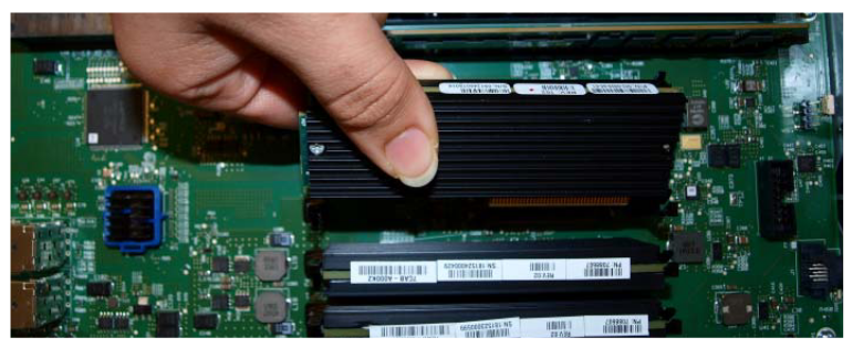
  2. Once the fasteners are detached from both sides of the transcoder DSP module, hold the center of the module between your finger and thumb and slowly remove the module.

    Be careful to keep the module level while removing it and guide it smoothly through the guide slots on either side.

    Image Showing Removing the Transcoder DSP Module
  3. Place the transcoder DSP module on an ESD-safe antistatic surface.
Installing the Transcoder DSP Module
The following procedure describes how to install the transcoder DSP module onto the PCB.
Prerequisites:
  • Place the new transcoder DSP module in an ESD-safe location.
  • Wear an ESD wrist strap.
  1. Grasp the transcoder DSP module between your thumb and index finger and line up both sides of the module with the slot guides attached to the PCB.
    Image showing Installing the Transcoder DSP Module
  2. Using your thumb on your other hand, guide the module evenly into the slot guides located on each side as you lower the component into the connector. Press evenly across the top of the connector to fully seat the transcoder DSP module on the PCB.

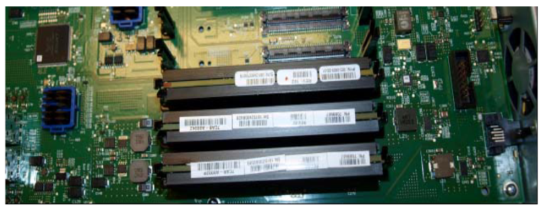
    The module is fastened to the connector at one end while at the other end, the board rests on two standoffs attached to the PCB.

    Image showing Installed Transcoding DSP Module

Removing and Replacing the T1/E1 TDM Module

The TDM module is located near the rear of the board.
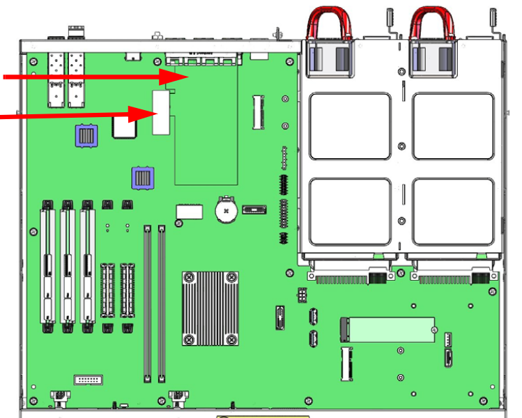
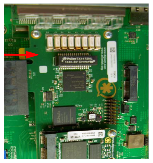
Location of TDM module

TDM module

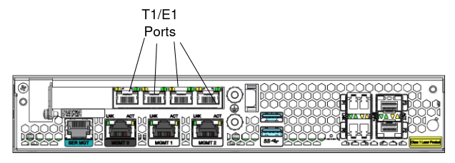
Location of T1/E1 ports

Guidelines
Read and follow these guidelines prior to installing or removing the TDM module:
  • Ground yourself and follow proper ESD grounding procedures.
  • Remove the transcoder TDM module from the shipped packaging.

Note:

In the box with the new T1/E1 TDM modules, there will be aTelecom label in a plastic envelope. Attach the Telecom label to the chassis cover as described below.

Note:

The installation of these modules should be performed during low-traffic periods or during times of scheduled maintenance.

Caution:

Before handling any components, follow the proper ESD grounding procedures. Failure to do so could damage the card and its components.

Required Parts

The following parts are required to replace the transcoder DSP module.
  • ESD wrist strap
  • ESD-safe location
  • New or replacement TDM module
  • Telecom label to attach to the chassis cover
Remove the TDM Module
  1. Remove the Acme Packet 3900 cover.

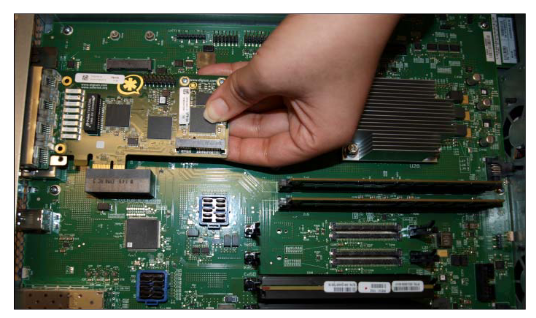
    The T1/E1 TDM module is installed into the rear panel of the chassis and attached through a PCI Express x4 connector. The module is raised about a quarter of an inch off of the chassis PCB.

    Internal view of TDM module

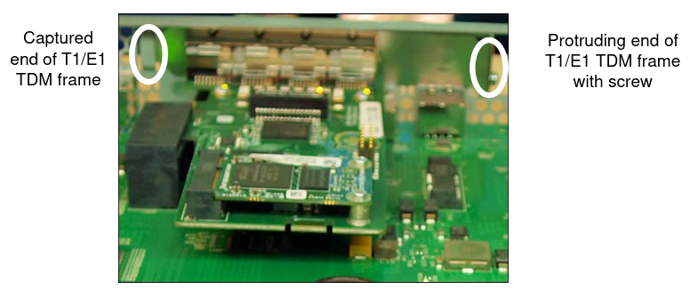
    Part of the module is a piece of metal connected at 90 degrees to the module PCB. This piece contains the four T1/E1 ports visible when looking at the rear panel of the chassis. The metal extends on either side of the port area. When looking from the inside of the chassis, the part of the metal to the left of the ports continues straight and is attached to the inside of the rear panel. To the right of the ports, the metal bends 90 degrees towards the rear of the chassis, and is inserted through the rear panel.

  2. Remove the screw on the outside of the chassis that holds the module seated against the rear panel of the chassis.
  3. Grasp the module by its edges. Pull the right side of the module out of the rear panel slot, and, at the same time, slide the left side of the piece of metal from the rear panel.
    Disconnect the TDM module
  4. Pull the module laterally out of the plug and away from the rear panel of the chassis. You may have to work the module back and forth as you pull, in order to disengage the module from the two directions.
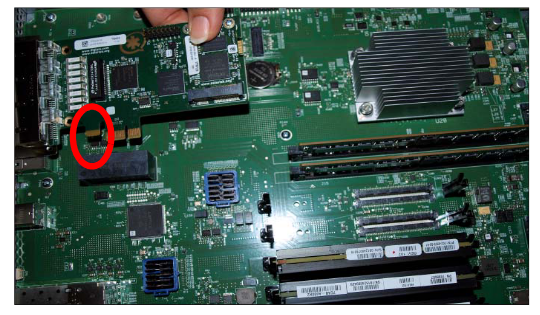
    Internal view showing key

    Note that there is a gap in the edge connector of the module PCB. There are metal bands on either side of the gap. The left-most part of the connector section is outside of the plug.

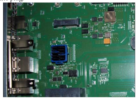
    TDM module removed
  5. When the module is fully disengaged, remove it from the chassis area to an ESD-safe location.
Install the TDM Module
  1. Grasp the module by its edges. Orient it towards the plug and the rear panel of the chassis as you found the original module.
  2. Push the right side of the module into the chassis rear panel slot, and, at the same time, slide the left side of the piece of metal into the rear panel.
  3. Push the module laterally into the plug and toward the rear panel of the chassis. You may have to work the module back and forth as you pull, in order to secure the module from the two directions.

    Note that there is a gap in the edge connector of the module PCB. There are metal bands on either side of the gap. The left-most part of the connector section is outside of the plug.

  4. Attach the screw that secures the piece of metal attached to the module to the rear panel.
  5. After you finish installing the module, replace the cover of the unit.
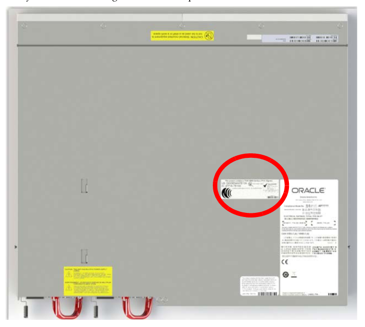
  6. If this is not a replacement T1/E1 card, affix the Telecom label to the top cover.
    Regulatory label